EP0278675A2 - Ball valve - Google Patents
Ball valve Download PDFInfo
- Publication number
- EP0278675A2 EP0278675A2 EP88300930A EP88300930A EP0278675A2 EP 0278675 A2 EP0278675 A2 EP 0278675A2 EP 88300930 A EP88300930 A EP 88300930A EP 88300930 A EP88300930 A EP 88300930A EP 0278675 A2 EP0278675 A2 EP 0278675A2
- Authority
- EP
- European Patent Office
- Prior art keywords
- valve
- stem
- ball
- valve chamber
- body component
- Prior art date
- Legal status (The legal status is an assumption and is not a legal conclusion. Google has not performed a legal analysis and makes no representation as to the accuracy of the status listed.)
- Withdrawn
Links
Images

Classifications
-
- F—MECHANICAL ENGINEERING; LIGHTING; HEATING; WEAPONS; BLASTING
- F16—ENGINEERING ELEMENTS AND UNITS; GENERAL MEASURES FOR PRODUCING AND MAINTAINING EFFECTIVE FUNCTIONING OF MACHINES OR INSTALLATIONS; THERMAL INSULATION IN GENERAL
- F16K—VALVES; TAPS; COCKS; ACTUATING-FLOATS; DEVICES FOR VENTING OR AERATING
- F16K5/00—Plug valves; Taps or cocks comprising only cut-off apparatus having at least one of the sealing faces shaped as a more or less complete surface of a solid of revolution, the opening and closing movement being predominantly rotary
- F16K5/06—Plug valves; Taps or cocks comprising only cut-off apparatus having at least one of the sealing faces shaped as a more or less complete surface of a solid of revolution, the opening and closing movement being predominantly rotary with plugs having spherical surfaces; Packings therefor
- F16K5/0626—Easy mounting or dismounting means
- F16K5/0642—Easy mounting or dismounting means the spherical plug being insertable from one and only one side of the housing
-
- F—MECHANICAL ENGINEERING; LIGHTING; HEATING; WEAPONS; BLASTING
- F16—ENGINEERING ELEMENTS AND UNITS; GENERAL MEASURES FOR PRODUCING AND MAINTAINING EFFECTIVE FUNCTIONING OF MACHINES OR INSTALLATIONS; THERMAL INSULATION IN GENERAL
- F16K—VALVES; TAPS; COCKS; ACTUATING-FLOATS; DEVICES FOR VENTING OR AERATING
- F16K27/00—Construction of housing; Use of materials therefor
- F16K27/06—Construction of housing; Use of materials therefor of taps or cocks
- F16K27/067—Construction of housing; Use of materials therefor of taps or cocks with spherical plugs
-
- F—MECHANICAL ENGINEERING; LIGHTING; HEATING; WEAPONS; BLASTING
- F16—ENGINEERING ELEMENTS AND UNITS; GENERAL MEASURES FOR PRODUCING AND MAINTAINING EFFECTIVE FUNCTIONING OF MACHINES OR INSTALLATIONS; THERMAL INSULATION IN GENERAL
- F16K—VALVES; TAPS; COCKS; ACTUATING-FLOATS; DEVICES FOR VENTING OR AERATING
- F16K5/00—Plug valves; Taps or cocks comprising only cut-off apparatus having at least one of the sealing faces shaped as a more or less complete surface of a solid of revolution, the opening and closing movement being predominantly rotary
- F16K5/06—Plug valves; Taps or cocks comprising only cut-off apparatus having at least one of the sealing faces shaped as a more or less complete surface of a solid of revolution, the opening and closing movement being predominantly rotary with plugs having spherical surfaces; Packings therefor
- F16K5/0663—Packings
- F16K5/0673—Composite packings
- F16K5/0678—Composite packings in which only one of the components of the composite packing is contacting the plug
-
- F—MECHANICAL ENGINEERING; LIGHTING; HEATING; WEAPONS; BLASTING
- F16—ENGINEERING ELEMENTS AND UNITS; GENERAL MEASURES FOR PRODUCING AND MAINTAINING EFFECTIVE FUNCTIONING OF MACHINES OR INSTALLATIONS; THERMAL INSULATION IN GENERAL
- F16K—VALVES; TAPS; COCKS; ACTUATING-FLOATS; DEVICES FOR VENTING OR AERATING
- F16K5/00—Plug valves; Taps or cocks comprising only cut-off apparatus having at least one of the sealing faces shaped as a more or less complete surface of a solid of revolution, the opening and closing movement being predominantly rotary
- F16K5/08—Details
- F16K5/14—Special arrangements for separating the sealing faces or for pressing them together
- F16K5/20—Special arrangements for separating the sealing faces or for pressing them together for plugs with spherical surfaces
- F16K5/205—Sealing effected by the flowing medium
Definitions
- the invention relates to ball valves.
- the invention is especially suited for small, compact multi-service ball valves; however, the invention could be applied to valves of many sizes or in special service valves.
- the manufacture of ball valve bodies or housings often requires a significant amount of relatively complex machining whether the bodies are formed from bar stock, forged or cast.
- the housings have often been designed as multi-part assemblies having separate bonnet components and scerw-threadedly attached end pieces.
- the valves have often been provided with separate inserts or sleeve-like members for carrying the ball seal and body seal elements. Consequently, the resulting valves have often been relatively complex and/or a compromise in design.
- An object of the present invention is to provide an extremely rugged design of ball valve which is especially suited for use in small size ball valves.
- the design is relatively simple and offers advantages for valves used in high pressure service since both the ball and the operating stem are blow-out proof.
- a primary object of the invention is the provision of a ball valve which is especially adapted for manufacture in small sizes.
- Another object is the provision of a ball valve design in which the ball and stem are blow-out proof.
- a further object of the invention is the provision of a ball valve of the type in which the bearing surfaces of the stem or operating assembly are isolated from the valve chamber so that the bearing surfaces are non-wetted surfaces.
- Yet another object is the provision of a ball valve which is capable of bi-directional use and has a floating ball and seat ring arrangement.
- the invention comprises a ball valve including a first unitary body component having first and second axially disposed ends with a cylindrical valve chamber extending inwardly from the first end and terminating in a transversely extending end face.
- a first flow passage extends into the first body component from the second end to open into the valve chamber axially of the end face.
- Formed about the first flow passage is a first sleeve section extending axially into the valve chamber.
- a cylindrical stem-receiving opening is also formed in the first body component and extends radially outwardly from the valve chamber to open to the exterior of the first body component through an inwardly facing shoulder.
- a second unitary body component is releasably connected to the first end of the first body component to close the valve chamber and defines a second flow passage opening into the valve chamber in axial alignment with the first flow passage.
- Inner and outer radially spaced sleeve sections are formed intergrally with the second body component and extend into the valve chamber circumferentially about the second flow passage.
- the inner sleeve section is aligned with the first sleeve section on the first body component.
- Mounted in the valve chamber is a valve ball axially aligned with the first and second flow passages.
- Seat rings are positioned about the first and inner sleeve sections and are biassed into engagement with the valve ball.
- An operating stem is provided for rotating the ball.
- the operating stem is positioned axially of the stem-receiving opening and has an outwardly extending integral flange and a stem shoulder located axially inwardly of the body shoulder.
- Stem seal means are located between the flange and the stem shoulder and a resilient bearing ring is located between the body shoulder and the flange.
- stem-receiving opening with an integral flange having the stem shoulder thereon and the relationship of the stem flange, stem shoulder and stem bearing are such that the stem is blow-out proof.
- stem bearing surfaces are sealed from the interior of the valve chamber so that the bearing surfaces are non-wetted.
- the valve chamber has an enlarged counterbore formed at the first end thereof.
- the counterbore is sized to receive the outer sleeve section of the second body component and to define an annular space between the outer sleeve section and the first body component.
- the inner diameter of the outer sleeve section substantially corresponds to the diameter of the valve chamber to provide a continuation of the valve chamber and define an annular seat ring-receiving recess which is aligned with a corresponding annular seat ring-receiving recess around the first sleeve section.
- each ring seat ring assembly comprises a resilient O-ring closely surrounding the associated sleeve section and engaging an associated end wall of the valve chamber.
- a seat ring is closely but slidably received in each annular recess and has a first end engaged with the associated O-ring and a second end extending out of the associated recess for sealing engagement with the ball.
- the first end of each seat ring preferably includes integrally formed inner and outer continuous walls or lips which extend axially into the associated recess on radially opposite sides of the associated O-ring.
- the O-rings are sized to be received within the continuous walls or lips and to maintain their associated seat ring compressively engaged with the ball throughout a portion of the range of axial movement of the ball.
- the O-rings are sized relative to the associated recess and the seat ring to limit axial movement of the ball towards the sleeve sections to prevent the ball from engaging the sleeve sections under even extremely high pressure conditions.
- the continuous lips confine the O-ring and prevent O-ring extrusion under high pressure conditions.
- the O-rings act to maintain sufficient preload on the seat rings to seal with the ball under low-line pressure.
- line pressure increases, the ball moves towards the downstream seat, causing increased sealing pressure between the ball and the downstream seat ring.
- the downstream seat ring does, however, have some freedom to move against its respective biassing O-ring, at least until the maximum compression of the O-ring is achieved as controlled by the space available in the annular seat ring-receiving recess.
- a ball valve 10 comprises a housing or body 12 formed of a pair of co-operating first and second body components 14 and 16. As shown in Fig. 4, the body or housing 12 defines a cylindrical, internal valve chamber 18 which carries a rotatably mounted valve element or ball member 20 and co-operating seat or seal assemblies 22 and 24. The ball member 20 is arranged to be rotated between open and closed positions by a handle 26 suitably connected to the ball 20 through a stem assembly 28.
- the first body component 14 includes a generally rectangular first end portion 30 which has a pair of outwardly extending flange sections 32 and 34 formed integrally therewith.
- a hexagonal-shaped second end portion 36 is axially aligned with the first end portion 30.
- a generally cylindrical opening 40 extends axially inwardly from the first end of body component 14 and partly defines the valve chamber 18.
- the opening 40 terminates in a generally transversely extending end wall 42 which defines a first end of valve chamber 18.
- An enlarged counterbore 44 is formed about the inlet end of the opening 40 for reasons to be described.
- a cylindrical flow passage 48 which connects with and is axially aligned with the valve chamber 18.
- the passage 48 has a reduced diameter inner end portion 50 and a larger diameter outer end portion 52.
- Means are provided to permit the passage 48 to be connected to fluid flow lines and the like. Many different types of conventional connecting means could be used. As shown, however, the large diameter portion of the flow passage 48 is provided with female pipe threads for this purpose.
- a sleeve section 54 Closely surrounding the inner end 50 of passage 48 is a sleeve section 54 which extends axially into the valve chamber 18.
- the sleeve section 54 in combination with the outer wall of opening 40 defines an axially open annular recess 56 (Fig. 5).
- bonnet portion 58 Formed integrally with the rectangular end portion 30 of body component 14 is a generally cylindrical bonnet portion 58. As illustrated, the bonnet portion 58 is provided with external threads 62 to permit the valve to be panel-mounted, if desired.
- a stem-receiving opening 60 Formed axially through the bonnet portion 58 transversely to the valve chamber 18 is a stem-receiving opening 60.
- the opening 60 leads to the exterior of the body through a shoulder 65 on a radially inwardly extending circular flange portion 64.
- Body component 16 has a generally hexagonal configuration with a pair of laterally extending flange sections 78 and 80.
- the flange sections 78 and 80 are generally of corresponding shape to the previously mentioned flange sections 32,34 of body component 14.
- the flange sections are provided with aligned openings to allow the body components 14 and 16 to be suitably and releasably interconnected, such as through the use of socket head capscrews 82 and nuts 84 as shown.
- the flange sections 32 and 34 are provided with recesses sized so as to engage the associated nuts 84 to prevent them rotating during tightening of the capscrews 82.
- Recesses provided on flanges 78 and 80 to receive the heads of the socket head capscrews 82 are similar.
- the inner end of body component 16 is arranged to engage with the first end of body component 14 and close the outer end of the valve chamber 18.
- the body component 16 has an axially extending flow passage 86.
- the flow passage 86 has a large diameter section 88 and an inner, smaller diameter section 90 which opens axially to the valve chamber 18.
- the outer end of passageway 86 is provided with female pipe threads for permitting connection of the valve to associated flow lines.
- the inner end wall 91 of the body component 16 is provided with radially spaced and circumferentially continuous second and third sleeve sections 92 and 94 (Fig. 5).
- the second or inner sleeve section 92 is positioned closely about the opening 90 and extends axially of the valve chamber 18 towards the sleeve section 54.
- the third or outer sleeve section 94 is located radially outwardly of the second sleeve section 92 and, in combination therewith, defines an axially open annular recess or groove 96 which is aligned with and generally of the same size as the annular recess 56.
- the inner wall 98 of the outer sleeve section 94 is preferably located at a diameter corresponding to the diameter of opening 40 which defines the valve chamber 18.
- the outer wall 100 of the sleeve section 94 is spaced radially inwardly of the counterbore 44 of opening 40 to define a circumferentially continuous chamber 102.
- the mating body components 14 and 16 are sealed by a resilient O-ring 104 in the chamber 102. Blow-out of the O-ring 104 is prevented by a back-up ring 106 located in the chamber 102 in engagement with the end face of body component 16.
- ball 20 has a central passage 100 which, as is conventional, can be rotated into alignment with the flow passages 48,86 as shown in Fig. 4 or, rotated 90° to a closed position as shown in Fig. 5.
- the ball 20 is mounted axially within the valve chamber 18 between opposed seal ring members 112 and 114.
- the seal rings 112 and 114 are shown as being of identical configuration so that only seal ring 112 will be described in detail and the description thereof is equally applicable to seal ring 114. As shown in Fig.
- seal ring 112 comprises a solid annular body formed from a suitable resilient material, such as polyethylene, PTFE, or the like depending upon the pressures and/or other environmental conditions to which the seal ring is to be subjected.
- the ring 112 is sized so as to be closely but slidably received in the recess 56.
- the seal face 116 of the ring 112 is contoured to closely engage the ball 20 and has a radius on the seal face 116 substantially equal to the radius of the ball.
- each seat ring 112,114 is provided with radially inner and outer circumferentially continuous short walls or lips 113 (Fig. 6).
- the lips 113 are integral with the body of the respective seat ring and extend axially therefrom.
- An O-ring 120 or 122 is received between the associated lips 113.
- the lips 113 are shorter than the normal or uncompressed thickness of the associated O-ring 120 or 122 and closely engage the walls of the associated recess on radially opposite sides of the O-ring.
- the function of lips 113 will subsequently be expalined in more detail but their primary purpose is to radially confine the O-ring 120 and prevent extrusion of the O-ring under high pressure conditions.
- the seal ring 112 and the opposed seal ring 114 are both maintained under a bias towards the ball by the O-rings 120 and 122 being compressed, respectively, between the end faces of the annular recesses 56 and 96 and the associated seal ring.
- the overall length, in an axial direction, of the seal rings and the associated O-rings 120,122 are related to the valve chamber and the ball 20 such that, in the position shown in Fig. 5 the rings sealingly engage the ball with a predetermined contact force sufficient to ensure sealing under low pressure conditions.
- Fig. 6 shows the ball and the seal ring relationships under conditions of high pressure.
- the ball 20 is mounted so that it can move axially of the valve chamber in response to high upstream pressure conditions.
- the ball 20 is moved towards seal ring 114 thereby increasing the seal pressure between the seal face of ring 114 and the ball.
- the ring moves into recess 96, compressing O-ring 122.
- the O-ring is confined radially by the lips 113.
- the compression of the O-ring 122 applies radial forces to the lips 113, causing them to engage the walls of the recess 96 more tightly. This relationship prevents extrusion of the O-ring 122 about the seat ring 114.
- the upstream seat ring 112 moves with the ball 20 for a short distance.
- the seal between seal ring 112 and the ball is broken and the valve chamber area surrounding the ball is subjected to the increased pressure.
- the O-rings 120 and 122 are related to the available space in their respective recesses 56 and 96 such that the maximum movement permitted by the associated seat ring does not enable contact to take place between the ball and the inner sleeve sections 54 and 92.
- seal rings 112 and 114 are substantially fully confined, and enclosed about both their inner and outer surfaces when they are in their maximum loaded conditions.
- the forces acting on the seats are thus substantially pure compression loads which the materials from which such seats are formed can withstand better than bending or tension.
- the seals, the O-rings, and the ball seat cavities are identical to one another and the valve is therefor bi-directional. That is, it can be used with either of the flow passages 48 or 86 serving as the upstream or inlet passage.
- flow passage 86 is the inlet passage
- the ball 20 moves towards seat ring 112 under high pressure conditions in the same manner as previously discussed with respect to seat ring 114 when passage 48 is serving as the inlet.
- stem assembly 28 is arranged to be blow-out proof in that the stem and related elements are totally confined within the valve body by the previously mentioned flange 64. Additionally, the assembly provides non-wetted bearing surfaces for the stem.
- stem assembly 28 includes a unitary, one-piece stem member 130 having a reduced diameter lower end portion 132.
- Portion 132 is provided with a pair of oppositely facing flats 134 which are freely received in an arcuate, flat sided groove 136 formed in the ball 20 (Figs. 4 and 5).
- the recess or groove 136 in ball 20 provides a driving connection between the stem 130 and the ball 20 while permitting the ball to be free to move in the downstream direction under the influence of high upstream pressures when the valve is in the closed position. For this reason, groove 136 extends transversely of the ball passage 110.
- Stem 130 further includes a radially extending integral flange 138 (Fig. 4).
- Flange 138 has a diameter only slightly less than the diameter of opening 60.
- a radially extending shoulder 140 is also carried out stem 130.
- the upper surface of shoulder 140 extends perpendicular to the axis of stem 130, while the lower surface is tapered as shown. The relationship between flange 138, shoulder 140 and the flange 64 on the upper end of opening 60 provides enclosed entrapment chambers for the bearing and seal elements which will subsequently be described.
- the upper end of stem 130 has a reduced diameter portion 144 which extends outwardly through flange 64 to the exterior of the body component 14.
- Handle 26 is connected to the upper end of the stem portion 144 in any convenient manner such as through the use of a setscrew 146.
- handle 26 is moulded from plastic and has a generally oval, elonagated configuration, best shown in Fig. 1.
- the oval configuration provides a readily visible indication of the position of the valve.
- the handle 26 includes a metal insert 148 which is moulded into the plastic of the handle body.
- the insert 148 has an integral stop portion 150 which is arranged to engage suitable stop surfaces (not shown) formed in the outer end of bonnet portion 58.
- the insert 148 has opposed flats on its sides such that, if the handle is broken or shattered, the valve could be operated by applying a wrench to the insert.
- the stem member 130 is sealed and guided by resilient rings 154,156 and 157, and an O-ring 158.
- Ring 154 is captured between the upper stem flange 138 and the shoulder 65.
- This ring is preferably made from a relatively, stiff but resilient material such as a filled PTFE, or the like.
- Rings 156 and 157 are positioned beneath flange 138 on opposite sides of O-ring 158. The spacing between the underside of flange 138 and shoulder 140 is related to the total thickness of rings 156,157 and 158 so as to provide a slight precompression on O-ring 158.
- the main guiding and bearing surfaces for the stem 130 are provided by rings 154 and 156.
- the placement of O-ring 158 at the location shown allows the bearing and guide surfaces provided by rings 154 and 156 to be non-wetted surfaces and isolated from the fluid within the valve chamber.
- the valve is generally considered to to blow-out proof.
- the stem because of the arrangement of the stem it must be assembled from the exterior of body component 14 by being inserted into the bore 44 from the outer end thereof prior to attachment of body component 16. Because of the overall length of the stem 130 and the diameter of opening 40, the body component 14 is provided with a relief area or cutout 160 which provides a space for the insertion of stem 130.
Abstract
Description
- The invention relates to ball valves.
- The invention is especially suited for small, compact multi-service ball valves; however, the invention could be applied to valves of many sizes or in special service valves. The manufacture of ball valve bodies or housings often requires a significant amount of relatively complex machining whether the bodies are formed from bar stock, forged or cast. To simplify the machining without seriously affecting the performance of the valves, the housings have often been designed as multi-part assemblies having separate bonnet components and scerw-threadedly attached end pieces. In addition, to simplify the internal machining, the valves have often been provided with separate inserts or sleeve-like members for carrying the ball seal and body seal elements. Consequently, the resulting valves have often been relatively complex and/or a compromise in design.
- The above discussed manufacturing and design problems are amplified for smaller sized ball valves such as those for process and instrumentation purposes. Also, the designs available often do not ensure that the stems, seats and/or ball will be blow-out proof.
- An object of the present invention is to provide an extremely rugged design of ball valve which is especially suited for use in small size ball valves. The design is relatively simple and offers advantages for valves used in high pressure service since both the ball and the operating stem are blow-out proof.
- A primary object of the invention is the provision of a ball valve which is especially adapted for manufacture in small sizes.
- Another object is the provision of a ball valve design in which the ball and stem are blow-out proof.
- A further object of the invention is the provision of a ball valve of the type in which the bearing surfaces of the stem or operating assembly are isolated from the valve chamber so that the bearing surfaces are non-wetted surfaces.
- Yet another object is the provision of a ball valve which is capable of bi-directional use and has a floating ball and seat ring arrangement.
- In particular, in accordance with one aspect, the invention comprises a ball valve including a first unitary body component having first and second axially disposed ends with a cylindrical valve chamber extending inwardly from the first end and terminating in a transversely extending end face. A first flow passage extends into the first body component from the second end to open into the valve chamber axially of the end face. Formed about the first flow passage is a first sleeve section extending axially into the valve chamber. A cylindrical stem-receiving opening is also formed in the first body component and extends radially outwardly from the valve chamber to open to the exterior of the first body component through an inwardly facing shoulder. A second unitary body component is releasably connected to the first end of the first body component to close the valve chamber and defines a second flow passage opening into the valve chamber in axial alignment with the first flow passage. Inner and outer radially spaced sleeve sections are formed intergrally with the second body component and extend into the valve chamber circumferentially about the second flow passage. The inner sleeve section is aligned with the first sleeve section on the first body component. Mounted in the valve chamber is a valve ball axially aligned with the first and second flow passages. Seat rings are positioned about the first and inner sleeve sections and are biassed into engagement with the valve ball. An operating stem is provided for rotating the ball. The operating stem is positioned axially of the stem-receiving opening and has an outwardly extending integral flange and a stem shoulder located axially inwardly of the body shoulder. Stem seal means are located between the flange and the stem shoulder and a resilient bearing ring is located between the body shoulder and the flange.
- The design of the stem-receiving opening with an integral flange having the stem shoulder thereon and the relationship of the stem flange, stem shoulder and stem bearing are such that the stem is blow-out proof. In addition, the stem bearing surfaces are sealed from the interior of the valve chamber so that the bearing surfaces are non-wetted.
- In accordance with another more limited aspect of the invention, the valve chamber has an enlarged counterbore formed at the first end thereof. The counterbore is sized to receive the outer sleeve section of the second body component and to define an annular space between the outer sleeve section and the first body component. In addition, the inner diameter of the outer sleeve section substantially corresponds to the diameter of the valve chamber to provide a continuation of the valve chamber and define an annular seat ring-receiving recess which is aligned with a corresponding annular seat ring-receiving recess around the first sleeve section.
- In accordance with a further aspect of the invention, seat ring assemblies are positioned in each annular recess. Each ring seat ring assembly comprises a resilient O-ring closely surrounding the associated sleeve section and engaging an associated end wall of the valve chamber. A seat ring is closely but slidably received in each annular recess and has a first end engaged with the associated O-ring and a second end extending out of the associated recess for sealing engagement with the ball. The first end of each seat ring preferably includes integrally formed inner and outer continuous walls or lips which extend axially into the associated recess on radially opposite sides of the associated O-ring. The O-rings are sized to be received within the continuous walls or lips and to maintain their associated seat ring compressively engaged with the ball throughout a portion of the range of axial movement of the ball. The O-rings are sized relative to the associated recess and the seat ring to limit axial movement of the ball towards the sleeve sections to prevent the ball from engaging the sleeve sections under even extremely high pressure conditions. In addition, the continuous lips confine the O-ring and prevent O-ring extrusion under high pressure conditions.
- In operation, the O-rings act to maintain sufficient preload on the seat rings to seal with the ball under low-line pressure. However, as line pressure increases, the ball moves towards the downstream seat, causing increased sealing pressure between the ball and the downstream seat ring. The downstream seat ring does, however, have some freedom to move against its respective biassing O-ring, at least until the maximum compression of the O-ring is achieved as controlled by the space available in the annular seat ring-receiving recess.
- The invention is further described, by way of example, with reference to the accompanying drawings, wherein:
- Fig. 1 is a perspective view of a ball valve in accordance with the present invention;
- Fig. 2 is an end elevational view of the left-hand end of the valve of Fig. 1;
- Fig. 3 is an end elevational view of the right-hand end of the valve of Fig. 1;
- Fig. 4 is a longitudinal sectional view of the valve of Fig. 1;
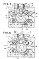
- Fig. 5 is an enlarged sectional view of the valve chamber portion of Fig. 4, with the valve element in a closed position; and
- Fig. 6 is a view, similar to Fig. 5, but showing the valve element moved to its maximum downstream position under the influence of a high upstream pressure.
- Referring to Figs. 1 to 4, a
ball valve 10 comprises a housing orbody 12 formed of a pair of co-operating first andsecond body components housing 12 defines a cylindrical,internal valve chamber 18 which carries a rotatably mounted valve element orball member 20 and co-operating seat orseal assemblies ball member 20 is arranged to be rotated between open and closed positions by ahandle 26 suitably connected to theball 20 through astem assembly 28. - In particular, the
first body component 14 includes a generally rectangularfirst end portion 30 which has a pair of outwardly extendingflange sections second end portion 36 is axially aligned with thefirst end portion 30. As best shown in Fig. 4, a generallycylindrical opening 40 extends axially inwardly from the first end ofbody component 14 and partly defines thevalve chamber 18. The opening 40 terminates in a generally transversely extendingend wall 42 which defines a first end ofvalve chamber 18. An enlargedcounterbore 44 is formed about the inlet end of the opening 40 for reasons to be described. - Extending axially into the
body component 14 from the second end is acylindrical flow passage 48 which connects with and is axially aligned with thevalve chamber 18. Thepassage 48 has a reduced diameterinner end portion 50 and a larger diameterouter end portion 52. Means are provided to permit thepassage 48 to be connected to fluid flow lines and the like. Many different types of conventional connecting means could be used. As shown, however, the large diameter portion of theflow passage 48 is provided with female pipe threads for this purpose. - Closely surrounding the
inner end 50 ofpassage 48 is asleeve section 54 which extends axially into thevalve chamber 18. Thesleeve section 54 in combination with the outer wall of opening 40 defines an axially open annular recess 56 (Fig. 5). - Formed integrally with the
rectangular end portion 30 ofbody component 14 is a generally cylindrical bonnet portion 58. As illustrated, the bonnet portion 58 is provided withexternal threads 62 to permit the valve to be panel-mounted, if desired. - Formed axially through the bonnet portion 58 transversely to the
valve chamber 18 is a stem-receivingopening 60. Theopening 60 leads to the exterior of the body through ashoulder 65 on a radially inwardly extending circular flange portion 64. -
Body component 16 has a generally hexagonal configuration with a pair of laterally extendingflange sections flange sections flange sections body component 14. The flange sections are provided with aligned openings to allow thebody components socket head capscrews 82 andnuts 84 as shown. In addition, theflange sections capscrews 82. Recesses provided onflanges socket head capscrews 82 are similar. - As best shown in Figs. 4 and 5, the inner end of
body component 16 is arranged to engage with the first end ofbody component 14 and close the outer end of thevalve chamber 18. Thebody component 16 has an axially extendingflow passage 86. Theflow passage 86 has alarge diameter section 88 and an inner,smaller diameter section 90 which opens axially to thevalve chamber 18. As shown, the outer end ofpassageway 86 is provided with female pipe threads for permitting connection of the valve to associated flow lines. - The
inner end wall 91 of thebody component 16 is provided with radially spaced and circumferentially continuous second andthird sleeve sections 92 and 94 (Fig. 5). The second orinner sleeve section 92 is positioned closely about theopening 90 and extends axially of thevalve chamber 18 towards thesleeve section 54. The third orouter sleeve section 94 is located radially outwardly of thesecond sleeve section 92 and, in combination therewith, defines an axially open annular recess or groove 96 which is aligned with and generally of the same size as theannular recess 56. Theinner wall 98 of theouter sleeve section 94 is preferably located at a diameter corresponding to the diameter of opening 40 which defines thevalve chamber 18. Theouter wall 100 of thesleeve section 94 is spaced radially inwardly of thecounterbore 44 of opening 40 to define a circumferentiallycontinuous chamber 102. Themating body components ring 104 in thechamber 102. Blow-out of the O-ring 104 is prevented by a back-upring 106 located in thechamber 102 in engagement with the end face ofbody component 16. - Of significance to the present invention is the seat or seal arrangement relative to
ball 20. As shown,ball 20 has acentral passage 100 which, as is conventional, can be rotated into alignment with theflow passages ball 20 is mounted axially within thevalve chamber 18 between opposedseal ring members only seal ring 112 will be described in detail and the description thereof is equally applicable toseal ring 114. As shown in Fig. 5,seal ring 112 comprises a solid annular body formed from a suitable resilient material, such as polyethylene, PTFE, or the like depending upon the pressures and/or other environmental conditions to which the seal ring is to be subjected. Thering 112 is sized so as to be closely but slidably received in therecess 56. Theseal face 116 of thering 112 is contoured to closely engage theball 20 and has a radius on theseal face 116 substantially equal to the radius of the ball. - The inner end face of each seat ring 112,114 is provided with radially inner and outer circumferentially continuous short walls or lips 113 (Fig. 6). The
lips 113 are integral with the body of the respective seat ring and extend axially therefrom. An O-ring lips 113. Preferably, thelips 113 are shorter than the normal or uncompressed thickness of the associated O-ring lips 113 will subsequently be expalined in more detail but their primary purpose is to radially confine the O-ring 120 and prevent extrusion of the O-ring under high pressure conditions. - The
seal ring 112 and theopposed seal ring 114 are both maintained under a bias towards the ball by the O-rings annular recesses ball 20 such that, in the position shown in Fig. 5 the rings sealingly engage the ball with a predetermined contact force sufficient to ensure sealing under low pressure conditions. - Fig. 6 shows the ball and the seal ring relationships under conditions of high pressure. Specifically, the
ball 20 is mounted so that it can move axially of the valve chamber in response to high upstream pressure conditions. As shown, with a high pressure present inflow passage 48, theball 20 is moved towardsseal ring 114 thereby increasing the seal pressure between the seal face ofring 114 and the ball. With the increased pressure acting againstring 114, the ring moves intorecess 96, compressing O-ring 122. During compression of O-ring 122, the O-ring is confined radially by thelips 113. The compression of the O-ring 122 applies radial forces to thelips 113, causing them to engage the walls of therecess 96 more tightly. This relationship prevents extrusion of the O-ring 122 about theseat ring 114. - As compression of the downstream O-
ring 114 takes place, theupstream seat ring 112 moves with theball 20 for a short distance. However, with continued movement of the ball, the seal betweenseal ring 112 and the ball is broken and the valve chamber area surrounding the ball is subjected to the increased pressure. The O-rings respective recesses inner sleeve sections - It is important that the seal rings 112 and 114 are substantially fully confined, and enclosed about both their inner and outer surfaces when they are in their maximum loaded conditions. By so confining the seat rings, cold flow and distortion of the seal ring at the downstream end under high pressure conditions is eliminated. The forces acting on the seats are thus substantially pure compression loads which the materials from which such seats are formed can withstand better than bending or tension. Also, the seals, the O-rings, and the ball seat cavities are identical to one another and the valve is therefor bi-directional. That is, it can be used with either of the
flow passages flow passage 86 is the inlet passage, theball 20 moves towardsseat ring 112 under high pressure conditions in the same manner as previously discussed with respect toseat ring 114 whenpassage 48 is serving as the inlet. - A further feature is the overall construction and arrangement of the
stem assembly 28. As previously discussed,stem assembly 28 is arranged to be blow-out proof in that the stem and related elements are totally confined within the valve body by the previously mentioned flange 64. Additionally, the assembly provides non-wetted bearing surfaces for the stem. - Specifically, stem
assembly 28 includes a unitary, one-piece stem member 130 having a reduced diameterlower end portion 132.Portion 132 is provided with a pair ofoppositely facing flats 134 which are freely received in an arcuate, flatsided groove 136 formed in the ball 20 (Figs. 4 and 5). The recess or groove 136 inball 20 provides a driving connection between thestem 130 and theball 20 while permitting the ball to be free to move in the downstream direction under the influence of high upstream pressures when the valve is in the closed position. For this reason,groove 136 extends transversely of theball passage 110. -
Stem 130 further includes a radially extending integral flange 138 (Fig. 4).Flange 138 has a diameter only slightly less than the diameter ofopening 60. Also carried outstem 130 is aradially extending shoulder 140. Preferably the upper surface ofshoulder 140, extends perpendicular to the axis ofstem 130, while the lower surface is tapered as shown. The relationship betweenflange 138,shoulder 140 and the flange 64 on the upper end of opening 60 provides enclosed entrapment chambers for the bearing and seal elements which will subsequently be described. - The upper end of
stem 130 has a reduceddiameter portion 144 which extends outwardly through flange 64 to the exterior of thebody component 14.Handle 26 is connected to the upper end of thestem portion 144 in any convenient manner such as through the use of asetscrew 146. - As shown, handle 26 is moulded from plastic and has a generally oval, elonagated configuration, best shown in Fig. 1. The oval configuration provides a readily visible indication of the position of the valve. Preferably, the
handle 26 includes ametal insert 148 which is moulded into the plastic of the handle body. Preferably, theinsert 148 has anintegral stop portion 150 which is arranged to engage suitable stop surfaces (not shown) formed in the outer end of bonnet portion 58. Also, theinsert 148 has opposed flats on its sides such that, if the handle is broken or shattered, the valve could be operated by applying a wrench to the insert. - Referring again to the operating
stem assembly 28, thestem member 130 is sealed and guided by resilient rings 154,156 and 157, and an O-ring 158.Ring 154 is captured between theupper stem flange 138 and theshoulder 65. This ring is preferably made from a relatively, stiff but resilient material such as a filled PTFE, or the like.Rings flange 138 on opposite sides of O-ring 158. The spacing between the underside offlange 138 andshoulder 140 is related to the total thickness of rings 156,157 and 158 so as to provide a slight precompression on O-ring 158. - The main guiding and bearing surfaces for the
stem 130 are provided byrings ring 158 at the location shown allows the bearing and guide surfaces provided byrings - Because the
stem 130 is totally captured within theopening 60 and is not held therein by threaded or bolted connections, the valve is generally considered to to blow-out proof. In addition, because of the arrangement of the stem it must be assembled from the exterior ofbody component 14 by being inserted into thebore 44 from the outer end thereof prior to attachment ofbody component 16. Because of the overall length of thestem 130 and the diameter of opening 40, thebody component 14 is provided with a relief area orcutout 160 which provides a space for the insertion ofstem 130. - The invention has been described with reference to a preferred embodiment. Alterations and modifications are included insofar as they come within the scope of the claims.
Claims (15)
Priority Applications (1)
| Application Number | Priority Date | Filing Date | Title |
|---|---|---|---|
| EP91202603A EP0474318B1 (en) | 1987-02-06 | 1988-02-04 | Ball valve |
Applications Claiming Priority (2)
| Application Number | Priority Date | Filing Date | Title |
|---|---|---|---|
| US11753 | 1987-02-06 | ||
| US07/011,753 US4762301A (en) | 1987-02-06 | 1987-02-06 | Compact multi-service ball valve |
Related Child Applications (2)
| Application Number | Title | Priority Date | Filing Date |
|---|---|---|---|
| EP91202603A Division EP0474318B1 (en) | 1987-02-06 | 1988-02-04 | Ball valve |
| EP91202603.6 Division-Into | 1988-02-04 |
Publications (2)
| Publication Number | Publication Date |
|---|---|
| EP0278675A2 true EP0278675A2 (en) | 1988-08-17 |
| EP0278675A3 EP0278675A3 (en) | 1989-09-20 |
Family
ID=21751833
Family Applications (2)
| Application Number | Title | Priority Date | Filing Date |
|---|---|---|---|
| EP91202603A Expired - Lifetime EP0474318B1 (en) | 1987-02-06 | 1988-02-04 | Ball valve |
| EP88300930A Withdrawn EP0278675A3 (en) | 1987-02-06 | 1988-02-04 | Ball valve |
Family Applications Before (1)
| Application Number | Title | Priority Date | Filing Date |
|---|---|---|---|
| EP91202603A Expired - Lifetime EP0474318B1 (en) | 1987-02-06 | 1988-02-04 | Ball valve |
Country Status (7)
| Country | Link |
|---|---|
| US (1) | US4762301A (en) |
| EP (2) | EP0474318B1 (en) |
| JP (1) | JP2809399B2 (en) |
| CA (1) | CA1292463C (en) |
| DE (1) | DE3855241T2 (en) |
| GB (1) | GB2201231B (en) |
| HK (1) | HK131693A (en) |
Cited By (2)
| Publication number | Priority date | Publication date | Assignee | Title |
|---|---|---|---|---|
| WO2006040592A1 (en) * | 2004-10-16 | 2006-04-20 | Enovate Systems Limited | Ball valve |
| NO339455B1 (en) * | 2004-12-21 | 2016-12-12 | Fisher Controls Int Llc | Universal fluid valve body |
Families Citing this family (21)
| Publication number | Priority date | Publication date | Assignee | Title |
|---|---|---|---|---|
| US5540414A (en) * | 1994-05-03 | 1996-07-30 | Taco, Inc. | Actuator and zone valve |
| DE4416039C1 (en) * | 1994-05-06 | 1995-08-31 | Freudenberg Carl Fa | Mixer control valve |
| US5730420A (en) * | 1995-09-15 | 1998-03-24 | Parker-Hannifin Corporation | Ball valve having one-piece packing |
| US5577709A (en) * | 1995-10-17 | 1996-11-26 | Henry Valve Company | Stem seal configuration for ball valves |
| US5904337A (en) * | 1996-07-31 | 1999-05-18 | Prolon Inc. | Ball valve seat and seal apparatus and assembly method |
| US5778759A (en) * | 1996-11-15 | 1998-07-14 | Phoenix Energy Products, Incorporated | Self-aligning piston rod |
| US5927685A (en) * | 1998-03-16 | 1999-07-27 | Jvp, Inc. | Sealing device for a valve stem of a valve |
| US6095493A (en) * | 1999-01-15 | 2000-08-01 | Velan Inc. | High pressure valve |
| GB2363184B (en) * | 1999-09-06 | 2003-03-19 | Alan Frederick Rees | Stemless large bore ball valve mk 6 |
| US6206023B1 (en) | 2000-04-27 | 2001-03-27 | Nordstrom Valves, Inc. | Ball valve including seat retainer securing means and method for forming the same |
| US7093819B1 (en) * | 2004-07-01 | 2006-08-22 | Mogas Industries, Inc. | Ball valve with shear bushing and integral bracket for stem blowout protection |
| US7527484B2 (en) * | 2006-07-06 | 2009-05-05 | Lg Electronics Inc. | Muffler of scroll compressor |
| CN102620005A (en) * | 2012-04-13 | 2012-08-01 | 江苏泰伯铸造有限公司 | Low-operating torque and low-leakage floating ball valve |
| RU2517467C2 (en) * | 2012-05-23 | 2014-05-27 | Открытое акционерное общество "Ракетно-космическая корпорация "Энергия" имени С.П. Королева" | Ball valve |
| DE102014015882A1 (en) * | 2014-10-27 | 2016-04-28 | Audi Ag | Exhaust gas turbocharger for an internal combustion engine and method for producing an exhaust gas turbocharger |
| RU2599405C2 (en) * | 2015-02-09 | 2016-10-10 | Открытое акционерное общество "Ракетно-космическая корпорация "Энергия" имени С.П. Королева" | Ball valve |
| EP3242061B1 (en) * | 2016-05-04 | 2019-03-06 | Hyundai Motor Company | Coolant control valve unit having sealing structure |
| CN111720591A (en) * | 2019-03-18 | 2020-09-29 | 罗伯特·博世有限公司 | Distribution valve and refrigeration system |
| US11009136B2 (en) * | 2019-05-08 | 2021-05-18 | Habonim Industrial Valves & Actuators Ltd. | Bidirectional cryogenic firesafe floating ball valve |
| US11280414B2 (en) * | 2020-07-27 | 2022-03-22 | Hanon Systems | Plug valve hard seals on cylinder wall |
| US11454327B2 (en) * | 2020-08-07 | 2022-09-27 | Commando Pressure Control, Inc. | Methods and systems associated with a high pressure valve system |
Citations (4)
| Publication number | Priority date | Publication date | Assignee | Title |
|---|---|---|---|---|
| US3357679A (en) * | 1963-10-31 | 1967-12-12 | Acf Ind Inc | Multi-material elastomer seal |
| US3598363A (en) * | 1969-09-04 | 1971-08-10 | Golconda Corp | Ball valve |
| US3642248A (en) * | 1969-05-07 | 1972-02-15 | Allen & Co Fof Proprietary Fun | Sealing mechanism |
| US4258900A (en) * | 1979-05-21 | 1981-03-31 | Kamyr Valves, Inc. | Structure maintaining seats against ball valves |
Family Cites Families (23)
| Publication number | Priority date | Publication date | Assignee | Title |
|---|---|---|---|---|
| GB1050981A (en) * | ||||
| DE1151417B (en) * | 1954-12-03 | 1963-07-11 | Neue Argus Gmbh | Stopcock with spherical plug and sealing by ring piston |
| GB799339A (en) * | 1955-04-19 | 1958-08-06 | Neue Argus Gmbh | Rotary spherical cock |
| US3033227A (en) * | 1960-03-25 | 1962-05-08 | Walworth Co | Ball valve |
| US3161204A (en) * | 1962-05-11 | 1964-12-15 | Sr Henry A Roy | Ball valves |
| US3288430A (en) * | 1964-05-18 | 1966-11-29 | Hills Mccanna Co | Ball valve unit |
| DE1290776B (en) * | 1965-05-24 | 1969-03-13 | Hartmann Patentverwertung Gmbh | Cock with a plug mounted in a split housing |
| US3350057A (en) * | 1965-06-17 | 1967-10-31 | Mueller Co | Retainer ring and thrust washer arrangement for valves or the like |
| US3508738A (en) * | 1966-05-02 | 1970-04-28 | Acf Ind Inc | Valve |
| GB1142441A (en) * | 1967-04-14 | 1969-02-05 | Masheder Design Studies Ltd | Improvements in ball valves |
| US3497177A (en) * | 1967-11-02 | 1970-02-24 | Eldon E Hulsey | Seat and seal assembly for valves |
| GB1216354A (en) * | 1968-10-10 | 1970-12-23 | Hills Mccanna Co | Ball valves |
| US3656711A (en) * | 1970-08-17 | 1972-04-18 | Encon Mfg Co | Thermoset plastic ball valve |
| US3678956A (en) * | 1970-12-21 | 1972-07-25 | Lockheed Aircraft Corp | Redundant seal ball valve |
| JPS4830979U (en) * | 1971-08-17 | 1973-04-16 | ||
| US4111393A (en) * | 1977-07-20 | 1978-09-05 | Acf Industries, Incorporated | Ball valve seat assembly having a removably mounted face seal insert |
| US4548385A (en) * | 1979-12-18 | 1985-10-22 | Quality Controls, Inc. | Flexible seal for rotor valves |
| US4479513A (en) * | 1981-08-28 | 1984-10-30 | Whitey Co. | High pressure ball valve |
| JPS58122073A (en) * | 1982-01-18 | 1983-07-20 | Matsushita Electric Ind Co Ltd | Atomizing device |
| BG36297A1 (en) * | 1983-02-11 | 1984-10-15 | Kolev | Stuffing- box for spheric crane |
| JPS59205079A (en) * | 1983-05-04 | 1984-11-20 | Toyo Kako Kk | Plastics valve and manufacturing method thereof |
| US4580763A (en) * | 1984-01-26 | 1986-04-08 | Velan, Inc. | Seal-seat for use in ball valves |
| US4684105A (en) * | 1985-11-21 | 1987-08-04 | Haas Ii Carroll J | Ball valve |
-
1987
- 1987-02-06 US US07/011,753 patent/US4762301A/en not_active Expired - Fee Related
-
1988
- 1988-02-04 EP EP91202603A patent/EP0474318B1/en not_active Expired - Lifetime
- 1988-02-04 JP JP63024846A patent/JP2809399B2/en not_active Expired - Lifetime
- 1988-02-04 DE DE3855241T patent/DE3855241T2/en not_active Expired - Fee Related
- 1988-02-04 EP EP88300930A patent/EP0278675A3/en not_active Withdrawn
- 1988-02-04 GB GB8802542A patent/GB2201231B/en not_active Expired - Fee Related
- 1988-02-05 CA CA000558274A patent/CA1292463C/en not_active Expired - Fee Related
-
1993
- 1993-12-02 HK HK1316/93A patent/HK131693A/en not_active IP Right Cessation
Patent Citations (4)
| Publication number | Priority date | Publication date | Assignee | Title |
|---|---|---|---|---|
| US3357679A (en) * | 1963-10-31 | 1967-12-12 | Acf Ind Inc | Multi-material elastomer seal |
| US3642248A (en) * | 1969-05-07 | 1972-02-15 | Allen & Co Fof Proprietary Fun | Sealing mechanism |
| US3598363A (en) * | 1969-09-04 | 1971-08-10 | Golconda Corp | Ball valve |
| US4258900A (en) * | 1979-05-21 | 1981-03-31 | Kamyr Valves, Inc. | Structure maintaining seats against ball valves |
Cited By (4)
| Publication number | Priority date | Publication date | Assignee | Title |
|---|---|---|---|---|
| WO2006040592A1 (en) * | 2004-10-16 | 2006-04-20 | Enovate Systems Limited | Ball valve |
| US7963339B2 (en) | 2004-10-16 | 2011-06-21 | Enovate Systems Limited | Bearing mounted ball valve and method of use |
| NO338761B1 (en) * | 2004-10-16 | 2016-10-17 | Enovate Systems Ltd | Improved ball valve |
| NO339455B1 (en) * | 2004-12-21 | 2016-12-12 | Fisher Controls Int Llc | Universal fluid valve body |
Also Published As
| Publication number | Publication date |
|---|---|
| EP0474318B1 (en) | 1996-04-24 |
| GB2201231B (en) | 1991-05-01 |
| DE3855241D1 (en) | 1996-05-30 |
| CA1292463C (en) | 1991-11-26 |
| HK131693A (en) | 1993-12-10 |
| EP0278675A3 (en) | 1989-09-20 |
| GB8802542D0 (en) | 1988-03-02 |
| GB2201231A (en) | 1988-08-24 |
| DE3855241T2 (en) | 1996-11-28 |
| EP0474318A3 (en) | 1992-04-01 |
| JP2809399B2 (en) | 1998-10-08 |
| US4762301A (en) | 1988-08-09 |
| EP0474318A2 (en) | 1992-03-11 |
| JPS63270984A (en) | 1988-11-08 |
Similar Documents
| Publication | Publication Date | Title |
|---|---|---|
| EP0474318B1 (en) | Ball valve | |
| EP0244185B1 (en) | Bellows valve | |
| US4304261A (en) | Valve | |
| US4363465A (en) | Extreme temperature, high pressure balanced, rising stem gate valve with super preloaded, stacked, solid lubricated, metal-to-metal seal | |
| US4685488A (en) | Ball valve | |
| US4180097A (en) | Mud pump valve | |
| US5490537A (en) | Prosthesis air valve assembly and tool therefor | |
| CA2233184A1 (en) | Dual valve fitting for enabling quick measurement of pressure | |
| US5592965A (en) | Valve stop changer | |
| US6220290B1 (en) | Double block and bleed ball valves including retainer components | |
| US4264054A (en) | Metal-to-metal seat hub seals | |
| EP0323448A2 (en) | Valves for fluids | |
| US4541608A (en) | High pressure shut-off valve | |
| EP0774090B1 (en) | Valve assembly having improved valve seat | |
| GB2421067A (en) | Ball valve assembly | |
| US4556196A (en) | Method and apparatus for sealing valve stems | |
| US5029812A (en) | Valve seat mechanism | |
| EP0029732B1 (en) | Ceramic ball valve | |
| US4630629A (en) | Valve with compressible valve stem and valve body seals | |
| US5284320A (en) | Surface valve with pressure energized seal and gear actuation | |
| EP0648962B1 (en) | Ball valve for a refrigeration system | |
| EP0305177B1 (en) | Relief valve | |
| US7988127B2 (en) | Valve with self-expanding seals | |
| EP0447707A1 (en) | Valve with removable insert | |
| US5715740A (en) | Combined piston rod alignment and sealing assembly for fluid actuator cylinders |
Legal Events
| Date | Code | Title | Description |
|---|---|---|---|
| PUAI | Public reference made under article 153(3) epc to a published international application that has entered the european phase |
Free format text: ORIGINAL CODE: 0009012 |
|
| AK | Designated contracting states |
Kind code of ref document: A2 Designated state(s): BE DE FR NL |
|
| PUAL | Search report despatched |
Free format text: ORIGINAL CODE: 0009013 |
|
| AK | Designated contracting states |
Kind code of ref document: A3 Designated state(s): BE DE FR NL |
|
| 17P | Request for examination filed |
Effective date: 19900315 |
|
| 17Q | First examination report despatched |
Effective date: 19901127 |
|
| STAA | Information on the status of an ep patent application or granted ep patent |
Free format text: STATUS: THE APPLICATION IS DEEMED TO BE WITHDRAWN |
|
| 18D | Application deemed to be withdrawn |
Effective date: 19911221 |