EP0278632A1 - Carpet cleaning apparatus - Google Patents
Carpet cleaning apparatus Download PDFInfo
- Publication number
- EP0278632A1 EP0278632A1 EP88300671A EP88300671A EP0278632A1 EP 0278632 A1 EP0278632 A1 EP 0278632A1 EP 88300671 A EP88300671 A EP 88300671A EP 88300671 A EP88300671 A EP 88300671A EP 0278632 A1 EP0278632 A1 EP 0278632A1
- Authority
- EP
- European Patent Office
- Prior art keywords
- carpet
- cleaning
- attachment
- wand
- reservoir
- Prior art date
- Legal status (The legal status is an assumption and is not a legal conclusion. Google has not performed a legal analysis and makes no representation as to the accuracy of the status listed.)
- Withdrawn
Links
Images


Classifications
-
- A—HUMAN NECESSITIES
- A47—FURNITURE; DOMESTIC ARTICLES OR APPLIANCES; COFFEE MILLS; SPICE MILLS; SUCTION CLEANERS IN GENERAL
- A47L—DOMESTIC WASHING OR CLEANING; SUCTION CLEANERS IN GENERAL
- A47L11/00—Machines for cleaning floors, carpets, furniture, walls, or wall coverings
- A47L11/29—Floor-scrubbing machines characterised by means for taking-up dirty liquid
-
- A—HUMAN NECESSITIES
- A47—FURNITURE; DOMESTIC ARTICLES OR APPLIANCES; COFFEE MILLS; SPICE MILLS; SUCTION CLEANERS IN GENERAL
- A47L—DOMESTIC WASHING OR CLEANING; SUCTION CLEANERS IN GENERAL
- A47L11/00—Machines for cleaning floors, carpets, furniture, walls, or wall coverings
- A47L11/34—Machines for treating carpets in position by liquid, foam, or vapour, e.g. by steam
-
- A—HUMAN NECESSITIES
- A47—FURNITURE; DOMESTIC ARTICLES OR APPLIANCES; COFFEE MILLS; SPICE MILLS; SUCTION CLEANERS IN GENERAL
- A47L—DOMESTIC WASHING OR CLEANING; SUCTION CLEANERS IN GENERAL
- A47L11/00—Machines for cleaning floors, carpets, furniture, walls, or wall coverings
- A47L11/40—Parts or details of machines not provided for in groups A47L11/02 - A47L11/38, or not restricted to one of these groups, e.g. handles, arrangements of switches, skirts, buffers, levers
- A47L11/4052—Movement of the tools or the like perpendicular to the cleaning surface
- A47L11/4058—Movement of the tools or the like perpendicular to the cleaning surface for adjusting the height of the tool
-
- A—HUMAN NECESSITIES
- A47—FURNITURE; DOMESTIC ARTICLES OR APPLIANCES; COFFEE MILLS; SPICE MILLS; SUCTION CLEANERS IN GENERAL
- A47L—DOMESTIC WASHING OR CLEANING; SUCTION CLEANERS IN GENERAL
- A47L7/00—Suction cleaners adapted for additional purposes; Tables with suction openings for cleaning purposes; Containers for cleaning articles by suction; Suction cleaners adapted to cleaning of brushes; Suction cleaners adapted to taking-up liquids
- A47L7/0004—Suction cleaners adapted to take up liquids, e.g. wet or dry vacuum cleaners
- A47L7/0009—Suction cleaners adapted to take up liquids, e.g. wet or dry vacuum cleaners with means mounted on the nozzle; nozzles specially adapted for the recovery of liquid
-
- A—HUMAN NECESSITIES
- A47—FURNITURE; DOMESTIC ARTICLES OR APPLIANCES; COFFEE MILLS; SPICE MILLS; SUCTION CLEANERS IN GENERAL
- A47L—DOMESTIC WASHING OR CLEANING; SUCTION CLEANERS IN GENERAL
- A47L7/00—Suction cleaners adapted for additional purposes; Tables with suction openings for cleaning purposes; Containers for cleaning articles by suction; Suction cleaners adapted to cleaning of brushes; Suction cleaners adapted to taking-up liquids
- A47L7/0004—Suction cleaners adapted to take up liquids, e.g. wet or dry vacuum cleaners
- A47L7/0023—Recovery tanks
- A47L7/0028—Security means, e.g. float valves or level switches for preventing overflow
-
- A—HUMAN NECESSITIES
- A47—FURNITURE; DOMESTIC ARTICLES OR APPLIANCES; COFFEE MILLS; SPICE MILLS; SUCTION CLEANERS IN GENERAL
- A47L—DOMESTIC WASHING OR CLEANING; SUCTION CLEANERS IN GENERAL
- A47L7/00—Suction cleaners adapted for additional purposes; Tables with suction openings for cleaning purposes; Containers for cleaning articles by suction; Suction cleaners adapted to cleaning of brushes; Suction cleaners adapted to taking-up liquids
- A47L7/0004—Suction cleaners adapted to take up liquids, e.g. wet or dry vacuum cleaners
- A47L7/0023—Recovery tanks
- A47L7/0038—Recovery tanks with means for emptying the tanks
-
- A—HUMAN NECESSITIES
- A47—FURNITURE; DOMESTIC ARTICLES OR APPLIANCES; COFFEE MILLS; SPICE MILLS; SUCTION CLEANERS IN GENERAL
- A47L—DOMESTIC WASHING OR CLEANING; SUCTION CLEANERS IN GENERAL
- A47L7/00—Suction cleaners adapted for additional purposes; Tables with suction openings for cleaning purposes; Containers for cleaning articles by suction; Suction cleaners adapted to cleaning of brushes; Suction cleaners adapted to taking-up liquids
- A47L7/0004—Suction cleaners adapted to take up liquids, e.g. wet or dry vacuum cleaners
- A47L7/0042—Gaskets; Sealing means
Definitions
- This invention relates to carpet cleaning apparatus, and more particularly to a fluid-delivering attachment for a wet-and-dry vacuum cleaner.
- carpet cleaning apparatus which will spray or othervise deliver a cleaning fluid to the region of carpet in advance of the moving suction nozzle. Dirt that would not be removed by suction alone is taken up by the cleaning fluid in solution or suspension and the cleaning fluid is then extracted by the suction nozzle. It is possible in this manner to clean carpet and leave it almost dry.
- One form of known cleaning apparatus comprises a suction unit which stands on rollers, casters or the like.
- the suction unit contains, in addition to the vacuum pump, a receptacle for extracted fluid and dirt; a reservoir for cleaning fluid; and a cleaning fluid pump.
- a suction hose is connected to the vacuum unit and to a generally conventional wand, which is adapted to be held with the hands, and is formed at the opposite end with a suction nozzle.
- a cleaning fluid pipe extends from the vacuum unit to the nozzle in such a manner that fluid from the reservoir, pressurized by the pump, is deposited on the carpet immediately in front of the moving nozzle.
- a second type of known apparatus differs from the first in that there is no flexible suction hose.
- the assembly containing the vacuum unit, water and dirt receptacle, pump and water reservoir is provided with an upright handle and is designed to be maneuverable over the carpet.
- the suction nozzle and water delivery spout are formed integrally with the main assembly.
- the reservoir and fluid pump are combined in a single unit with the suction pump and dirt/water receptacle, which is an expensive, clumsy, and inflexible arrangement.
- the present invention comprises a carpet cleaning attachment, for use with existing carpet cleaning devices having a flexible attachment hose and a unit capable of extracting both wet and dry materials, the attachment comprising means defining a hollow, elongated, hand-held wand configured at a connection end thereof for connection to the hose and provided at the opposite end with a suction nozzle for being moved across a carpet; cleaning fluid reservoir means mounted on the wand; and cleaning fluid delivery means carried on the wand for delivering cleaning fluid from the reservoir to a region of the carpet in advance of the moving nozzle.
- the wand is provided with ground engaging means for controlling the attitude of the wand relative to the carpet surface.
- the ground engaging means comprises roller means displaceable relative to the wand into a transport position and an operating position.
- the cleaning fluid delivery system includes an electrically operated fluid pump for spraying fluid onto the carpet.
- the cleaning fluid system includes a manually operable pump for creating a charge of compressed air above cleaning fluid contained in the reservoir.
- the carpet cleaning attachments in accordance with this invention can be arranged for direct coupling to the suction hose of one or more commercially available wet and dry vacuum cleaning units.
- the cost of the attachments should be considerably less than that of previously known dedicated carpet cleaning apparatus and the wet and dry vacuum unit can be used for a variety of other purposes when not employed with the attachment.
- a carpet cleaning attachment according to one embodiment of this invention which is intended to be used with any one of a variety of commercially available wet and dry vacuum cleaners.
- a generally tubular wand 10 is formed at its upper end with a stepped portion 12 which receives a hose connector 14 held in place by spring clip 16.
- the connector 14 is engageable as a push-fit with the suction hose (not shown) of the vacuum cleaner.
- the nozzle is held in place by means of a further spring clip 24.
- the nozzle 22 is fan-shaped and defines a relatively narrow transverse nozzle opening 26.
- a pair of rollers 28 are mounted coaxially on a roller arm 30.
- the arm 30 is pivotally mounted upon axle 32 for movement relative to the support portion 18 from a transport position in which the rollers 28 are partly received within a curved recess 34 of the support portion, to a working position in which the arm 30 is held at approximately 90° to the length of the wand through engagement of an abutment surface 36 on the arm with the support portion 18.
- the attachment With the roller arm 30 in the working position, and both the suction nozzle opening 26 and rollers 28 in contact with the carpet surface, the attachment is held at the optimum working angle of approximately 45°, for being moved across the carpet in the direction labeled D in Fig. 1.
- the level of the carpet surface is shown in Fig. 1 at 38, by way of illustration.
- the support portion 18 defines a projecting platform 40 upon which rests a clean water reservoir 42.
- the reservoir extends over most of the length of the wand and has side wings 44 which partially encircle the wand.
- At the bottom of the reservoir 42 there is formed an aperture 46 into which is sealed a check valve unit 48.
- the check valve unit 48 comprises a cylindrical body 50 with an annular flange 52 which abuts the lower edge of the reservoir through seal 54.
- a sleeve 56 contained within the body has a central bore 58 accommodating a valve member 60 urged through compression spring 62 into engagement with valve seat 64.
- the body 50 is received within a port 66 of the support portion 18 with a water tight seal being assured by means of an O-ring carried in an annular recess 68 of the body.
- the support portion 18 is provided with an upstanding peg 70.
- a control valve 74 is mounted in the support portion 18 and comprises a cylindrical body 76 defining inlet and outlet ports 78 and 80, respectively.
- Inlet port 78 is connected through tubing with the bore 72 of the support portion.
- the body 76 accommodates a piston 82 having a washer 84 abutting (in the position shown in the Figure) a valve seat 86 formed around the outlet port 80.
- the piston is slidable upwardly from the position shown in Fig. 4 against the action of a compression spring 88 trapped between the piston 82 and an end cap 90.
- An elongated piston rod 92 extends through the cap 90 along the entire length of the wand 10.
- the piston rod 92 passes through a bracket 94 on the hose connector 14 and through an aperture in a control lever 96.
- the piston rod terminates in an enlarged head 98 and the control lever 96 is shaped so that finger pressure on the lever, tending to move it towards the hose connector 14, lifts the rod head 98 away from the bracket 94.
- washer 84 is moved away from valve seat 86, permitting water to flow from the inlet port 78 to the outlet port 80.
- a spray element 100 having a spigot 102 connected through tubing to the outlet port 80 of the control valve.
- the spray element 100 is adapted to provide a fan-shaped spray of water extending over generally the same transverse width as the nozzle opening 26.
- the reservoir 42 is provided at its upper end with a manually operated pump assembly 104.
- This pump assembly comprises a cylinder 106 extending into the reservoir and closed at its lower end by a one-way flap valve 108.
- a piston 110 is slidably mounted in the cylinder 106 and sealed with an O-ring 112.
- a piston rod 114 extends from the piston 110 to a shaped handle 116 seated on the upper surface of the reservoir.
- the pump assembly 104 is located within the reservoir by means of an integral collar 118.
- a locking mechanism is desirably included, by which rotation of the handle 116 through 90° releases the piston assembly for reciprocal motion.
- the reservoir is provided with a cap 120 which may be removed for refilling the reservoir.
- the cap comprises a cylindrical body 122 formed integrally with a dished portion 124 which engages an upturned flange 126 on the reservoir 42.
- a plunger 128 extends through the body portion 122 and is biased towards the position shown in Fig. 5 by means of a compression spring 130 acting between a central wall 132 of the body portion and a disc 134 carried on the inner end of the plunger.
- a disc 138 formed integrally with the plunger provides a location for an O-ring 139 which is in sealing engagement with the inner cylindrical surface of the body 122.
- the plunger moves outward, providing a visual indication of the increase in pressure.
- a predetermined pressure 40 psi in the described example
- the plunger has travelled a sufficient distance for the O-ring 139 to move into a rebate 140, allowing excess air pressure to be vented.
- the reservoir 42 is partly filled with water including, if desired, a suitable detergent or other additive.
- the handle 116 is freed from the reservoir and reciprocated in a pumping action to establish a charge of compressed air above the water contained within the reservoir. It will be understood that in this pumping action, flap valve 108 operates as a one-way valve. When a sufficient pressure has been reached, the handle 116 is re-locked in position. With the suction hose of a wet-and-dry vacuum cleaner engaged with hose connector 14, the attachment is then moved slowly over the carpet to be cleaned. The rollers 28 assist the user in ensuring that the wand is held at the optimum angle to the carpet surface for efficient extraction by suction nozzle 26.
- Finger pressure on lever 96 serves, as described, to open control valve 74 so that water from the reservoir is delivered under pressure to spray element 100, and thus to the region of the carpet immediately in advance of the moving suction nozzle opening 26, as the attachment is moved in the direction D (Fig. 1).
- the described carpet cleaning attachment makes use of the vacuum unit, suction hose and dirt/water receptacle of the existing wet-and-dry vacuum cleaner.
- the attachment is therefore relatively light and easily maneuverable.
- the attachment is relatively inexpensive to manufacture. Because the delivery system for water or other cleaning fluid is positioned on the wand and thus very close to the point of delivery, it is possible to achieve high pressures, so the water spray can penetrate the pile of the carpet. This is in contrast with certain known apparatus, where the necessity for a long tube extending the length of the suction hose leads to very low delivery pressures.
- Fig. 6 there is shown a modified carpet cleaning attachment according to this invention. Parts and features which correspond to the embodiment of Figs. 1 to 5 have been given the same reference numerals and will not be described in detail.
- An electrically operated water pump 150 is mounted in the support portion 18 and is supplied with electrical power via a toggle switch 152 mounted in the hose connector 14.
- the attachment is provided with a supply lead (not shown) which is adapted for being connected with a socket for powered accessories provided on the existing vacuum cleaner.
- a cable winder 154 is provided on the accessory for easy storage of the supply cable.
- the pump 150 has an inlet (not shown) connected through flexible tubing with the bore 72, and an outlet (also not shown) connected through flexible tubing with the spray element 100.
- the reservoir 42 is of smaller size than in the manually operated embodiment, since there is no longer any need to accommodate a charge of compressible air above the contained water.
- a simple push-fit filler cap 156 can be employed.
- the reservoir is arranged to be removable for refilling, and a locking mechanism 158 for holding the reservoir in position is shown in the drawing.
- the locking mechanism comprises a cam 160, which is rotatable relative to the wand, about axle 162, through finger engagement with a peg 164. The cam engages a cam surface 166 formed on the reservoir so that, upon rotation of the cam, the reservoir is drawn tightly into position and thereby held against being dislodged.
- the modified carpet attachment is used in a manner analogous to that described above, with the delivery of water being controlled through switch 152.
- rollers or alternative ground engaging means such as a skid, to assist in controlling the attitude of the wand relative to the carpet surface is thought to be a desirable feature but should not be regarded as essential. It is preferred, therefore, that the present invention be limited not by the specific disclosure herein, but only by the appended claims.
Abstract
A carpet cleaning attachment, for use with existing carpet cleaning devices having a flexible attachment hose and a unit capable of extracting both wet and dry materials, the attachment comprising a hollow, elongated, hand-held wand (10) configured at a connection end thereof for connection to the hose and provided at the opposite end with a suction nozzle (22) for being moved across a carpet; a cleaning fluid reservoir (42) mounted on the wand(10); and a cleaning fluid delivery system carried on the wand (10) for delivering cleaning fluid from the reservoir (42) to a region of the carpet in advance of the moving nozzle.
Description
- This invention relates to carpet cleaning apparatus, and more particularly to a fluid-delivering attachment for a wet-and-dry vacuum cleaner.
- It is recognized that conventional vacuum cleaning devices will fail to remove from the carpet certain categories of dirt which can only satisfactorily be dealt with by the application of water or other cleaning fluid. Carpet cleaning apparatus has previously been provided which will spray or othervise deliver a cleaning fluid to the region of carpet in advance of the moving suction nozzle. Dirt that would not be removed by suction alone is taken up by the cleaning fluid in solution or suspension and the cleaning fluid is then extracted by the suction nozzle. It is possible in this manner to clean carpet and leave it almost dry.
- One form of known cleaning apparatus comprises a suction unit which stands on rollers, casters or the like. The suction unit contains, in addition to the vacuum pump, a receptacle for extracted fluid and dirt; a reservoir for cleaning fluid; and a cleaning fluid pump. A suction hose is connected to the vacuum unit and to a generally conventional wand, which is adapted to be held with the hands, and is formed at the opposite end with a suction nozzle. A cleaning fluid pipe extends from the vacuum unit to the nozzle in such a manner that fluid from the reservoir, pressurized by the pump, is deposited on the carpet immediately in front of the moving nozzle.
- A second type of known apparatus differs from the first in that there is no flexible suction hose. The assembly containing the vacuum unit, water and dirt receptacle, pump and water reservoir is provided with an upright handle and is designed to be maneuverable over the carpet. The suction nozzle and water delivery spout are formed integrally with the main assembly.
- While the known apparatus is efficient in cleaning carpets, there is a relatively high capital cost, and since domestic users are likely to clean carpets in this manner comparatively infrequently, purchase of the apparatus may not be an economic proposition.
- Also, in these known units the reservoir and fluid pump are combined in a single unit with the suction pump and dirt/water receptacle, which is an expensive, clumsy, and inflexible arrangement.
- There are now widely available so-called "wet-and-dry" vacuum cleaning devices which are capable of removing by suction not only dirt particles but also wet or liquid waste material. It is an object of this invention to provide attachments for use with such vacuum cleaning devices, to produce efficient and flexible carpet cleaning apparatus, at a cost which is modest compared to the dedicated carpet cleaning apparatus as described above.
- Accordingly, the present invention comprises a carpet cleaning attachment, for use with existing carpet cleaning devices having a flexible attachment hose and a unit capable of extracting both wet and dry materials, the attachment comprising means defining a hollow, elongated, hand-held wand configured at a connection end thereof for connection to the hose and provided at the opposite end with a suction nozzle for being moved across a carpet; cleaning fluid reservoir means mounted on the wand; and cleaning fluid delivery means carried on the wand for delivering cleaning fluid from the reservoir to a region of the carpet in advance of the moving nozzle.
- Advantageously, the wand is provided with ground engaging means for controlling the attitude of the wand relative to the carpet surface.
- Suitably, the ground engaging means comprises roller means displaceable relative to the wand into a transport position and an operating position.
- Advantageously, the cleaning fluid delivery system includes an electrically operated fluid pump for spraying fluid onto the carpet.
- In another form of the invention, the cleaning fluid system includes a manually operable pump for creating a charge of compressed air above cleaning fluid contained in the reservoir.
- It will be understood that the carpet cleaning attachments in accordance with this invention can be arranged for direct coupling to the suction hose of one or more commercially available wet and dry vacuum cleaning units. The cost of the attachments should be considerably less than that of previously known dedicated carpet cleaning apparatus and the wet and dry vacuum unit can be used for a variety of other purposes when not employed with the attachment.
- Other objects, features and advantages of the invention will be understood from the following description of embodiments thereof, with reference to the accompanying drawings, in which:
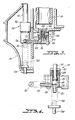
- Fig. 1 is an end view, partly in section, of a carpet cleaning attachment according to this invention;
- Fig. 2 is a front view of the attachment shown in Fig. 1;
- Fig. 3 is a detail view, on a larger scale, of part of the attachment shown in Fig. 1;
- Fig. 4 is a detail view, on a larger scale, of another part of the attachment shown in Fig. 1;
- Fig. 5 is an enlarged sectional view taken on line 5-5 of Fig. 2; and
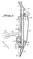
- Fig. 6 is an end view, partly in section, of a further carpet cleaning attachment according to this invention.
- Referring first to Fig. 1, there is shown a carpet cleaning attachment according to one embodiment of this invention which is intended to be used with any one of a variety of commercially available wet and dry vacuum cleaners.
- A generally
tubular wand 10 is formed at its upper end with astepped portion 12 which receives ahose connector 14 held in place by spring clip 16. Theconnector 14 is engageable as a push-fit with the suction hose (not shown) of the vacuum cleaner. Towards the lower end of thewand 10, there is formed anintegral support portion 18. This portion defines a downwardly directedrecess 20 in which is received the stub of asuction nozzle 22. The nozzle is held in place by means of afurther spring clip 24. As best seen in Fig. 2, thenozzle 22 is fan-shaped and defines a relatively narrowtransverse nozzle opening 26. - As seen in Figs. 1 and 2, a pair of
rollers 28 are mounted coaxially on aroller arm 30. Thearm 30 is pivotally mounted upon axle 32 for movement relative to thesupport portion 18 from a transport position in which therollers 28 are partly received within acurved recess 34 of the support portion, to a working position in which thearm 30 is held at approximately 90° to the length of the wand through engagement of anabutment surface 36 on the arm with thesupport portion 18. With theroller arm 30 in the working position, and both the suction nozzle opening 26 androllers 28 in contact with the carpet surface, the attachment is held at the optimum working angle of approximately 45°, for being moved across the carpet in the direction labeled D in Fig. 1. The level of the carpet surface is shown in Fig. 1 at 38, by way of illustration. - The
support portion 18 defines aprojecting platform 40 upon which rests aclean water reservoir 42. The reservoir extends over most of the length of the wand and hasside wings 44 which partially encircle the wand. At the bottom of thereservoir 42, there is formed anaperture 46 into which is sealed acheck valve unit 48. - As seen more clearly in Fig. 3, the
check valve unit 48 comprises acylindrical body 50 with anannular flange 52 which abuts the lower edge of the reservoir throughseal 54. A sleeve 56 contained within the body has acentral bore 58 accommodating avalve member 60 urged throughcompression spring 62 into engagement withvalve seat 64. Thebody 50 is received within aport 66 of thesupport portion 18 with a water tight seal being assured by means of an O-ring carried in anannular recess 68 of the body. Coaxially with theport 66, thesupport portion 18 is provided with anupstanding peg 70. - With the
reservoir 42 positioned on thesupport portion 18 as shown in the Figures, engagement of thepeg 70 with thevalve member 60 compresses thespring 62 and allows water from thereservoir 42 to pass through the valve, into theport 66 of the support portion. Then the water passes along abore 72 formed in thesupport portion 18 which runs from the vicinity of thepeg 70. If the reservoir is removed for refilling, thespring 62 acts to close the valve to prevent leakage. - Referring now to Fig. 4, a
control valve 74 is mounted in thesupport portion 18 and comprises a cylindrical body 76 defining inlet andoutlet ports Inlet port 78 is connected through tubing with thebore 72 of the support portion. The body 76 accommodates apiston 82 having awasher 84 abutting (in the position shown in the Figure) avalve seat 86 formed around theoutlet port 80. The piston is slidable upwardly from the position shown in Fig. 4 against the action of acompression spring 88 trapped between thepiston 82 and anend cap 90. Anelongated piston rod 92 extends through thecap 90 along the entire length of thewand 10. - As seen in Fig. 1, the
piston rod 92 passes through abracket 94 on thehose connector 14 and through an aperture in acontrol lever 96. The piston rod terminates in an enlargedhead 98 and thecontrol lever 96 is shaped so that finger pressure on the lever, tending to move it towards thehose connector 14, lifts therod head 98 away from thebracket 94. It will be seen in Fig. 4 that as thepiston rod 92 is lifted,washer 84 is moved away fromvalve seat 86, permitting water to flow from theinlet port 78 to theoutlet port 80. - In the
support portion 18, directly beneath thecontrol valve 74, there is mounted aspray element 100 having aspigot 102 connected through tubing to theoutlet port 80 of the control valve. Thespray element 100 is adapted to provide a fan-shaped spray of water extending over generally the same transverse width as thenozzle opening 26. - As shown in Fig. 1, the
reservoir 42 is provided at its upper end with a manually operatedpump assembly 104. This pump assembly comprises acylinder 106 extending into the reservoir and closed at its lower end by a one-way flap valve 108. Apiston 110 is slidably mounted in thecylinder 106 and sealed with an O-ring 112. Apiston rod 114 extends from thepiston 110 to a shapedhandle 116 seated on the upper surface of the reservoir. Thepump assembly 104 is located within the reservoir by means of anintegral collar 118. A locking mechanism is desirably included, by which rotation of thehandle 116 through 90° releases the piston assembly for reciprocal motion. - As seen in Figs. 2 and 5, the reservoir is provided with a
cap 120 which may be removed for refilling the reservoir. The cap comprises a cylindrical body 122 formed integrally with a dishedportion 124 which engages anupturned flange 126 on thereservoir 42. Aplunger 128 extends through the body portion 122 and is biased towards the position shown in Fig. 5 by means of acompression spring 130 acting between acentral wall 132 of the body portion and adisc 134 carried on the inner end of the plunger. Adisc 138 formed integrally with the plunger provides a location for an O-ring 139 which is in sealing engagement with the inner cylindrical surface of the body 122. As the pressure in the reservoir increases on pumping of thepump assembly 104, the plunger moves outward, providing a visual indication of the increase in pressure. At a predetermined pressure (40 psi in the described example) the plunger has travelled a sufficient distance for the O-ring 139 to move into arebate 140, allowing excess air pressure to be vented. - The manner of operation of the described apparatus can now be understood.
- The
reservoir 42 is partly filled with water including, if desired, a suitable detergent or other additive. Thehandle 116 is freed from the reservoir and reciprocated in a pumping action to establish a charge of compressed air above the water contained within the reservoir. It will be understood that in this pumping action,flap valve 108 operates as a one-way valve. When a sufficient pressure has been reached, thehandle 116 is re-locked in position. With the suction hose of a wet-and-dry vacuum cleaner engaged withhose connector 14, the attachment is then moved slowly over the carpet to be cleaned. Therollers 28 assist the user in ensuring that the wand is held at the optimum angle to the carpet surface for efficient extraction bysuction nozzle 26. Finger pressure onlever 96 serves, as described, to opencontrol valve 74 so that water from the reservoir is delivered under pressure to sprayelement 100, and thus to the region of the carpet immediately in advance of the movingsuction nozzle opening 26, as the attachment is moved in the direction D (Fig. 1). - The described carpet cleaning attachment makes use of the vacuum unit, suction hose and dirt/water receptacle of the existing wet-and-dry vacuum cleaner. The attachment is therefore relatively light and easily maneuverable. Moreover, the attachment is relatively inexpensive to manufacture. Because the delivery system for water or other cleaning fluid is positioned on the wand and thus very close to the point of delivery, it is possible to achieve high pressures, so the water spray can penetrate the pile of the carpet. This is in contrast with certain known apparatus, where the necessity for a long tube extending the length of the suction hose leads to very low delivery pressures.
- In a further embodiment of this invention, shown in Fig. 6, the above-described manually operated pump is replaced by an electrically powered pump.
- Referring now to Fig. 6, there is shown a modified carpet cleaning attachment according to this invention. Parts and features which correspond to the embodiment of Figs. 1 to 5 have been given the same reference numerals and will not be described in detail.
- An electrically operated
water pump 150 is mounted in thesupport portion 18 and is supplied with electrical power via atoggle switch 152 mounted in thehose connector 14. The attachment is provided with a supply lead (not shown) which is adapted for being connected with a socket for powered accessories provided on the existing vacuum cleaner. Acable winder 154 is provided on the accessory for easy storage of the supply cable. - The
pump 150 has an inlet (not shown) connected through flexible tubing with thebore 72, and an outlet (also not shown) connected through flexible tubing with thespray element 100. - The
reservoir 42 is of smaller size than in the manually operated embodiment, since there is no longer any need to accommodate a charge of compressible air above the contained water. For similar reasons, a simple push-fit filler cap 156 can be employed. As in the previous embodiment, the reservoir is arranged to be removable for refilling, and alocking mechanism 158 for holding the reservoir in position is shown in the drawing. The locking mechanism comprises acam 160, which is rotatable relative to the wand, about axle 162, through finger engagement with apeg 164. The cam engages acam surface 166 formed on the reservoir so that, upon rotation of the cam, the reservoir is drawn tightly into position and thereby held against being dislodged. - The modified carpet attachment is used in a manner analogous to that described above, with the delivery of water being controlled through
switch 152. - It should be understood that this invention has been described by way of examples only, and a great variety of modifications are possible without departing from the scope of the invention. For example, other systems than those specifically described could be employed for delivering water to the carpet surface in advance of the suction nozzle. In place of the manual system for pressurizing the air in the reservoir above the clean water, a cylinder of compressed air could be provided. The reservoir could take a variety of forms and need not necessarily be removable. If the reservoir is to be removable, it is desirable, although not essential, to have a non-return valve to prevent leakage. It will be apparent to a person of ordinary skill in the art that a variety of latch mechanisms could be employed for holding the reservoir in position on the wand. The use of rollers, or alternative ground engaging means such as a skid, to assist in controlling the attitude of the wand relative to the carpet surface is thought to be a desirable feature but should not be regarded as essential. It is preferred, therefore, that the present invention be limited not by the specific disclosure herein, but only by the appended claims.
Claims (11)
1. A carpet cleaning attachment, for use with existing carpet cleaning devices having a flexible attachment hose and a unit capable of extracting both wet and dry materials, the attachment comprising
hollow, elongated, hand-held wand means configured at a connection end thereof for connection to the hose and provided at the opposite end with suction nozzle means communicating with said connection end for being moved across a carpet to clean said carpet;
cleaning fluid reservoir means mounted on the wand means; and
cleaning fluid delivery means carried on the wand means for delivering cleaning fluid from the reservoir means to a region of the carpet in advance of the moving nozzle means to assist in said cleaning of said carpet.
2. A carpet cleaning attachment as in claim 1, further comprising ground engaging means carried on the wand for controlling the attitude of the wand relative to the carpet surface.
3. A carpet cleaning attachment as in claim 2, wherein said ground engaging means comprises roller means displaceable with respect to the wand into a transport position and an operating position.
4. A carpet cleaning attachment as in claim 1, wherein said cleaning fluid delivery means comprises
electrically operated pump means for receiving and pumping fluid from the reservoir means, and
means for spraying said pumped fluid onto said region of the carpet.
electrically operated pump means for receiving and pumping fluid from the reservoir means, and
means for spraying said pumped fluid onto said region of the carpet.
5. A carpet cleaning attachment as in claim 1, wherein said cleaning fluid delivery means comprises
manually operated pump means for creating a charge of compressed air in the reservoir means, and
means for spraying said fluid onto said region of the carpet under pressure of said charge of compressed air.
manually operated pump means for creating a charge of compressed air in the reservoir means, and
means for spraying said fluid onto said region of the carpet under pressure of said charge of compressed air.
6. A carpet cleaning attachment as in claim 5, further comprising detecting means in said reservoir means for detecting said charge of compressed air and being outwardly projected from said reservoir means for indicating the pressure of said charge.
7. A carpet cleaning attachment as in claim 6, wherein said detecting means further comprises vent means for venting said charge from said reservoir means when said charge pressure reaches a predetermined value.
8. A carpet cleaning attachment as in claim 1, wherein said region of the carpet to which said cleaning fluid is delivered is between the suction nozzle and the roller means when said roller means is in said operating position.
9. A carpet cleaning attachment as in claim 1, wherein said roller means is flush against said wand means, between said suction nozzle and said connection end, when said roller means is in said transport position.
10. In combination, extracting means comprising a flexible attachment hose which communicates with a unit capable of extracting both wet and dry materials from a carpet through said flexible attachment hose; and
a carpet cleaning attachment, the attachment comprising
hollow, elongated, hand-held wand means connected at a connection end thereof to the attachment hose of the extracting means, and provided at the opposite end with suction nozzle means communicating with said connection end for being moved across a carpet to clean said carpet;
cleaning fluid reservoir means mounted on the wand means; and
cleaning fluid delivery means carried on the wand means for delivering cleaning fluid from the reservoir means to a region of the carpet in advance of the moving nozzle means to assist in said cleaning of said carpet.
11. A combination as in claim 10, wherein said cleaning fluid delivery means comprises
electrically operated pump means for receiving and pumping fluid from the reservoir means, and
means for spraying said pumped fluid onto said region of the carpet.
electrically operated pump means for receiving and pumping fluid from the reservoir means, and
means for spraying said pumped fluid onto said region of the carpet.
Applications Claiming Priority (2)
| Application Number | Priority Date | Filing Date | Title |
|---|---|---|---|
| GB8702909 | 1987-02-10 | ||
| GB878702909A GB8702909D0 (en) | 1987-02-10 | 1987-02-10 | Carpet cleaning apparatus |
Publications (1)
| Publication Number | Publication Date |
|---|---|
| EP0278632A1 true EP0278632A1 (en) | 1988-08-17 |
Family
ID=10611973
Family Applications (1)
| Application Number | Title | Priority Date | Filing Date |
|---|---|---|---|
| EP88300671A Withdrawn EP0278632A1 (en) | 1987-02-10 | 1988-01-27 | Carpet cleaning apparatus |
Country Status (7)
| Country | Link |
|---|---|
| US (1) | US4845802A (en) |
| EP (1) | EP0278632A1 (en) |
| JP (1) | JPS63222722A (en) |
| KR (1) | KR880009614A (en) |
| AU (1) | AU598987B2 (en) |
| DK (1) | DK59088A (en) |
| GB (1) | GB8702909D0 (en) |
Cited By (3)
| Publication number | Priority date | Publication date | Assignee | Title |
|---|---|---|---|---|
| EP0373051A1 (en) * | 1988-12-09 | 1990-06-13 | Shop-Vac Corporation | Liquid dispensing and suctioning system for surface cleaning |
| WO1992004854A1 (en) * | 1990-09-25 | 1992-04-02 | Vax Appliances Limited | Apparatus for cleaning floors, carpets and the like |
| GB2371215A (en) * | 2001-01-17 | 2002-07-24 | Bissell Homecare Inc | Protectant Applicator for an Upright Cleaner |
Families Citing this family (21)
| Publication number | Priority date | Publication date | Assignee | Title |
|---|---|---|---|---|
| CA2072710C (en) | 1991-07-15 | 2002-05-28 | Kent J. Furcron | Improved cleaning device |
| US5819364A (en) * | 1992-09-09 | 1998-10-13 | Pentalpha Enterprises, Ltd. | Detachable handle accessory for a portable steam vacuum cleaner |
| US5406673A (en) * | 1994-01-14 | 1995-04-18 | The Hoover Company | Tank carry handle and securement latch |
| US5459901A (en) * | 1994-01-14 | 1995-10-24 | Bissell Inc. | Hose and wand assembly for water extraction machine |
| US5555597A (en) * | 1994-12-29 | 1996-09-17 | Shop Vac Corporation | Apparatus for converting a vacuum cleaning device into a liquid dispensing and suctioning system |
| US5542147A (en) * | 1995-05-02 | 1996-08-06 | Bissell Inc. | Spray suction and agitator control and deep cleaning machine |
| US5937475A (en) * | 1995-11-06 | 1999-08-17 | Bissell Inc. | Water extraction cleaning machine with variable solution mixing valve |
| US6158081A (en) * | 1995-11-06 | 2000-12-12 | Bissell Homecare, Inc. | Water extraction cleaning machine with variable solution mixing valve |
| US5600866A (en) * | 1995-12-12 | 1997-02-11 | Shop Vac Corporation | Cleaning fluid tank assembly |
| US5983448A (en) * | 1996-06-07 | 1999-11-16 | Royal Appliance Mfg. Co. | Cordless wet mop and vacuum assembly |
| US6101671A (en) * | 1996-06-07 | 2000-08-15 | Royal Appliance Mfg. Co. | Wet mop and vacuum assembly |
| US6065182A (en) * | 1996-06-07 | 2000-05-23 | Royal Appliance Mfg. Co. | Cordless wet mop and vacuum assembly |
| KR100553166B1 (en) * | 1999-10-05 | 2006-02-22 | 삼성광주전자 주식회사 | Cleaner having a vacuum tank charged type |
| KR100612207B1 (en) * | 1999-12-06 | 2006-08-16 | 삼성광주전자 주식회사 | Cleaner having compressed air tank |
| US20030171809A1 (en) * | 2002-03-05 | 2003-09-11 | Phillips Andrew F. | Axial-displacement accommodating intraocular lens |
| CA2598834A1 (en) * | 2005-02-22 | 2006-08-31 | Royal Appliance Mfg. Co. | High pressure extractor |
| US7669279B2 (en) * | 2005-08-25 | 2010-03-02 | Shop-Vac Corporation | Liquid-dispensing attachment for vacuum cleaners |
| KR101253196B1 (en) * | 2011-01-18 | 2013-04-10 | 엘지전자 주식회사 | Upright type vacuum cleaner |
| US8713749B2 (en) | 2011-07-18 | 2014-05-06 | Koblenz Electrica S.A. de C.V. | Extractor tool for a wet/dry vacuum |
| US9814362B2 (en) * | 2016-04-01 | 2017-11-14 | Norco Industries, Inc. | Shop vac |
| US11202540B2 (en) * | 2019-05-29 | 2021-12-21 | Norco Industries, Inc. | Wet/dry vacuum device |
Citations (6)
| Publication number | Priority date | Publication date | Assignee | Title |
|---|---|---|---|---|
| US2999258A (en) * | 1958-10-24 | 1961-09-12 | Berberian Edward | Surface-cleaning and rug-shampooing machines |
| US3065489A (en) * | 1960-07-26 | 1962-11-27 | Wright Hershel Earl | Floor cleaning device |
| US4156952A (en) * | 1977-10-04 | 1979-06-05 | Chemko Industries, Inc. | Carpet soil extractor having a powered brush |
| GB1571770A (en) * | 1977-08-19 | 1980-07-16 | Gen Signal Corp | Machine for cleaning a floor covering |
| US4329756A (en) * | 1980-07-03 | 1982-05-18 | Chicoine Russell G | Hot water extraction carpet and floor cleaning machine |
| US4558484A (en) * | 1984-03-02 | 1985-12-17 | Regina Corporation | Tank unit for cleaning devices |
Family Cites Families (3)
| Publication number | Priority date | Publication date | Assignee | Title |
|---|---|---|---|---|
| US3964925A (en) * | 1974-04-29 | 1976-06-22 | The Scott & Fetzer Company | Apparatus for treating floor coverings |
| US4123818A (en) * | 1976-10-07 | 1978-11-07 | Mathew Hurwitz | Carpet and floor washing accessory for wet pick-up-vacuum cleaners |
| US4712740A (en) * | 1984-03-02 | 1987-12-15 | The Regina Co., Inc. | Venturi spray nozzle for a cleaning device |
-
1987
- 1987-02-10 GB GB878702909A patent/GB8702909D0/en active Pending
-
1988
- 1988-01-27 EP EP88300671A patent/EP0278632A1/en not_active Withdrawn
- 1988-01-28 US US07/149,622 patent/US4845802A/en not_active Expired - Fee Related
- 1988-02-05 KR KR1019880001091A patent/KR880009614A/en not_active Application Discontinuation
- 1988-02-05 DK DK059088A patent/DK59088A/en unknown
- 1988-02-08 AU AU11426/88A patent/AU598987B2/en not_active Ceased
- 1988-02-10 JP JP63030027A patent/JPS63222722A/en active Pending
Patent Citations (6)
| Publication number | Priority date | Publication date | Assignee | Title |
|---|---|---|---|---|
| US2999258A (en) * | 1958-10-24 | 1961-09-12 | Berberian Edward | Surface-cleaning and rug-shampooing machines |
| US3065489A (en) * | 1960-07-26 | 1962-11-27 | Wright Hershel Earl | Floor cleaning device |
| GB1571770A (en) * | 1977-08-19 | 1980-07-16 | Gen Signal Corp | Machine for cleaning a floor covering |
| US4156952A (en) * | 1977-10-04 | 1979-06-05 | Chemko Industries, Inc. | Carpet soil extractor having a powered brush |
| US4329756A (en) * | 1980-07-03 | 1982-05-18 | Chicoine Russell G | Hot water extraction carpet and floor cleaning machine |
| US4558484A (en) * | 1984-03-02 | 1985-12-17 | Regina Corporation | Tank unit for cleaning devices |
Cited By (7)
| Publication number | Priority date | Publication date | Assignee | Title |
|---|---|---|---|---|
| EP0373051A1 (en) * | 1988-12-09 | 1990-06-13 | Shop-Vac Corporation | Liquid dispensing and suctioning system for surface cleaning |
| US5103526A (en) * | 1988-12-09 | 1992-04-14 | Shop Vac Corporation | Liquid dispensing and suctioning system for surface cleaning |
| WO1992004854A1 (en) * | 1990-09-25 | 1992-04-02 | Vax Appliances Limited | Apparatus for cleaning floors, carpets and the like |
| GB2371215A (en) * | 2001-01-17 | 2002-07-24 | Bissell Homecare Inc | Protectant Applicator for an Upright Cleaner |
| US6775880B2 (en) | 2001-01-17 | 2004-08-17 | Bissell Homecare, Inc. | Protectant application |
| GB2371215B (en) * | 2001-01-17 | 2004-10-06 | Bissell Homecare Inc | Protectant application with surface cleaner |
| US7484265B2 (en) | 2001-01-17 | 2009-02-03 | Bissell Homecare, Inc. | Protectant application |
Also Published As
| Publication number | Publication date |
|---|---|
| GB8702909D0 (en) | 1987-03-18 |
| AU598987B2 (en) | 1990-07-05 |
| DK59088D0 (en) | 1988-02-05 |
| KR880009614A (en) | 1988-10-04 |
| JPS63222722A (en) | 1988-09-16 |
| US4845802A (en) | 1989-07-11 |
| DK59088A (en) | 1988-08-11 |
| AU1142688A (en) | 1988-08-11 |
Similar Documents
| Publication | Publication Date | Title |
|---|---|---|
| US4845802A (en) | Carpet cleaning apparatus | |
| US4123818A (en) | Carpet and floor washing accessory for wet pick-up-vacuum cleaners | |
| US6418586B2 (en) | Liquid extraction machine | |
| US8641309B2 (en) | Surface treating implement | |
| EP0038724B1 (en) | A wet-dry vacuum cleaner and conversion attachment for a wet-dry vacuum cleaner | |
| US5507068A (en) | Handheld fluid extraction cleaner and drier | |
| US4458377A (en) | Wet carpet cleaning apparatus | |
| US5189755A (en) | Wet vacuum/extractor and cleaning solution tank therefor | |
| US6279196B2 (en) | Upright water extraction cleaning machine | |
| CA2072710C (en) | Improved cleaning device | |
| US6775880B2 (en) | Protectant application | |
| CA2293963C (en) | Valve assembly for carpet extractor | |
| KR20180081110A (en) | Suction cleaning machine | |
| CA2619852C (en) | Liquid-dispensing attachment for vacuum cleaners | |
| EP2091404A1 (en) | Cleaning tool with fluid delivery device | |
| US7269879B2 (en) | Solution distribution arrangement for a cleaning machine | |
| US6481048B1 (en) | Three tank carpet spotter | |
| EP1044645A2 (en) | Liquid extraction machine and method for cleaning floor surfaces | |
| KR101504124B1 (en) | Portable apparatus for cleaning step | |
| KR101833688B1 (en) | Portable apparatus for cleaning steps in a high-rise building | |
| GB2247831A (en) | Wet vacuum/extractor and cleaning solution tank therefor | |
| US8713749B2 (en) | Extractor tool for a wet/dry vacuum | |
| US11930971B2 (en) | Floor cleaner | |
| CA2433952C (en) | Positive pressure liquid transfer and removal system configured for operation by a hand and by a foot | |
| WO2016025239A1 (en) | Extractor cleaning machine |
Legal Events
| Date | Code | Title | Description |
|---|---|---|---|
| PUAI | Public reference made under article 153(3) epc to a published international application that has entered the european phase |
Free format text: ORIGINAL CODE: 0009012 |
|
| AK | Designated contracting states |
Kind code of ref document: A1 Designated state(s): BE CH DE FR GB IT LI NL SE |
|
| 17P | Request for examination filed |
Effective date: 19890118 |
|
| 17Q | First examination report despatched |
Effective date: 19900426 |
|
| STAA | Information on the status of an ep patent application or granted ep patent |
Free format text: STATUS: THE APPLICATION IS DEEMED TO BE WITHDRAWN |
|
| 18D | Application deemed to be withdrawn |
Effective date: 19900907 |