EP0278032A1 - High performance exhaust system for internal combustion engine - Google Patents
High performance exhaust system for internal combustion engine Download PDFInfo
- Publication number
- EP0278032A1 EP0278032A1 EP87101882A EP87101882A EP0278032A1 EP 0278032 A1 EP0278032 A1 EP 0278032A1 EP 87101882 A EP87101882 A EP 87101882A EP 87101882 A EP87101882 A EP 87101882A EP 0278032 A1 EP0278032 A1 EP 0278032A1
- Authority
- EP
- European Patent Office
- Prior art keywords
- engine
- exhaust
- internal combustion
- combustion engine
- valve
- Prior art date
- Legal status (The legal status is an assumption and is not a legal conclusion. Google has not performed a legal analysis and makes no representation as to the accuracy of the status listed.)
- Granted
Links
- 238000002485 combustion reaction Methods 0.000 title claims abstract description 32
- 230000005540 biological transmission Effects 0.000 claims abstract description 4
- 239000007789 gas Substances 0.000 claims description 9
- 238000007599 discharging Methods 0.000 claims description 2
- 239000000446 fuel Substances 0.000 description 5
- 230000002411 adverse Effects 0.000 description 2
- 238000010276 construction Methods 0.000 description 1
- 230000002939 deleterious effect Effects 0.000 description 1
- 238000010304 firing Methods 0.000 description 1
- 238000012986 modification Methods 0.000 description 1
- 230000004048 modification Effects 0.000 description 1
Images


Classifications
-
- F—MECHANICAL ENGINEERING; LIGHTING; HEATING; WEAPONS; BLASTING
- F02—COMBUSTION ENGINES; HOT-GAS OR COMBUSTION-PRODUCT ENGINE PLANTS
- F02B—INTERNAL-COMBUSTION PISTON ENGINES; COMBUSTION ENGINES IN GENERAL
- F02B27/00—Use of kinetic or wave energy of charge in induction systems, or of combustion residues in exhaust systems, for improving quantity of charge or for increasing removal of combustion residues
- F02B27/04—Use of kinetic or wave energy of charge in induction systems, or of combustion residues in exhaust systems, for improving quantity of charge or for increasing removal of combustion residues in exhaust systems only, e.g. for sucking-off combustion gases
- F02B27/06—Use of kinetic or wave energy of charge in induction systems, or of combustion residues in exhaust systems, for improving quantity of charge or for increasing removal of combustion residues in exhaust systems only, e.g. for sucking-off combustion gases the systems having variable, i.e. adjustable, cross-sectional areas, chambers of variable volume, or like variable means
-
- Y—GENERAL TAGGING OF NEW TECHNOLOGICAL DEVELOPMENTS; GENERAL TAGGING OF CROSS-SECTIONAL TECHNOLOGIES SPANNING OVER SEVERAL SECTIONS OF THE IPC; TECHNICAL SUBJECTS COVERED BY FORMER USPC CROSS-REFERENCE ART COLLECTIONS [XRACs] AND DIGESTS
- Y02—TECHNOLOGIES OR APPLICATIONS FOR MITIGATION OR ADAPTATION AGAINST CLIMATE CHANGE
- Y02T—CLIMATE CHANGE MITIGATION TECHNOLOGIES RELATED TO TRANSPORTATION
- Y02T10/00—Road transport of goods or passengers
- Y02T10/10—Internal combustion engine [ICE] based vehicles
- Y02T10/12—Improving ICE efficiencies
Definitions
- This invention relates to a high performance exhaust system for a multi-cylinder internal combustion engine and more particularly to an exhaust system that permits a higher specific output and also which improves the output of the engine at mid-range and idle running conditions.
- the power output of an internal combustion engine is determined by the amount of fuel/air charge that can be successfully inducted into the combustion chamber and completely burned during each cycle of the engine operation.
- the efficiency of the engine is directly related to its charging efficiency.
- a wide variety of devices have been employed for improving the charging efficiency of an internal combustion engine. Such devices include multiple intake and exhaust valves, turbo-charging, and/or the use of considerable overlap between the opening of the intake valve and the closing of the exhaust valve.
- High performance engines normally include either valve or port timing (depending on whether they are four or two-cycle type) that have considerable overlap to achieve high power output.
- This invention is adapted to be embodied in an internal combustion engine that has a plurality of combustion chambers, each of which has an exhaust port for discharging exhaust gases from the combustion chamber.
- Exhaust pipes extend from each exhaust port for conveying exhaust gases therefrom.
- An expansion chamber is included into at least two of the exhaust pipes discharge.
- reflective means are positioned contiguous to the end of each exhaust pipe for providing a variable reflection area upon which the exhaust gases in the exhaust pipe may reflect for reducing the pressure at the exhaust port. Means adjust the reflective means effective area in response to an engine condition.
- the motorcycle 11 includes a powering internal combustion engine 12 which, in the illustrated embodiment, is depicted as being of the four cylinder, inline type.
- the engine 12, in the illustrated embodiment, is of the four-cycle type, however, it is to be understood that the invention may be practiced with engines operating on the two-stroke cycle, and on engines having differing numbers of cylinders and different cylinder arrangements. Also, the invention is susceptible of use in other than reciprocating engines. However, the invention has utility in multi-cylinder engines of the type wherein there is a substantial overlap between the closing of the exhaust valve and the opening of the intake valve or, in the case of a two-cycle engine, the closing of the exhaust port and the opening of the intake port.
- the engine has an intake port and an exhaust port which are controlled either by valves, piston movement or the like, depending upon whether the engine is of the two or four-cycle type and that there is a substantial overlap between the opening of the intake valve and the closing of the exhaust valve as will be described.
- the engine 12 is provided with an exhaust system, indicated generally by the reference numeral 13, and which is constructed in accordance with an embodiment of the invention.
- the exhaust system 13 includes a plurality of individual exhaust pipes 14 that are flanged as at 15 at their inlet ends for cooperation with the cylinder head of the engine 12 so as to place the exhaust pipes 14 in communication at their inlet ends with the exhaust ports of the engine 12.
- the exhaust pipes 14 discharge into an expansion chamber 16 through a valve assembly, indicated generally by the reference numeral 17 and constructed in accordance with an embodiment of the invention.
- the exhaust gases are delivered from the expansion chamber 16 to the atmosphere through a pair of combined muffler and tailpipes 18 which lie on opposite sides of the rear wheel of the motorcycle.
- the engine 12 and its exhaust system 13 may be considered to be conventional.
- the engine 12 is designed to be of the high output type and has a substantial overlap in its valve timing.
- the engine 12, with its exhaust system 13 and without considering the operation of the valve mechanism 17, will produce a torque curve at high speeds that is extremely good and provides a high power.
- the torque curve falls off rather badly and these are the normal cruising speeds of the engine.
- the torque is also not good and poor running results.
- valve mechanism 17 is employed for preventing the existance of such positive pressures at the exhaust port during the overlap period and under predetermined running conditions.
- valve assembly 17 includes a valve body 19 that has a plurality of passage 21 that cooperate with the exhaust pipe outlets 14 to deliver exhaust gases into the expansion chamber 16.
- a control valve 22 for controlling the pressure at the exhaust ports of the engine.
- the control valves 22 are all affixed to a common control valve shaft 23 that is journaled in a suitable manner in the valve body 19. At one end of the shaft 23, there is provided a control pulley 24 around which is wound a flexible transmitter 25.
- the transmitter 25 is, in turn, operated by means of a control motor 26 that may be of any known type motor such as a vacuum motor, electric motor, electric solenoid or the like.
- the control motor 26 is, in turn, operated by means of a logic device 27 that controls the position of the valves 22 in response to preset conditions. These preset conditions may be either engine speed, carburetor throttle valve position, boost pressure (in the event the engine is super-charged), engine load, or any other type of arrangement for providing the necessary control signal in response to the running condition.
- the cross-sectonal area of the reflective control valve 22 is such that when they are fully closed, as shown in Figure 3, that they will obstruct an area of the effective cross-sectional area of the exhaust pipes 14.
- the effective cross-sectional area which is obstructed when the valves 22 are closed can be varied to change running conditions.
- Figure 4 shows two additional curves, one (curve b) in which the valve 22 closes approximately 50% of the effective cross-sectional area while the other, curve c, shows an arrangement wherein the valve 22 closes 90% of the effective area. These areas are generated at idle conditions which is approximately equal to 1,200 rpm in an embodiment of the invention.
- the greater the effective closing the less the pressure peaks which occur during the overlap period L.
- those skilled in the art can determine the appropriate size of the restriction so as to suit particular running conditions.
- FIG. 5 is a view that shows how the valves 22 are closed in response to an engine running condition.
- the arrangement is such that the control valves 22 are closed in response to the speed of the engine.
- other types of controls can be employed.
- the valves 22 are held closed from an idle position up to a low speed condition and then are opened progressively until they reach fully opened position at approximately half engine speed.
- differing opening arrangements may be employed as shown by the dotted line curve d or the dot-dash curve a.
- Those skilled in the art can readily determine which type of arrangement best suits a given engine performance bearing in mind the number of cylinders, firing order, and so forth. However, in each instance, the arrangement is such that the torque of the engine can be significantly improved at low speed running.
Landscapes
- Engineering & Computer Science (AREA)
- Chemical & Material Sciences (AREA)
- Combustion & Propulsion (AREA)
- Mechanical Engineering (AREA)
- General Engineering & Computer Science (AREA)
- Characterised By The Charging Evacuation (AREA)
- Exhaust Silencers (AREA)
Abstract
Description
- This invention relates to a high performance exhaust system for a multi-cylinder internal combustion engine and more particularly to an exhaust system that permits a higher specific output and also which improves the output of the engine at mid-range and idle running conditions.
- It is well known that the power output of an internal combustion engine, at any particular running condition, is determined by the amount of fuel/air charge that can be successfully inducted into the combustion chamber and completely burned during each cycle of the engine operation. Thus, the efficiency of the engine is directly related to its charging efficiency. A wide variety of devices have been employed for improving the charging efficiency of an internal combustion engine. Such devices include multiple intake and exhaust valves, turbo-charging, and/or the use of considerable overlap between the opening of the intake valve and the closing of the exhaust valve. High performance engines normally include either valve or port timing (depending on whether they are four or two-cycle type) that have considerable overlap to achieve high power output.
- Although such overlapping valve or port timing is very effective to improve the high performance output of an internal combustion engine, such an arrangement for increasing the power output significantly reduces the performance at mid-range conditions, particularly when several cylinders of the engine discharge into a common exhaust device such as an expansion chamber. The reason for this is that there will exist at the exhaust port of the engine a high pressure during a stage of the engine operation when the intake valve is also opened. This high pressure may be caused from the transmission back to the exhaust port of a presure pulse in the exhaust system. Such pressure pulses may be transmitted from other exhaust ports back through the expansion chamber. Therefore, rather than drawing a fresh fuel/air charge into the combustion chamber through the intake port, the exhaust gases tend to flow back into the combustion chamber through the exhaust port. This not only dilutes the fresh fuel/air charge in the combustion chamber but it also precludes the introduction of a complete fuel/air charge. As a result, many high performance, multiple cylinder engines employing large degrees of valve overlap have extremely poor mid-range or low speed running characteristics. This manifests itself in the torque curve of the engine wherein, although maximum power output is achieved, the torque output of the engine at mid-range and low speeds is considerably poorer than a more convention engine having less valve overlap or port timing overlap.
- It is, therefore, a principal object of this invention to provide an arrangement for a multi-cylinder internal combustion engine that will permit the achievement of high power outputs but which will not adversely affect idle and mid-range running.
- It is a further object of this invention to provide an arrangement for a multi-cylinder internal combustion engine wherein the power output of the engine may be improved at all running conditions.
- It is a still further object of this invention to provide an exhaust system for a multi-cylinder internal combustion engine that permits the use of large valve or port timing overlap without adversely affecting the performance of the engine at low and mid-ranges.
- This invention is adapted to be embodied in an internal combustion engine that has a plurality of combustion chambers, each of which has an exhaust port for discharging exhaust gases from the combustion chamber. Exhaust pipes extend from each exhaust port for conveying exhaust gases therefrom. An expansion chamber is included into at least two of the exhaust pipes discharge. In accordance with the invention, reflective means are positioned contiguous to the end of each exhaust pipe for providing a variable reflection area upon which the exhaust gases in the exhaust pipe may reflect for reducing the pressure at the exhaust port. Means adjust the reflective means effective area in response to an engine condition.
-
- Figure 1 is a side elevational view of a motorcycle, shown partially in phantom, having an internal combustion engine constructed in accordance with an embodiment of the invention.
- Figure 2 is an enlarged top plan view showing the exhaust system for the engine.
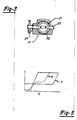
- Figure 3 is an enlarged cross-section view taken along the line 3-3 of Figure 2.
- Figure 4 is a family of curves showing the pressure at the exhaust port in connection with different constructions.
- Figure 5 is a graphical view showing how the reflective control valves may be operated.
- Referring now in detail to the drawings and particularly to Figures 1 and 2, a motorcycle powered by an internal combustion engine constructed in accordance with an embodiment of the invention is shown partially in phantom and is identified generally by the reference numeral 11. The motorcycle 11 includes a powering
internal combustion engine 12 which, in the illustrated embodiment, is depicted as being of the four cylinder, inline type. Theengine 12, in the illustrated embodiment, is of the four-cycle type, however, it is to be understood that the invention may be practiced with engines operating on the two-stroke cycle, and on engines having differing numbers of cylinders and different cylinder arrangements. Also, the invention is susceptible of use in other than reciprocating engines. However, the invention has utility in multi-cylinder engines of the type wherein there is a substantial overlap between the closing of the exhaust valve and the opening of the intake valve or, in the case of a two-cycle engine, the closing of the exhaust port and the opening of the intake port. - Since the invention deals with the exhaust system for the engine, the details of the engine have not been illustrated. It is to be understood, however, that the engine has an intake port and an exhaust port which are controlled either by valves, piston movement or the like, depending upon whether the engine is of the two or four-cycle type and that there is a substantial overlap between the opening of the intake valve and the closing of the exhaust valve as will be described.
- The
engine 12 is provided with an exhaust system, indicated generally by thereference numeral 13, and which is constructed in accordance with an embodiment of the invention. Theexhaust system 13 includes a plurality ofindividual exhaust pipes 14 that are flanged as at 15 at their inlet ends for cooperation with the cylinder head of theengine 12 so as to place theexhaust pipes 14 in communication at their inlet ends with the exhaust ports of theengine 12. At their outlet ends, theexhaust pipes 14 discharge into anexpansion chamber 16 through a valve assembly, indicated generally by thereference numeral 17 and constructed in accordance with an embodiment of the invention. The exhaust gases are delivered from theexpansion chamber 16 to the atmosphere through a pair of combined muffler andtailpipes 18 which lie on opposite sides of the rear wheel of the motorcycle. - Except for the
valve mechanism 17 and the way it is operated, which will be described, theengine 12 and itsexhaust system 13 may be considered to be conventional. Theengine 12 is designed to be of the high output type and has a substantial overlap in its valve timing. As a result, theengine 12, with itsexhaust system 13 and without considering the operation of thevalve mechanism 17, will produce a torque curve at high speeds that is extremely good and provides a high power. However, at the intermediate ranges, the torque curve falls off rather badly and these are the normal cruising speeds of the engine. Also, at the idle condition and low speed, the torque is also not good and poor running results. - This poor low and mid-range torque curve is a result of the fact that pressure pulses occur at the exhaust ports during the overlap period which pressure pulses tend to cause exhaust gases to flow back into the combustion chamber. As a result, the combustion chamber is not filled with a fresh fuel/air charge and these poor performance characteristics result. At high engine speeds, the positive pressure pulses do not occur at the exhaust port during the overlap and hence this phenomenon occurs at other than high speed conditions. The reason for this may be seen by looking at the top curve of Figure 4 wherein the pressure at the exhaust port of an engine operating at a low speed condition is identified by the curve a. During the period of valve operlap L, there is a positive pressure at the exhaust ports of the cylinders, which positive pressure occurs at least in part due to the transmission of pressure pulses from other exhaust ports back to any one exhaust port through the
expansion chamber 16. Hence, this positive pressure causes the deleterious effects as aforenoted. - In accordance with the invention, the
valve mechanism 17 is employed for preventing the existance of such positive pressures at the exhaust port during the overlap period and under predetermined running conditions. - Referring now specifically to Figures 2 and 3, the
valve assembly 17 includes a valve body 19 that has a plurality ofpassage 21 that cooperate with theexhaust pipe outlets 14 to deliver exhaust gases into theexpansion chamber 16. In each of thepassages 21, there is provided acontrol valve 22 for controlling the pressure at the exhaust ports of the engine. - The
control valves 22 are all affixed to a commoncontrol valve shaft 23 that is journaled in a suitable manner in the valve body 19. At one end of theshaft 23, there is provided acontrol pulley 24 around which is wound a flexible transmitter 25. The transmitter 25 is, in turn, operated by means of acontrol motor 26 that may be of any known type motor such as a vacuum motor, electric motor, electric solenoid or the like. Thecontrol motor 26 is, in turn, operated by means of alogic device 27 that controls the position of thevalves 22 in response to preset conditions. These preset conditions may be either engine speed, carburetor throttle valve position, boost pressure (in the event the engine is super-charged), engine load, or any other type of arrangement for providing the necessary control signal in response to the running condition. - In a preferred embodiment of the invention, the cross-sectonal area of the
reflective control valve 22 is such that when they are fully closed, as shown in Figure 3, that they will obstruct an area of the effective cross-sectional area of theexhaust pipes 14. The effective cross-sectional area which is obstructed when thevalves 22 are closed can be varied to change running conditions. Figure 4 shows two additional curves, one (curve b) in which thevalve 22 closes approximately 50% of the effective cross-sectional area while the other, curve c, shows an arrangement wherein thevalve 22 closes 90% of the effective area. These areas are generated at idle conditions which is approximately equal to 1,200 rpm in an embodiment of the invention. As can be seen, the greater the effective closing, the less the pressure peaks which occur during the overlap period L. Of course, those skilled in the art can determine the appropriate size of the restriction so as to suit particular running conditions. - Figure 5 is a view that shows how the
valves 22 are closed in response to an engine running condition. In the illustrated embodiment, the arrangement is such that thecontrol valves 22 are closed in response to the speed of the engine. Of course, as has been previously noted, other types of controls can be employed. In the solid line view shown in this figure, thevalves 22 are held closed from an idle position up to a low speed condition and then are opened progressively until they reach fully opened position at approximately half engine speed. However, it is to be understood that differing opening arrangements may be employed as shown by the dotted line curve d or the dot-dash curve a. Those skilled in the art can readily determine which type of arrangement best suits a given engine performance bearing in mind the number of cylinders, firing order, and so forth. However, in each instance, the arrangement is such that the torque of the engine can be significantly improved at low speed running. - It should be readily apparent from the foregoing description that an improved exhaust system has been provided for an internal combustion engine wherein the engine power output may be improved throughout the entire load and speed ranges without making any sacrifices or compromises. Although the invention has been illustrated in connection with a specific embodiment of the invention, as already noted, various changes and modifications may be made without departing from the spirit and scope of the invention, as defined by the appended claims.
Claims (7)
Priority Applications (3)
| Application Number | Priority Date | Filing Date | Title |
|---|---|---|---|
| DE3750981T DE3750981T2 (en) | 1987-02-11 | 1987-02-11 | High performance exhaust system for internal combustion engines. |
| ES87101882T ES2069524T3 (en) | 1987-02-11 | 1987-02-11 | HIGH PERFORMANCE EXHAUST SYSTEM FOR INTERNAL COMBUSTION ENGINE. |
| EP87101882A EP0278032B1 (en) | 1987-02-11 | 1987-02-11 | High performance exhaust system for internal combustion engine |
Applications Claiming Priority (1)
| Application Number | Priority Date | Filing Date | Title |
|---|---|---|---|
| EP87101882A EP0278032B1 (en) | 1987-02-11 | 1987-02-11 | High performance exhaust system for internal combustion engine |
Publications (2)
| Publication Number | Publication Date |
|---|---|
| EP0278032A1 true EP0278032A1 (en) | 1988-08-17 |
| EP0278032B1 EP0278032B1 (en) | 1995-01-11 |
Family
ID=8196745
Family Applications (1)
| Application Number | Title | Priority Date | Filing Date |
|---|---|---|---|
| EP87101882A Expired - Lifetime EP0278032B1 (en) | 1987-02-11 | 1987-02-11 | High performance exhaust system for internal combustion engine |
Country Status (3)
| Country | Link |
|---|---|
| EP (1) | EP0278032B1 (en) |
| DE (1) | DE3750981T2 (en) |
| ES (1) | ES2069524T3 (en) |
Cited By (3)
| Publication number | Priority date | Publication date | Assignee | Title |
|---|---|---|---|---|
| EP0479342A2 (en) * | 1986-09-13 | 1992-04-08 | Yamaha Motor Co., Ltd. | High performance exhaust system for internal combustion engine |
| CN1039846C (en) * | 1992-09-02 | 1998-09-16 | 本田技研工业株式会社 | Exhaust gas purifier for two-cycle engine |
| CN1076436C (en) * | 1998-01-21 | 2001-12-19 | 干方飞 | Exhaust muffler for internal combustion engine |
Citations (3)
| Publication number | Priority date | Publication date | Assignee | Title |
|---|---|---|---|---|
| US2717583A (en) * | 1951-11-09 | 1955-09-13 | Maybach | Control system for internal combustion engines |
| FR1132431A (en) * | 1955-05-24 | 1957-03-11 | Improvements to internal combustion engines | |
| US2862490A (en) * | 1954-10-20 | 1958-12-02 | Gen Motors Corp | Engine |
Family Cites Families (1)
| Publication number | Priority date | Publication date | Assignee | Title |
|---|---|---|---|---|
| JPH0819853B2 (en) * | 1986-09-13 | 1996-02-28 | ヤマハ発動機株式会社 | Engine exhaust control device |
-
1987
- 1987-02-11 DE DE3750981T patent/DE3750981T2/en not_active Expired - Fee Related
- 1987-02-11 ES ES87101882T patent/ES2069524T3/en not_active Expired - Lifetime
- 1987-02-11 EP EP87101882A patent/EP0278032B1/en not_active Expired - Lifetime
Patent Citations (3)
| Publication number | Priority date | Publication date | Assignee | Title |
|---|---|---|---|---|
| US2717583A (en) * | 1951-11-09 | 1955-09-13 | Maybach | Control system for internal combustion engines |
| US2862490A (en) * | 1954-10-20 | 1958-12-02 | Gen Motors Corp | Engine |
| FR1132431A (en) * | 1955-05-24 | 1957-03-11 | Improvements to internal combustion engines |
Non-Patent Citations (2)
| Title |
|---|
| PATENT ABSTRACTS OF JAPAN, vol. 11, no. 175 (M-596)[2622], 5th June 1987; & JP-A-62 007 924 (HONDA MOTOR CO. LTD) 14-01-1987 * |
| PATENT ABSTRACTS OF JAPAN, vol. 6, no. 267 (M-182)[1145], 25th December 1982; & JP-A-57 159 919 (HINO JIDOSHA KOGYO K.K.) 02-10-1982 * |
Cited By (4)
| Publication number | Priority date | Publication date | Assignee | Title |
|---|---|---|---|---|
| EP0479342A2 (en) * | 1986-09-13 | 1992-04-08 | Yamaha Motor Co., Ltd. | High performance exhaust system for internal combustion engine |
| EP0479342A3 (en) * | 1986-09-13 | 1992-07-08 | Yamaha Motor Co., Ltd. | High performance exhaust system for internal combustion engine |
| CN1039846C (en) * | 1992-09-02 | 1998-09-16 | 本田技研工业株式会社 | Exhaust gas purifier for two-cycle engine |
| CN1076436C (en) * | 1998-01-21 | 2001-12-19 | 干方飞 | Exhaust muffler for internal combustion engine |
Also Published As
| Publication number | Publication date |
|---|---|
| DE3750981T2 (en) | 1995-05-18 |
| DE3750981D1 (en) | 1995-02-23 |
| ES2069524T3 (en) | 1995-05-16 |
| EP0278032B1 (en) | 1995-01-11 |
Similar Documents
| Publication | Publication Date | Title |
|---|---|---|
| US4813232A (en) | Exhaust device for internal combustion engine | |
| US5063888A (en) | Exhaust control valve system for parallel multi-cylinder two-cycle engine | |
| US4630446A (en) | Outboard motor with turbo-charger | |
| US4617896A (en) | Internal combustion engine having three intake valves per cylinder | |
| US4702218A (en) | Engine intake system having a pressure wave supercharger | |
| US4566422A (en) | Fuel intake system for a supercharged engine | |
| JPH0217686B2 (en) | ||
| EP0413316A1 (en) | Exhaust control valve system for parallel multi-cylinder two-cycle engine | |
| US4998512A (en) | Exhaust port control system for two stroke engine | |
| US4986780A (en) | Two cycle engine | |
| US4528958A (en) | Intake control system of engine | |
| US5660155A (en) | Four-cycle engine | |
| US4422415A (en) | Intake system of engines | |
| US4909033A (en) | High performance exhaust system for internal combustion engine | |
| US4660530A (en) | Intake system for internal combustion engine | |
| US4912930A (en) | High performance exhaust system for internal combustion engine | |
| US4488519A (en) | Intake system for four-cycle engines | |
| JP3280758B2 (en) | Intake device for engine with mechanical supercharger | |
| EP0278032B1 (en) | High performance exhaust system for internal combustion engine | |
| EP0344780B1 (en) | Intake control device for engine | |
| EP0278033B1 (en) | High performance exhaust system for internal combustion engine | |
| JP3119925B2 (en) | Engine control device | |
| CA1281293C (en) | High performance exhaust system for internal combustion engine | |
| CA1281292C (en) | High performance exhaust system for internal combustion engine | |
| JP3377828B2 (en) | Intake device for engine with mechanical supercharger |
Legal Events
| Date | Code | Title | Description |
|---|---|---|---|
| PUAI | Public reference made under article 153(3) epc to a published international application that has entered the european phase |
Free format text: ORIGINAL CODE: 0009012 |
|
| AK | Designated contracting states |
Kind code of ref document: A1 Designated state(s): DE ES FR GB IT |
|
| 17P | Request for examination filed |
Effective date: 19890217 |
|
| 17Q | First examination report despatched |
Effective date: 19890626 |
|
| GRAA | (expected) grant |
Free format text: ORIGINAL CODE: 0009210 |
|
| AK | Designated contracting states |
Kind code of ref document: B1 Designated state(s): DE ES FR GB IT |
|
| REF | Corresponds to: |
Ref document number: 3750981 Country of ref document: DE Date of ref document: 19950223 |
|
| ITF | It: translation for a ep patent filed | ||
| ET | Fr: translation filed | ||
| REG | Reference to a national code |
Ref country code: ES Ref legal event code: FG2A Ref document number: 2069524 Country of ref document: ES Kind code of ref document: T3 |
|
| PLBE | No opposition filed within time limit |
Free format text: ORIGINAL CODE: 0009261 |
|
| STAA | Information on the status of an ep patent application or granted ep patent |
Free format text: STATUS: NO OPPOSITION FILED WITHIN TIME LIMIT |
|
| 26N | No opposition filed | ||
| REG | Reference to a national code |
Ref country code: GB Ref legal event code: IF02 |
|
| PGFP | Annual fee paid to national office [announced via postgrant information from national office to epo] |
Ref country code: FR Payment date: 20040210 Year of fee payment: 18 |
|
| PGFP | Annual fee paid to national office [announced via postgrant information from national office to epo] |
Ref country code: GB Payment date: 20040211 Year of fee payment: 18 |
|
| PGFP | Annual fee paid to national office [announced via postgrant information from national office to epo] |
Ref country code: DE Payment date: 20040219 Year of fee payment: 18 |
|
| PGFP | Annual fee paid to national office [announced via postgrant information from national office to epo] |
Ref country code: ES Payment date: 20040227 Year of fee payment: 18 |
|
| PG25 | Lapsed in a contracting state [announced via postgrant information from national office to epo] |
Ref country code: IT Free format text: LAPSE BECAUSE OF NON-PAYMENT OF DUE FEES Effective date: 20050211 Ref country code: GB Free format text: LAPSE BECAUSE OF NON-PAYMENT OF DUE FEES Effective date: 20050211 |
|
| PG25 | Lapsed in a contracting state [announced via postgrant information from national office to epo] |
Ref country code: ES Free format text: LAPSE BECAUSE OF NON-PAYMENT OF DUE FEES Effective date: 20050212 |
|
| PG25 | Lapsed in a contracting state [announced via postgrant information from national office to epo] |
Ref country code: DE Free format text: LAPSE BECAUSE OF NON-PAYMENT OF DUE FEES Effective date: 20050901 |
|
| GBPC | Gb: european patent ceased through non-payment of renewal fee |
Effective date: 20050211 |
|
| PG25 | Lapsed in a contracting state [announced via postgrant information from national office to epo] |
Ref country code: FR Free format text: LAPSE BECAUSE OF NON-PAYMENT OF DUE FEES Effective date: 20051031 |
|
| REG | Reference to a national code |
Ref country code: FR Ref legal event code: ST Effective date: 20051031 |
|
| REG | Reference to a national code |
Ref country code: ES Ref legal event code: FD2A Effective date: 20050212 |