EP0277971B1 - Self-scavenging gear box lubrication system - Google Patents
Self-scavenging gear box lubrication system Download PDFInfo
- Publication number
- EP0277971B1 EP0277971B1 EP87905067A EP87905067A EP0277971B1 EP 0277971 B1 EP0277971 B1 EP 0277971B1 EP 87905067 A EP87905067 A EP 87905067A EP 87905067 A EP87905067 A EP 87905067A EP 0277971 B1 EP0277971 B1 EP 0277971B1
- Authority
- EP
- European Patent Office
- Prior art keywords
- gear
- chamber
- gear chamber
- cavity
- fluid
- Prior art date
- Legal status (The legal status is an assumption and is not a legal conclusion. Google has not performed a legal analysis and makes no representation as to the accuracy of the status listed.)
- Expired - Lifetime
Links
- 238000005461 lubrication Methods 0.000 title claims abstract description 24
- 239000012530 fluid Substances 0.000 claims abstract description 39
- 230000001050 lubricating effect Effects 0.000 claims abstract description 20
- 230000002000 scavenging effect Effects 0.000 claims description 9
- 238000001816 cooling Methods 0.000 abstract description 3
- 230000005540 biological transmission Effects 0.000 description 30
- 239000000314 lubricant Substances 0.000 description 10
- 239000007788 liquid Substances 0.000 description 4
- 239000002826 coolant Substances 0.000 description 3
- 239000013585 weight reducing agent Substances 0.000 description 2
- 239000002131 composite material Substances 0.000 description 1
- 238000010276 construction Methods 0.000 description 1
- 239000012809 cooling fluid Substances 0.000 description 1
- 239000005068 cooling lubricant Substances 0.000 description 1
- 238000010586 diagram Methods 0.000 description 1
- 230000000694 effects Effects 0.000 description 1
- 235000003642 hunger Nutrition 0.000 description 1
- 239000000463 material Substances 0.000 description 1
- 230000003134 recirculating effect Effects 0.000 description 1
- 239000007787 solid Substances 0.000 description 1
- 230000003068 static effect Effects 0.000 description 1
Images




Classifications
-
- F—MECHANICAL ENGINEERING; LIGHTING; HEATING; WEAPONS; BLASTING
- F16—ENGINEERING ELEMENTS AND UNITS; GENERAL MEASURES FOR PRODUCING AND MAINTAINING EFFECTIVE FUNCTIONING OF MACHINES OR INSTALLATIONS; THERMAL INSULATION IN GENERAL
- F16H—GEARING
- F16H57/00—General details of gearing
- F16H57/04—Features relating to lubrication or cooling or heating
- F16H57/048—Type of gearings to be lubricated, cooled or heated
- F16H57/0493—Gearings with spur or bevel gears
-
- F—MECHANICAL ENGINEERING; LIGHTING; HEATING; WEAPONS; BLASTING
- F16—ENGINEERING ELEMENTS AND UNITS; GENERAL MEASURES FOR PRODUCING AND MAINTAINING EFFECTIVE FUNCTIONING OF MACHINES OR INSTALLATIONS; THERMAL INSULATION IN GENERAL
- F16H—GEARING
- F16H57/00—General details of gearing
- F16H57/04—Features relating to lubrication or cooling or heating
- F16H57/0402—Cleaning of lubricants, e.g. filters or magnets
-
- F—MECHANICAL ENGINEERING; LIGHTING; HEATING; WEAPONS; BLASTING
- F16—ENGINEERING ELEMENTS AND UNITS; GENERAL MEASURES FOR PRODUCING AND MAINTAINING EFFECTIVE FUNCTIONING OF MACHINES OR INSTALLATIONS; THERMAL INSULATION IN GENERAL
- F16H—GEARING
- F16H57/00—General details of gearing
- F16H57/04—Features relating to lubrication or cooling or heating
- F16H57/0412—Cooling or heating; Control of temperature
- F16H57/0415—Air cooling or ventilation; Heat exchangers; Thermal insulations
-
- F—MECHANICAL ENGINEERING; LIGHTING; HEATING; WEAPONS; BLASTING
- F16—ENGINEERING ELEMENTS AND UNITS; GENERAL MEASURES FOR PRODUCING AND MAINTAINING EFFECTIVE FUNCTIONING OF MACHINES OR INSTALLATIONS; THERMAL INSULATION IN GENERAL
- F16N—LUBRICATING
- F16N7/00—Arrangements for supplying oil or unspecified lubricant from a stationary reservoir or the equivalent in or on the machine or member to be lubricated
- F16N7/38—Arrangements for supplying oil or unspecified lubricant from a stationary reservoir or the equivalent in or on the machine or member to be lubricated with a separate pump; Central lubrication systems
- F16N7/40—Arrangements for supplying oil or unspecified lubricant from a stationary reservoir or the equivalent in or on the machine or member to be lubricated with a separate pump; Central lubrication systems in a closed circulation system
-
- F—MECHANICAL ENGINEERING; LIGHTING; HEATING; WEAPONS; BLASTING
- F16—ENGINEERING ELEMENTS AND UNITS; GENERAL MEASURES FOR PRODUCING AND MAINTAINING EFFECTIVE FUNCTIONING OF MACHINES OR INSTALLATIONS; THERMAL INSULATION IN GENERAL
- F16H—GEARING
- F16H57/00—General details of gearing
- F16H57/04—Features relating to lubrication or cooling or heating
- F16H57/042—Guidance of lubricant
- F16H57/0421—Guidance of lubricant on or within the casing, e.g. shields or baffles for collecting lubricant, tubes, pipes, grooves, channels or the like
- F16H57/0423—Lubricant guiding means mounted or supported on the casing, e.g. shields or baffles for collecting lubricant, tubes or pipes
-
- Y—GENERAL TAGGING OF NEW TECHNOLOGICAL DEVELOPMENTS; GENERAL TAGGING OF CROSS-SECTIONAL TECHNOLOGIES SPANNING OVER SEVERAL SECTIONS OF THE IPC; TECHNICAL SUBJECTS COVERED BY FORMER USPC CROSS-REFERENCE ART COLLECTIONS [XRACs] AND DIGESTS
- Y10—TECHNICAL SUBJECTS COVERED BY FORMER USPC
- Y10T—TECHNICAL SUBJECTS COVERED BY FORMER US CLASSIFICATION
- Y10T74/00—Machine element or mechanism
- Y10T74/19—Gearing
- Y10T74/19991—Lubrication
Definitions
- This invention relates to lubricating systems and particularly to a gear box lubricating system which is self-scavenging.
- the lubrication system must provide a continual supply of lubricant to the moving surfaces, such as the meshing gears, and must perform a cooling effect.
- the lubricant is scavenged from the housing or gear box of the power transmission system or gear train and recirculated through a sump to appropriate recirculating pump means.
- the recirculation circuit may or may not include a filter and the cooling lubricant is returned to the gear box to provide a continuous supply of a cooling medium.
- a typical one of such transmissions includes a rotary input element and a rotary output element.
- gear trains individually connect the input element and the output element. Therefore, the energy or power being transmitted from the input to the output is nominally divided by the number of gear trains interconnecting the two.
- Typical advantages flowing from such a construction include the ability to use gears of a lesser face width than would otherwise be required, the use of smaller bearings, the use of lesser material with commensurate weight reduction, and the like.
- multiple path transmissions frequently are less noisy during operation than single path transmissions.
- An example of the use of such multiple load path power transmissions is disclosed herein in conjunction with a turbine for a torpedo or the like.
- EP 0166658 describes a gear box lubrication system as defined in the first part of claim 1 including a housing, a gear chamber in the housing and meshing gears in the gear chamber.
- a passage extends from the gear chamber, tangentially to one of the gears, towards a reservoir.
- Lubricating fluid circulating in the gear chamber may be expelled under centrifugal action through the passageway, which includes a section of restricted diameter.
- a return circuit for expelled fluid from the reservoir to the gear chamber is provided. There is only one tangential passageway and one reservoir, and there is no scavenging pump.
- An object, therefore, of the invention is to provide a new and improved lubricant scavenging system and, particularly, to a self-scavenging lubrication system for power transmissions, gear trains or the like.
- the self-scavenging lubrication system is illustrated as embodied in the gear box of a multiple load path power transmission.
- a gear box housing has a gear chamber providing relatively close conformation with meshing gears rotatably mounted in the chamber.
- Means are provided for delivering lubricating fluid to the chamber from an appropriate lubrication supply network.
- a plurality of lubricating fluid collecting cavities is provided in the housing separate from the gear chamber. Passage means communicate between the gear chamber and each collecting cavity for passing fluid from the chamber to the cavity under the influence of centrifugal action effected by rotation of the gears whereby the fluid can be scavenged from the cavities by appropriate lubrication pump means.
- the passage means are oriented generally tangentially of the meshing gears.
- the passage means are of restricted dimensions to provide a positive inlet pressure to prevent backflow from the collecting cavities into the gear chamber at all attitudes.
- the restricted passage means creates a velocity head which is converted to a pressure head to prevent backflow.
- Stripper means are provided at the entrance to each passage means from the gear chamber for directing the lubricating fluid from the chamber into the passage means as the fluid is forced outwardly under the centrifugal action of the rotating gears.
- the cavities are disposed angularly around the gear chamber, preferably so as to substantially surround it. There is desirably at least one cavity on each opposite side of the gear chamber.
- Fluid conduit means suitably communicate between the collecting cavities.
- the conduit means include a plurality of conduits to prevent one cavity from becoming dry relative to another cavity.
- the conduits all lead to a single cavity from which the fluid or lubricating coolant can be scavenged by appropriate pump means to supply the lubrication circuit.
- FIG. 1 An exemplary embodiment of a power transmission, particularly a multiple load path transmission, embodying the self-scavenging gear box lubrication system of the invention is illustrated in Figure 1 in connection with a turbine wheel 10.
- the turbine wheel is part of a turbine drive for an underwater propulsion system, such as a torpedo.
- Turbine wheel 10 drives an input shaft shown in phantom, as at 12.
- First and second gear trains, generally designated 16 and 18, are generally identical in configuration and connect an input gear 14 and a relatively large output gear 20 which drives an output shaft 22.
- each of the gear trains 16 and 18 includes a first reduction stage comprised of a relatively large gear 24 (only one visible in Fig. 1) meshed with input gear 14.
- Gears 24 are rotatable about axes defined by associated shafts 26.
- first relatively small gears 28 in each gear train 16 and 18 which serve as part of second reduction stages.
- Second shafts 30, which are parallel to shafts 12,22 and 26, journal force equalizing gears 32 of relatively large size and which are meshed with corresponding ones of the small gears 28.
- Journalled for rotation about the axis defined by the shafts 30 in unison with gears 32 are relatively small gears 34 which are meshed with output gear 20, which it will be recalled, is relatively large.
- gears 34 and gear 20 define the third reduction stages.
- Turbine wheel 10 is seen to be an axial flow turbine receiving a pressurized fluid from a manifold 38.
- the pressurized fluid may be, for example, steam, when the turbine forms part of an underwater propulsion system such as a torpedo.
- the fluid passing through turbine wheel 10 is directed by an exhaust baffle 40 through a heat exchanger 42 comprised of a plurality of tubes which may be utilized as a regenerator in a closed cycle system. From regenerator 42, the steam is passed through an outlet 44 to a condenser or the like.
- the turbine wheel shaft 12 is journalled by bearings 46 within the housing components.
- a lubricant or cooling fluid is continuously supplied to the transmission described above and will flow around, through and/or between the various gears, shafts, bearings or the like described above. For instance, some of these areas are defined by the spaces, channels or the like identified by the numerals 48a through 48i in Figure 1.
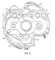
- the lubricant supply conduit means is not visible in Figure 1. However, a filter 50 is illustrated in a compartment 52 within housing 54 and which is part of the lubrication network or circuit, as described hereinafter.
- Figure 1 does show portions of a plurality of collecting cavities 56, 58 and 60 in a gear box housing means generally designated 54 and including housing portions 54A, 548 and 54C. Plates 55A and 55B are disposed between the housing portions as seen in Figure 1. Suffice it to say at this point, the scavenged lubricant eventually is channelled to collecting cavity 60 whereupon it is scavenged by appropriate lubrication pump means to supply the circuit described hereinafter.
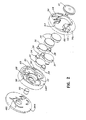
- FIG 2 shows an exploded perspective view of housing portions 54A-54C in relation to turbine 10 and the triple speed reduction gear train or transmission described above in relation to Figure 1, including gears 20, 24, 28, 32 and 34.
- the location of collecting cavities 58 and 60 in housing portion 548 also is illustrated. It can be seen that these cavities 58 and 60 generally are located above and below, respectively, the transmission area, which also is illustrated in Figure 1.
- a fourth collecting cavity 62 is located in housing portion 54C on the side thereof opposite collecting cavity 56. Cavities 56, 62 can be seen to be located generally on opposite sides of the transmission area. Therefore, collecting cavities 56, 58, 60 and 62 substantially surround the transmission area defined by the enumerated gears.
- the gears are located in closely conforming gear chambers 63 in housing portion 54C and 65 in housing portion 54B. In essence, these gear chambers in the two housing portions form a composite gear chamber for the transmission.
- Figure 3 is a somewhat unusual drawing which is being used to better illustrate the relationship of the transmission gears and the collecting cavities.
- the gears are shown somewhat schematically as solid circular bodies with the reference numerals 20, 24, 28, 32 and 34 applied thereto as described in relation to Figures 1 and 2.
- cavities 56, 58, 60 and 62 are shown as enclosed compartments when, in fact, as described in relation to Figures 1 and 2, the cavities are spaces formed within housing portions 54B and 54C. This depiction of the cavities in Figure 3 is being used to facilitate a better understanding of the operation of the invention.
- passage means are provided between the gear chambers 63 and 65 and the collecting cavities 56-62 for passing the lubricating fluid from the respective gear chambers to the respective collecting cavities under the influence of centrifugal action effected by rotation of the gears in the respective gear chambers whereby the fluid can be scavenged therefrom.
- a passage 64 is provided in housing portion 54C for directing fluid from lower gear 24 into collecting chamber 56.
- a passage 66 is provided in housing portion 54C for directing fluid from upper gear 24 into collecting chamber 62.
- a passage 68 is provided in housing portion 54B for delivering fluid from gear 20 to collecting cavity 58.
- a passage 70 is provided in housing portion 54B for delivering fluid from the rear gear 32 (as viewed in Figs. 2 and 3) to collecting chamber 60.
- an enlarged portion 72 of gear chamber 65 (Fig. 2) directs fluid onto rear gear 32, as at 74 in Figure 3, which, in turn, directs the fluid through passage 70 into collecting chamber 60 as described above.
- each of passages 64-74 are oriented tangentially of the respective meshing gears and are located at the peripheries of the gear chamber. Therefore, the fluid is directed to the respective collecting cavities under the influence of centrifugal action effected by rotation of the respective gears without any accessory pump means or other apparatus.
- passages 64-74 have restricted dimensions such that the coolant or lubricant cannot flow back into the respective gear chambers when the gears rotate. Not only is backflow prevented, but a positive pressure is created whereby the system is attitude insensitive. In other words, the dynamic head created by the centrifugal force of the liquid into and through the passages is greater than the static head of liquid within the gear box. The velocity of the liquid passing through the passages, in essence, is converted to a pressure or dynamic head.
- stripper means are provided at the entrance of the passages for facilitating directing the lubricating fluid from the gear chamber into the respective passage.
- Figure 3 also shows conduit means interconnecting collecting cavities 56, 58, 60 and 62 whereby the lubricating fluid directed thereinto under the centrifugal action of the gears is channelled to a single collecting chamber, namely collecting chamber 60, for scavenging therefrom by appropriate lubrication pump means. More particularly, Figure 3 shows the conduit means in the form of conduits 76, 78 80a, 80b, and 82a, 82b. It can be seen that conduits 76 and 78 interconnect the tops of collecting cavities 56, 62 with collecting cavity 58 generally at the top thereof. Conduits 80a and 82a interconnect the bottom of collecting cavity 58 with center collecting cavity 60.
- Conduits 80b and 82b interconnect the bottoms of collecting cavities 56 and 62, respectively, with collecting cavity 60. Therefore, it can be seen that all of the collecting cavities are interconnected with a single collecting cavity, namely collecting cavity 60.
- the lubricating fluid is scavenged from collecting cavity 60 through a lubrication pump outlet schematically shown at 84 which leads to an appropriate lubrication pump means.
- Figure 3 shows conduits 76, 78, 80a, 80b, 82a and 82b as elongated tubes when, in fact, the conduits simply comprise apertures or holes in plates 55A and 55B (Fig. 1) between housing portions 54A, 54B and 54C, and as will be seen somewhat in Figures 4 and 5.
- the conduits are shown as tubes in Figure 3 simply to facilitate a schematic illustration of the interconnection between the collecting cavities in an exploded perspective view. It also can be seen in Figure 3 that conduits 76-82b are spaced angularly about the gear transmission area and about the gear chamber. This arrangement is provided so that no single one collecting chamber can become "dry".
- the conduits interconnect the collecting cavities at upper, lower and side locations to prevent such starving or choking of the system.
- Figure 4 shows an elevational view of the lefthand side of housing portion 54C as viewed in Figure 1.
- the relative locations of collecting cavities 56 and 62 can be seen in relation to gear chamber 63. It also can be seen how passages 64 and 66 are oriented tangentially of the gear chamber (and the meshing gears), as well as their restricted dimensions to prevent backflow.
- stripper means are provided at the entrances to the passages from the respective gear chambers for facilitating directing the lubricating fluid from the chambers into the passages under centrifugal action.
- This stripper means is shown at 86 defining the entrance to passage 64 and at 88 defining the entrance to passage 66. Lastly, the interconnecting conduits 76, 78, 80b and 82b are shown by dotted lines.
- Figure 5 shows an elevational view of the righthand side of housing portion 54B as viewed in Figure 1.
- the relative positioning of collecting cavities 58 and 60 with respect to gear chamber 65 can be seen best in this view.
- passages 68 and 70 extend tangentially of the gear chamber at their respective locations, as well as the restricted dimensions of the passages.
- stripper means 90 is provided at the entrance to passage 68.
- Stripper means 92 is provided for passage 70.
- the location of interconnecting conduits 58, 78, 80a and 82a also can be seen.
- a self scavenging gear box lubrication system has been provided without requiring multiple scavenging pumps as is prevalent with the prior art.
- the collecting cavities are self-contained within the transmission housing and are fed under the influence of centrifugal action effected by rotation of the gears.
- the manner in which the collecting cavities are interconnected prevent any single cavity from becoming "dry"; the system is attitude insensitive; and the lubricating fluid can be scavenged from a single collecting cavity.
- Figure 6 shows a simple lubrication circuit including a pump means 100 for scavenging the lubricating fluid from collecting cavity 60, as well as the interconnection between all of the collecting cavities 56-62.
Landscapes
- Engineering & Computer Science (AREA)
- General Engineering & Computer Science (AREA)
- Mechanical Engineering (AREA)
- General Details Of Gearings (AREA)
Abstract
Description
- This invention relates to lubricating systems and particularly to a gear box lubricating system which is self-scavenging.
- In many power transmission systems, such as gear train systems, continued lubrication is essential to proper operation. The lubrication system must provide a continual supply of lubricant to the moving surfaces, such as the meshing gears, and must perform a cooling effect.
- Conventionally, the lubricant is scavenged from the housing or gear box of the power transmission system or gear train and recirculated through a sump to appropriate recirculating pump means. The recirculation circuit may or may not include a filter and the cooling lubricant is returned to the gear box to provide a continuous supply of a cooling medium.
- In order to scavenge the lubricant from the gear box, separate scavenge pumps often are employed. In simple power transmissions or gear train systems, separate scavenge pumps have proven quite adequate. However, in more complicated power transmission systems, multiple scavenge pumps must be used to adequately perform the cooling function. When simplicity and weight are important design factors, multiple scavenge, pumps have proven either inadequate or undesirable.
- For instance, multiple load path transmissions have long been favoured for any of a variety of reasons. A typical one of such transmissions includes a rotary input element and a rotary output element. Typically, two or more, substantially identical, gear trains individually connect the input element and the output element. Therefore, the energy or power being transmitted from the input to the output is nominally divided by the number of gear trains interconnecting the two.
- Typical advantages flowing from such a construction include the ability to use gears of a lesser face width than would otherwise be required, the use of smaller bearings, the use of lesser material with commensurate weight reduction, and the like. In addition, multiple path transmissions frequently are less noisy during operation than single path transmissions. An example of the use of such multiple load path power transmissions is disclosed herein in conjunction with a turbine for a torpedo or the like.
- However, the advantages that may be obtained through the use of a multiple load path transmission are not unaccompanied by disadvantages. One such disadvantage is the circuitous surface areas of such a transmission system which must be continuously lubricated for proper operation. Scavenging the lubricant from such a system, such as the gear box of a multiple load path transmission, can become complicated. Where the multiple load path transmission is used primarily or in part for weight reduction reasons, multiple scavenging pumps defeats the very design parameters for using such a transmission system in the first place. Further problems with such transmission systems are caused in applications where the apparatus itself may attain various attitudes.
- EP 0166658 describes a gear box lubrication system as defined in the first part of claim 1 including a housing, a gear chamber in the housing and meshing gears in the gear chamber. A passage extends from the gear chamber, tangentially to one of the gears, towards a reservoir. Lubricating fluid circulating in the gear chamber may be expelled under centrifugal action through the passageway, which includes a section of restricted diameter. A return circuit for expelled fluid from the reservoir to the gear chamber is provided. There is only one tangential passageway and one reservoir, and there is no scavenging pump.
- An object, therefore, of the invention is to provide a new and improved lubricant scavenging system and, particularly, to a self-scavenging lubrication system for power transmissions, gear trains or the like.
- In the exemplary embodiment of the invention as defined in claim 1, the self-scavenging lubrication system is illustrated as embodied in the gear box of a multiple load path power transmission. A gear box housing has a gear chamber providing relatively close conformation with meshing gears rotatably mounted in the chamber. Means are provided for delivering lubricating fluid to the chamber from an appropriate lubrication supply network. A plurality of lubricating fluid collecting cavities is provided in the housing separate from the gear chamber. Passage means communicate between the gear chamber and each collecting cavity for passing fluid from the chamber to the cavity under the influence of centrifugal action effected by rotation of the gears whereby the fluid can be scavenged from the cavities by appropriate lubrication pump means.
- As disclosed herein, the passage means are oriented generally tangentially of the meshing gears. The passage means are of restricted dimensions to provide a positive inlet pressure to prevent backflow from the collecting cavities into the gear chamber at all attitudes.
- In essence, the restricted passage means creates a velocity head which is converted to a pressure head to prevent backflow. Stripper means are provided at the entrance to each passage means from the gear chamber for directing the lubricating fluid from the chamber into the passage means as the fluid is forced outwardly under the centrifugal action of the rotating gears.
- The cavities are disposed angularly around the gear chamber, preferably so as to substantially surround it. There is desirably at least one cavity on each opposite side of the gear chamber. Fluid conduit means suitably communicate between the collecting cavities. In the exemplary embodiment of the invention, the conduit means include a plurality of conduits to prevent one cavity from becoming dry relative to another cavity. Preferably. the conduits all lead to a single cavity from which the fluid or lubricating coolant can be scavenged by appropriate pump means to supply the lubrication circuit.
- The invention is illustrated by the drawings, in which like reference numerals identify like elements in the figures and in which:
- FIGURE 1 is a sectional view of a multiple load path transmission in connection with a turbine drive of the sort that may be utilized in an underwater propulsion system, and incorporating the self-scavenging lubrication system of the invention;
- FIGURE 2 is an exploded, perspective view of the gear train components and certain housing portions defining the scavenge cavities;
- FIGURE 3 is a somewhat schematic, exploded perspective view depicting the various gears, scavenge cavities, passage means and conduit means in accordance with the concepts of the invention;
- FIGURE 4 is an enlarged view taken generally in the direction of line 4-4 of Figure 1;
- FIGURE 5 is an enlarged view taken generally in the direction of line 5-5 of Figure 1; and
- FIGURE 6 is a schematic diagram of a simple lubrication circuit for use with the invention.
- An exemplary embodiment of a power transmission, particularly a multiple load path transmission, embodying the self-scavenging gear box lubrication system of the invention is illustrated in Figure 1 in connection with a
turbine wheel 10. The turbine wheel is part of a turbine drive for an underwater propulsion system, such as a torpedo.Turbine wheel 10 drives an input shaft shown in phantom, as at 12. First and second gear trains, generally designated 16 and 18, are generally identical in configuration and connect aninput gear 14 and a relativelylarge output gear 20 which drives anoutput shaft 22. - In the embodiment illustrated, the transmission provides for a triple speed reduction. Thus, each of the
gear trains input gear 14.Gears 24 are rotatable about axes defined by associatedshafts 26. Also journalled onshafts 26 are first relativelysmall gears 28 in eachgear train Second shafts 30, which are parallel toshafts gears 32 of relatively large size and which are meshed with corresponding ones of thesmall gears 28. Journalled for rotation about the axis defined by theshafts 30 in unison withgears 32 are relativelysmall gears 34 which are meshed withoutput gear 20, which it will be recalled, is relatively large. Thus,gears 34 andgear 20 define the third reduction stages. -
Turbine wheel 10 is seen to be an axial flow turbine receiving a pressurized fluid from amanifold 38. The pressurized fluid may be, for example, steam, when the turbine forms part of an underwater propulsion system such as a torpedo. The fluid passing throughturbine wheel 10 is directed by anexhaust baffle 40 through aheat exchanger 42 comprised of a plurality of tubes which may be utilized as a regenerator in a closed cycle system. Fromregenerator 42, the steam is passed through anoutlet 44 to a condenser or the like. Theturbine wheel shaft 12 is journalled bybearings 46 within the housing components. - A lubricant or cooling fluid is continuously supplied to the transmission described above and will flow around, through and/or between the various gears, shafts, bearings or the like described above. For instance, some of these areas are defined by the spaces, channels or the like identified by the numerals 48a through 48i in Figure 1. The lubricant supply conduit means is not visible in Figure 1. However, a
filter 50 is illustrated in acompartment 52 withinhousing 54 and which is part of the lubrication network or circuit, as described hereinafter. - The self-scavenging lubrication system of the invention is best illustrated in Figures 2-5. However, Figure 1 does show portions of a plurality of collecting
cavities housing portions Plates 55A and 55B are disposed between the housing portions as seen in Figure 1. Suffice it to say at this point, the scavenged lubricant eventually is channelled to collectingcavity 60 whereupon it is scavenged by appropriate lubrication pump means to supply the circuit described hereinafter. - Figure 2 shows an exploded perspective view of
housing portions 54A-54C in relation toturbine 10 and the triple speed reduction gear train or transmission described above in relation to Figure 1, includinggears cavities housing portion 548 also is illustrated. It can be seen that thesecavities cavity 62 is located in housing portion 54C on the side thereof opposite collectingcavity 56.Cavities cavities gear chambers 63 inhousing portion 54C and 65 in housing portion 54B. In essence, these gear chambers in the two housing portions form a composite gear chamber for the transmission. - Figure 3 is a somewhat unusual drawing which is being used to better illustrate the relationship of the transmission gears and the collecting cavities. Specifically, the gears are shown somewhat schematically as solid circular bodies with the
reference numerals cavities gear chambers - Specifically referring to both Figures 2 and 3, a
passage 64 is provided in housing portion 54C for directing fluid fromlower gear 24 into collectingchamber 56. Apassage 66 is provided in housing portion 54C for directing fluid fromupper gear 24 into collectingchamber 62. Apassage 68 is provided in housing portion 54B for delivering fluid fromgear 20 to collectingcavity 58. Apassage 70 is provided in housing portion 54B for delivering fluid from the rear gear 32 (as viewed in Figs. 2 and 3) to collectingchamber 60. There is no separate passage forfront gear 32 communicating with collectingcavity 60. Instead, anenlarged portion 72 of gear chamber 65 (Fig. 2) directs fluid ontorear gear 32, as at 74 in Figure 3, which, in turn, directs the fluid throughpassage 70 into collectingchamber 60 as described above. - It can be seen in Figures 2 and 3 that each of passages 64-74 are oriented tangentially of the respective meshing gears and are located at the peripheries of the gear chamber. Therefore, the fluid is directed to the respective collecting cavities under the influence of centrifugal action effected by rotation of the respective gears without any accessory pump means or other apparatus.
- It also can be seen in Figures 2 and 3 that passages 64-74 have restricted dimensions such that the coolant or lubricant cannot flow back into the respective gear chambers when the gears rotate. Not only is backflow prevented, but a positive pressure is created whereby the system is attitude insensitive. In other words, the dynamic head created by the centrifugal force of the liquid into and through the passages is greater than the static head of liquid within the gear box. The velocity of the liquid passing through the passages, in essence, is converted to a pressure or dynamic head. Lastly, as seen best in Figures 4 and 5, and as described hereinafter, stripper means are provided at the entrance of the passages for facilitating directing the lubricating fluid from the gear chamber into the respective passage.
- Figure 3 also shows conduit means interconnecting collecting
cavities chamber 60, for scavenging therefrom by appropriate lubrication pump means. More particularly, Figure 3 shows the conduit means in the form ofconduits conduits cavities cavity 58 generally at the top thereof.Conduits 80a and 82a interconnect the bottom of collectingcavity 58 withcenter collecting cavity 60.Conduits cavities cavity 60. Therefore, it can be seen that all of the collecting cavities are interconnected with a single collecting cavity, namely collectingcavity 60. The lubricating fluid is scavenged from collectingcavity 60 through a lubrication pump outlet schematically shown at 84 which leads to an appropriate lubrication pump means. - It is important to understand that Figure 3 shows
conduits plates 55A and 55B (Fig. 1) betweenhousing portions 54A, 54B and 54C, and as will be seen somewhat in Figures 4 and 5. The conduits are shown as tubes in Figure 3 simply to facilitate a schematic illustration of the interconnection between the collecting cavities in an exploded perspective view. It also can be seen in Figure 3 that conduits 76-82b are spaced angularly about the gear transmission area and about the gear chamber. This arrangement is provided so that no single one collecting chamber can become "dry". As is known, a pump will draw less viscous or less dense air from a dry chamber when interconnected with a chamber that contains liquid such as a lubricant, because of the obvious difference in resistance. Therefore, with the invention, the conduits interconnect the collecting cavities at upper, lower and side locations to prevent such starving or choking of the system. - Figure 4 shows an elevational view of the lefthand side of housing portion 54C as viewed in Figure 1. The relative locations of collecting
cavities chamber 63. It also can be seen howpassages - This stripper means is shown at 86 defining the entrance to
passage 64 and at 88 defining the entrance topassage 66. Lastly, the interconnectingconduits - Figure 5 shows an elevational view of the righthand side of housing portion 54B as viewed in Figure 1. The relative positioning of collecting
cavities chamber 65 can be seen best in this view. It also can be seen howpassages passage 68. Stripper means 92 is provided forpassage 70. The location of interconnectingconduits - From the foregoing, it can be seen that a self scavenging gear box lubrication system has been provided without requiring multiple scavenging pumps as is prevalent with the prior art. The collecting cavities are self-contained within the transmission housing and are fed under the influence of centrifugal action effected by rotation of the gears. The manner in which the collecting cavities are interconnected prevent any single cavity from becoming "dry"; the system is attitude insensitive; and the lubricating fluid can be scavenged from a single collecting cavity.
- Lastly, Figure 6 shows a simple lubrication circuit including a pump means 100 for scavenging the lubricating fluid from collecting
cavity 60, as well as the interconnection between all of the collecting cavities 56-62.
Claims (7)
Applications Claiming Priority (2)
| Application Number | Priority Date | Filing Date | Title |
|---|---|---|---|
| US06/886,346 US4715244A (en) | 1986-07-17 | 1986-07-17 | Self-scavenging gear box lubrication system |
| US886346 | 1986-07-17 |
Publications (3)
| Publication Number | Publication Date |
|---|---|
| EP0277971A4 EP0277971A4 (en) | 1988-07-14 |
| EP0277971A1 EP0277971A1 (en) | 1988-08-17 |
| EP0277971B1 true EP0277971B1 (en) | 1991-01-02 |
Family
ID=25388897
Family Applications (1)
| Application Number | Title | Priority Date | Filing Date |
|---|---|---|---|
| EP87905067A Expired - Lifetime EP0277971B1 (en) | 1986-07-17 | 1987-07-15 | Self-scavenging gear box lubrication system |
Country Status (4)
| Country | Link |
|---|---|
| US (1) | US4715244A (en) |
| EP (1) | EP0277971B1 (en) |
| JP (1) | JPH01500289A (en) |
| WO (1) | WO1988000665A1 (en) |
Families Citing this family (16)
| Publication number | Priority date | Publication date | Assignee | Title |
|---|---|---|---|---|
| JPH063255B2 (en) * | 1987-03-04 | 1994-01-12 | トヨタ自動車株式会社 | Automatic transmission transaxle case |
| US5425706A (en) * | 1989-02-24 | 1995-06-20 | S. I. Scientific Innovations Ltd. | Dispensing device particularly useful for dispensing nutritional liquids |
| US4953663A (en) * | 1989-03-17 | 1990-09-04 | Sundstrand Corporation | Oil supply for integrated drive generator |
| US5411116A (en) * | 1994-06-22 | 1995-05-02 | United Technologies Corporation | Self-scavenging, hybrid lubrication subsystem |
| DE10161374A1 (en) * | 2001-12-14 | 2003-06-26 | Opel Adam Ag | Lubricant supply for a planetary gear |
| ITAN20030028A1 (en) * | 2003-05-16 | 2004-11-17 | Rodolfo Panatta | GYM BIKE THAT USES THE EFFECT OF |
| DE102006005354A1 (en) * | 2006-02-07 | 2007-08-09 | Deere & Company, Moline | transmission assembly |
| US8192143B2 (en) | 2008-05-21 | 2012-06-05 | United Technologies Corporation | Gearbox assembly |
| US9470303B2 (en) | 2013-10-08 | 2016-10-18 | Sikorsky Aircraft Corporation | Self scavenging gear shield |
| DE102014119074A1 (en) * | 2014-12-18 | 2016-06-23 | Rolls-Royce Deutschland Ltd & Co Kg | Oil circuit of an aircraft engine |
| US9759094B2 (en) | 2015-06-24 | 2017-09-12 | General Electric Company | Pump for a turbine engine |
| US10428928B2 (en) | 2017-03-24 | 2019-10-01 | Hamilton Sundstrand Corporation | Lubrication system for high speed gearbox operating in zero gravity |
| US20190285163A1 (en) * | 2018-03-15 | 2019-09-19 | GM Global Technology Operations LLC | Vehicle propulsion system |
| US11162494B2 (en) | 2019-01-23 | 2021-11-02 | Pratt & Whitney Canada Corp. | Scavenge pump |
| DE102021201491A1 (en) | 2021-02-17 | 2022-08-18 | Zf Friedrichshafen Ag | Oil system for a gearbox, gearbox with the oil system and aircraft with the oil system and/or the gearbox |
| JP7632428B2 (en) * | 2022-10-07 | 2025-02-19 | トヨタ自動車株式会社 | Power transmission |
Family Cites Families (23)
| Publication number | Priority date | Publication date | Assignee | Title |
|---|---|---|---|---|
| US1220810A (en) * | 1915-09-01 | 1917-03-27 | Gen Electric | Spur-gearing. |
| US1357301A (en) * | 1918-08-07 | 1920-11-02 | Reaugh Frank | Oiling system |
| US1610886A (en) * | 1923-05-28 | 1926-12-14 | Gen Electric | Lubricating arrangement for gearing |
| FR854747A (en) * | 1938-05-30 | 1940-04-23 | Zahnradfabrik Friedrichshafen | Gearbox for motor vehicles |
| US2235793A (en) * | 1938-09-21 | 1941-03-18 | Master Electric Co | Lubricating apparatus |
| US2386367A (en) * | 1942-01-26 | 1945-10-09 | Wright Aeronautical Corp | Gear system |
| US2565203A (en) * | 1946-11-22 | 1951-08-21 | Studebaker Corp | Rotary fluid coupling housing and oil drain system |
| US2762232A (en) * | 1952-06-16 | 1956-09-11 | Falk Corp | Speed reducer |
| US2822705A (en) * | 1952-07-09 | 1958-02-11 | Borg Warner | Lubricating system in transmission and reduction drive |
| US3029661A (en) * | 1959-07-09 | 1962-04-17 | Falk Corp | All purpose speed reducer |
| US3121474A (en) * | 1961-10-18 | 1964-02-18 | Thompson Ramo Wooldridge Inc | Zero gravity lubrication system |
| US3146629A (en) * | 1963-01-08 | 1964-09-01 | Falk Corp | High speed shaft mounted drive |
| US3529698A (en) * | 1967-05-05 | 1970-09-22 | Gen Electric | Self-operating lubrication system for gear drive units |
| US4068740A (en) * | 1976-06-23 | 1978-01-17 | Philadelphia Gear Corporation | Gear pump assembly |
| JPS5455261A (en) * | 1977-10-12 | 1979-05-02 | Toyota Motor Corp | Lubricant induction unit for gear transmission |
| JPS5479374U (en) * | 1977-11-15 | 1979-06-05 | ||
| US4222283A (en) * | 1978-04-27 | 1980-09-16 | General Motors Corporation | Manual transmission lubrication system |
| GB2056567B (en) * | 1979-08-21 | 1983-06-22 | Komatsu Mfg Co Ltd | Rotary positive-displacement fluidmachines |
| JPS6325421Y2 (en) * | 1980-04-03 | 1988-07-11 | ||
| US4368802A (en) * | 1980-07-03 | 1983-01-18 | Rockwell International Corporation | Pressurized lubrication system |
| US4429587A (en) * | 1981-09-10 | 1984-02-07 | General Electric Company | Attitude insensitive lubrication systems |
| JPS60164067A (en) * | 1984-02-01 | 1985-08-27 | Toyota Motor Corp | Lubrication of differential carrier for car |
| US4630711A (en) * | 1984-06-27 | 1986-12-23 | Societe Anonyme D.B.A. | Device for lubricating a geartrain |
-
1986
- 1986-07-17 US US06/886,346 patent/US4715244A/en not_active Expired - Fee Related
-
1987
- 1987-07-15 WO PCT/US1987/001686 patent/WO1988000665A1/en not_active Ceased
- 1987-07-15 EP EP87905067A patent/EP0277971B1/en not_active Expired - Lifetime
- 1987-07-15 JP JP62504555A patent/JPH01500289A/en active Pending
Also Published As
| Publication number | Publication date |
|---|---|
| WO1988000665A1 (en) | 1988-01-28 |
| EP0277971A4 (en) | 1988-07-14 |
| US4715244A (en) | 1987-12-29 |
| EP0277971A1 (en) | 1988-08-17 |
| JPH01500289A (en) | 1989-02-02 |
Similar Documents
| Publication | Publication Date | Title |
|---|---|---|
| US4715244A (en) | Self-scavenging gear box lubrication system | |
| CN111379844B (en) | Lubrication system for in-wheel motor power transmission system | |
| JP3637064B2 (en) | Self-scavenging compound lubrication subsystem | |
| US4429587A (en) | Attitude insensitive lubrication systems | |
| US3601515A (en) | Lubricant pump | |
| JPH0989064A (en) | Friction type continuously variable transmission | |
| JPS5920578A (en) | Twin machine | |
| CA2166756A1 (en) | Drive axle assembly with lubricant cooling system | |
| GB2161861A (en) | Gear pump in a lubrication scavenge system | |
| US3350961A (en) | Locking differential | |
| US5054583A (en) | Bearing arrangement with centrifugal mist lubrication flow and isolate dead shaft conductive cooling flow | |
| US4235307A (en) | Remote transmission lubrication system | |
| JP4499689B2 (en) | Continuously variable transmission | |
| WO1994008176A1 (en) | Lubrication system | |
| US20040094364A1 (en) | Lubrication system for high speed planet gears | |
| US2618359A (en) | Lubricating means for axle drive mechanisms | |
| EP0722867B1 (en) | Drive unit with an internal combustion engine and a hydrodynamic retarder. | |
| CA1250789A (en) | Low pressure lubrication system for fluid device | |
| GB1564819A (en) | Rotary fluid pressure device | |
| GB2282206A (en) | Cooling arrangement for a gearbox | |
| JP2716625B2 (en) | Transmission lubrication method | |
| JPH0268244A (en) | Forced lubricating device for transmission mechanism | |
| CN118815899A (en) | Electric drive assembly and electric equipment | |
| WO2022058442A1 (en) | Bidirectional volumetric pump | |
| SU1191666A1 (en) | Reduction gear |
Legal Events
| Date | Code | Title | Description |
|---|---|---|---|
| PUAI | Public reference made under article 153(3) epc to a published international application that has entered the european phase |
Free format text: ORIGINAL CODE: 0009012 |
|
| 17P | Request for examination filed |
Effective date: 19880409 |
|
| AK | Designated contracting states |
Kind code of ref document: A1 Designated state(s): FR GB IT |
|
| A4 | Supplementary search report drawn up and despatched |
Effective date: 19880714 |
|
| 17Q | First examination report despatched |
Effective date: 19890316 |
|
| GRAA | (expected) grant |
Free format text: ORIGINAL CODE: 0009210 |
|
| AK | Designated contracting states |
Kind code of ref document: B1 Designated state(s): FR GB IT |
|
| ITF | It: translation for a ep patent filed | ||
| ET | Fr: translation filed | ||
| PG25 | Lapsed in a contracting state [announced via postgrant information from national office to epo] |
Ref country code: GB Effective date: 19910715 |
|
| PLBE | No opposition filed within time limit |
Free format text: ORIGINAL CODE: 0009261 |
|
| STAA | Information on the status of an ep patent application or granted ep patent |
Free format text: STATUS: NO OPPOSITION FILED WITHIN TIME LIMIT |
|
| 26N | No opposition filed | ||
| GBPC | Gb: european patent ceased through non-payment of renewal fee | ||
| PG25 | Lapsed in a contracting state [announced via postgrant information from national office to epo] |
Ref country code: FR Effective date: 19920331 |
|
| REG | Reference to a national code |
Ref country code: FR Ref legal event code: ST |
|
| PG25 | Lapsed in a contracting state [announced via postgrant information from national office to epo] |
Ref country code: IT Free format text: LAPSE BECAUSE OF NON-PAYMENT OF DUE FEES;WARNING: LAPSES OF ITALIAN PATENTS WITH EFFECTIVE DATE BEFORE 2007 MAY HAVE OCCURRED AT ANY TIME BEFORE 2007. THE CORRECT EFFECTIVE DATE MAY BE DIFFERENT FROM THE ONE RECORDED. Effective date: 20050715 |