EP0277833A2 - Polarized electromagnetic relay - Google Patents
Polarized electromagnetic relay Download PDFInfo
- Publication number
- EP0277833A2 EP0277833A2 EP88300943A EP88300943A EP0277833A2 EP 0277833 A2 EP0277833 A2 EP 0277833A2 EP 88300943 A EP88300943 A EP 88300943A EP 88300943 A EP88300943 A EP 88300943A EP 0277833 A2 EP0277833 A2 EP 0277833A2
- Authority
- EP
- European Patent Office
- Prior art keywords
- armatures
- core
- relay
- base block
- block
- Prior art date
- Legal status (The legal status is an assumption and is not a legal conclusion. Google has not performed a legal analysis and makes no representation as to the accuracy of the status listed.)
- Granted
Links
Images


Classifications
-
- H—ELECTRICITY
- H01—ELECTRIC ELEMENTS
- H01H—ELECTRIC SWITCHES; RELAYS; SELECTORS; EMERGENCY PROTECTIVE DEVICES
- H01H45/00—Details of relays
-
- H—ELECTRICITY
- H01—ELECTRIC ELEMENTS
- H01H—ELECTRIC SWITCHES; RELAYS; SELECTORS; EMERGENCY PROTECTIVE DEVICES
- H01H51/00—Electromagnetic relays
- H01H51/22—Polarised relays
- H01H51/2227—Polarised relays in which the movable part comprises at least one permanent magnet, sandwiched between pole-plates, each forming an active air-gap with parts of the stationary magnetic circuit
-
- H—ELECTRICITY
- H01—ELECTRIC ELEMENTS
- H01H—ELECTRIC SWITCHES; RELAYS; SELECTORS; EMERGENCY PROTECTIVE DEVICES
- H01H51/00—Electromagnetic relays
- H01H51/22—Polarised relays
Definitions
- the present invention relates to a polarized electromagnetic relay.
- a prior art polarized electromagnetic relay is comprised of an electromagnet unit and a contact spring mechanism having a base block.
- the electromagnet unit is comprised of a core, a pair of armatures combined by synthetic resin, a pair of electromagnets incorporated into the armatures, and cards fixed to the ends of the armatures for driving the contact spring mechanism.
- the electromagnet unit is further comprised of a separator between the core and the armatures, so that the armatures are rotatable with respect to the core, i.e. the base block (see: Unexamined Japanese Patent Publication No. 53-122752), which will be later explained in detail.
- the prior art electromagnet unit since the armatures are located above the core, the thickness of the electromagnet unit cannot be reduced. Note, both the core and the armatures are relatively thick. Also, due to the presence of the separator between the core and the armatures, effective use can not be made of the space within the electromagnet unit, and further, a large number of components is required for the electromagnet unit. Thus, the prior art electromagnet unit, i.e., the prior art relay, has a large scale and a high cost.
- An object of the present invention is to provide a polarized electromagnetic relay having a small scale and low cost.
- a supporting stud is provided at the center of a base block, and a hole is provided at the center of an H-shaped armature block having a pair of armatures and a coupling member between the armatures, which member is made of at least one permanent magnet.
- the H-shaped armature block is rotatably mounted on the base block by inserting the supporting stud thereof into the hole of the armature block.
- the core has an approximately U-shape having two magnetic pole legs on both sides thereof.
- the U-shaped core is mounted on the base block by fixing the legs thereto between the armatures, so that the magnetic pole faces of the legs oppose the armatures.
- the core and the armatures are superimposed, and thus the thickness of the relay is reduced. Also, the separator becomes unnecessary and the permanent magnet is incorporated in the armature block, and thus the number of components is reduced. This contributes to a reduction in both scale and cost.
- reference A designates an electromagnet unit
- B designates a contact spring mechanism.
- the electromagnet unit A is comprised of an armature block 1, cards 2 and 2 ⁇ , a separator 3, and a core 4.
- the armature block 1 is comprised of two armatures 11 and 12 mounted in parallel and coupled by a coupling member 13 made of synthetic resin. Permanent magnets 14 and 15 are provided between the two armatures 11 and 12, i.e., the armature block 1 is constructed by insert molding. Also, provided at the center of the coupling member 13 is a hole 13a.
- the cards 2 and 2 ⁇ are of an approximately U-shape and are molded from a synthetic resin.
- the step portions 11a, 12a, 11b, and 12b of the armatures 11 and 12 abut the faces of the cards 2 and 2 ⁇ , and thus the cards 2 and 2 ⁇ are accurately positioned at the armatures 11 and 12.
- a stud 31a protrudes from the center of the separator 3, and thus the armature block 1 is rotatably mounted on the separator 3 by inserting the stud 31a thereof into the hole 13a of the armature block 1.
- the core 4 is wound by a winding 41, and has two magnetic pole legs 42 and 42 ⁇ .
- the separator 3 is mounted between the two magnetic pole legs 42 and 42 ⁇ , and as a result, the faces of the magnetic pole legs 42 and 42 ⁇ oppose the armatures 11 and 12.
- the contact spring mechanism B is comprised of a base block 5 providing a recess portion 51, four movable contact springs 61, 62, 63, and 64 having movable contacts 61a, 62a, 63a, and 64a, respectively, and four stationary contacts 71, 72, 73, and 74 which oppose the movable contacts 61a, 62a, 63a, and 64a, respectively. Also, the ends of the movable contact springs 61, 62, 63, and 64 are fixed to terminal bases 81, 82, 83, 84, respectively.
- the core 4 is mounted on the recess portion 51 of the base block 5.
- reference numeral 100 designates an approximately U-shaped core having two magnetic pole legs 101 and 102 on both sides thereof.
- the winding (not shown) is wound on the body of the core 100.
- Reference numeral 200 designates an H-shaped armature block having a pair of armatures 201 and 202 mounted in parallel and a coupling member 203 which couples the armatures 201 and 202 with each other.
- the coupling member 203 is formed by a permanent magnet. Also, provided at the center of the coupling member 203 is a hole 203a.
- Reference numeral 300 designates a base block made of synthetic resin.
- a supporting stud 302 protrudes from a center of a recess portion 301 of the base block 300.
- the base block 300 is provided with winding terminals 303 and 303 ⁇ , stationary spring terminals 304 and 304 ⁇ , movable spring terminals 305 and 305 ⁇ , stationary spring terminals 306 and 306 ⁇ , and redundancy terminals 307 and 307 ⁇ .
- the H-shaped armature block 200 is rotatably mounted on the base block 300 by inserting the supporting stud 302 thereof into the hole 203a of the coupling member 203 of the H-shaped armature block 200.
- the U-shaped core 100 is mounted on the base block 300 by fixing the lower sides of the magnetic pole legs 101 and 102 to the base block 300.
- the magnetic pole legs 101 and 102 are interposed between the two armatures 201 and 202, so that the faces 101a and 102a oppose the armatures 201 and 202.
- the manufacture of the core 100 of Fig. 2 will be explained with reference to Figs. 3A, 3B, and 3C.
- the core 100 is manufactured by using a press operation considered suitable for mass production, and accordingly, contributes to a lowering of the manufacturing cost.
- Figs. 3A and 3B which are a plan view and a front view, respectively, an iron plate is stamped by a press operation.
- Reference numerals 103 and 104 designate positioning holes when the core 100 is fixed to the base block 300, and reference numerals 105 designate a portion to which a lead piece of the winding terminal 303 is fixed.
- the magnetic pole legs 101 and 102 are bent to thereby obtain the core 100 as illustrated in Fig. 3C.
- Figs. 4A, 4B, and 4C show an assembled state of the U-shaped core 100 and the H-shaped armature block 200.
- a winding 106 wound on the core 100 is not excited, and in this case, a magnetic circuit is formed by only the permanent magnet 203. That is, a magnetic flux ⁇ 1 generated from the permanent magnet 203 flows through a path: the N-pole of the permanent magnet 203 ⁇ the armature 201 ⁇ the core 100 ⁇ the armature 202 ⁇ S-pole of the permanent magnet 203. As a result, one end of each of the armatures 201 and 202 is in contact with the magnetic pole face 101a or 102a.
- the magnetic flux ⁇ 2 from the armature 201 to the core 100 is superimposed on the magnetic flux ⁇ 1 generated from the permanent magnet 203 to generate an attraction between the core 100 and the armature 201.
- a repulsion force is generated in a diagonal direction with respect to the hole 203a, and an attraction force is generated in another diagonal direction with respect to the hole 203a. Therefore, the entire armature block 200 is rotated, and as a result, a state as illustrated in Fig. 4C prevails.
- Fig. 4C the winding 106 is again non-excited by shutting off the current I supplied thereto. In this case, a magnetic flux ⁇ 1 ⁇ is generated from the permanent magnet 203.
- FIG. 5A and 5B The relay as illustrated in Fig. 2 is completely assembled as illustrated in Figs. 5A and 5B.
- reference numerals 501 and 504 designate stationary contacts connected to the stationary spring terminals 304, 304 ⁇ , 306, and 306 ⁇ , respectively
- reference numerals 505 and 506 designate lead pieces which are connected to the winding terminals 303 and 303 ⁇ , respectively.
- the lead pieces 505 and 506 are fixed to a supporting member 507 made of synthetic resin by insert molding and, as a result, the lead pieces 505 and 506 are connected to the terminals of the winding 106 (see Figs. 4A to 4C) at the positions of the core 100 as indicated by reference numerals 105 in Fig. 3B.
- movable contact springs 508 and 509 are mounted on the armatures 201 and 202 through supporting members 510 and 511 made of synthetic resin, and thus a switching between the stationary contacts and the movable contacts is carried out. Further, the movable contact springs 508 and 509 are coupled to the movable spring terminals 305 and 305 ⁇ through conductive members 512 and 513. In this case, the length of the conductive members 512 and 513 must be increased to reduce the stiffness thereof. Note that the conductive members 512 and 513 are mounted as one body with the movable contact springs 508 and 509, respectively, and therefore, the manufacture of the conductive members 512 and 513 requires the use of a bending process.
- driving cards 601 and 602 are provided instead of the supporting members 510 and 511 of Figs. 5A and 5B, and the armatures 201 and 202, and the movable contact springs 508 and 509 are modified.
- Tonque pieces 201a (202a) are formed at the armature 201 (202), is a portion 508a provided at the center bottom of the movable contact spring 508 (509) for welding the coupling portion 508b to the movable spring terminal 305 (305 ⁇ ).
- the movable contact spring 508 (509) is fixed to the upper portion 305a (305 ⁇ a) of the movable spring terminal 305 (305 ⁇ ) which is insert-molded to the base block 300.
- the driving card 601 has penetration holes 601a (602a) into which the tonque pieces 201a (202a) are slidably inserted, and a portion 601b (602b) which is fitted to the upper center portion of the movable contact spring 508 (509). Accordingly, the armature 201 (202) is combined with the movable contact spring 508 (509) by the driving card 601 (602), using an adhesive. Note that it is possible for the driving card 601 (602) to slidably support the movable contact spring 508 (509).
- the movable contact springs 508 and 509 are fixed via the supporting members 510 and 511 to the armatures 201 and 202, and are rotated with respect to the supporting stud 302, the amount of sliding contact between the contacts is large, thus increasing the wear of the contacts.
- the armatures 201 and 202 when the armatures 201 and 202 are rotated with respect to the supporting stud 302, the armatures 201 and 202 move along the penetration holes 601a and 602a of the driving cards 601 and 602 and the driving cards are rotated at the center of the movable contact springs 508 and 509. Therefore, the movable contact springs 508 and 509 are also rotated in the same way as the driving cards to open/close the contacts, and as a result, the amount of sliding contact between the contacts is very small.
- the polarized electromagnetic relay according to the present invention can be made small in size at a low cost, since the relay according to the present invention is thin and the number of components thereof is small, compared with the prior art.
Abstract
Description
- The present invention relates to a polarized electromagnetic relay.
- A prior art polarized electromagnetic relay is comprised of an electromagnet unit and a contact spring mechanism having a base block. The electromagnet unit is comprised of a core, a pair of armatures combined by synthetic resin, a pair of electromagnets incorporated into the armatures, and cards fixed to the ends of the armatures for driving the contact spring mechanism. The electromagnet unit is further comprised of a separator between the core and the armatures, so that the armatures are rotatable with respect to the core, i.e. the base block (see: Unexamined Japanese Patent Publication No. 53-122752), which will be later explained in detail.
- In the above-mentioned prior art relay, since the armatures are located above the core, the thickness of the electromagnet unit cannot be reduced. Note, both the core and the armatures are relatively thick. Also, due to the presence of the separator between the core and the armatures, effective use can not be made of the space within the electromagnet unit, and further, a large number of components is required for the electromagnet unit. Thus, the prior art electromagnet unit, i.e., the prior art relay, has a large scale and a high cost.
- An object of the present invention is to provide a polarized electromagnetic relay having a small scale and low cost.
- According to the present invention, a supporting stud is provided at the center of a base block, and a hole is provided at the center of an H-shaped armature block having a pair of armatures and a coupling member between the armatures, which member is made of at least one permanent magnet. The H-shaped armature block is rotatably mounted on the base block by inserting the supporting stud thereof into the hole of the armature block. The core has an approximately U-shape having two magnetic pole legs on both sides thereof. The U-shaped core is mounted on the base block by fixing the legs thereto between the armatures, so that the magnetic pole faces of the legs oppose the armatures.
- Accordingly, in the present invention, the core and the armatures are superimposed, and thus the thickness of the relay is reduced. Also, the separator becomes unnecessary and the permanent magnet is incorporated in the armature block, and thus the number of components is reduced. This contributes to a reduction in both scale and cost.
- The present invention will be more clearly understood from the description as set forth below with reference to the accompanying drawings, wherein:
- Fig. 1 is an exploded, perspective view illustrating a prior art electromagnetic relay;
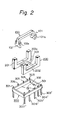
- Fig. 2 is an exploded, perspective view schematically illustrating a first embodiment of the polarized electromagnetic relay according to the present invention;
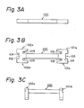
- Fig. 3A is a plan view of the core of Fig. 2 where a bending operation is not carried out;
- Fig. 3B is a front view of the core of Fig. 3A;
- Fig. 3C is a front view of the core of Fig. 2 where a bending operation is carried out;
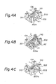
- Figs. 4A, 4B, and 4C are perspective views explaining the operation of the relay of Fig. 2;
- Fig. 5A is a plan view illustrating a completely assembled state of the relay of Fig. 2;
- Fig. 5B is a front view of the relay of Fig. 5A;
- Fig. 6 is an exploded, perspective view illustrating a second embodiment of the polarized electromagnetic relay according to the present invention;
- Fig. 7A is a plan view illustrating a completely assembled state of the relay of Fig. 6; and
- Fig. 7B is a front view of the relay of Fig. 7A.
- First, a prior art polarized electromagnetic relay will be explained with reference to Fig. 1 (See: Unexamined Japanese Patent Publication No. 53-122752).
- In Fig. 1, reference A designates an electromagnet unit, and B designates a contact spring mechanism. The electromagnet unit A is comprised of an
armature block 1,cards 2 and 2ʹ, aseparator 3, and acore 4. - The
armature block 1 is comprised of twoarmatures coupling member 13 made of synthetic resin.Permanent magnets armatures armature block 1 is constructed by insert molding. Also, provided at the center of thecoupling member 13 is ahole 13a. - The
cards 2 and 2ʹ are of an approximately U-shape and are molded from a synthetic resin. Provided inside of thecards 2 and 2ʹ aregrooves armatures step portions armatures cards 2 and 2ʹ, and thus thecards 2 and 2ʹ are accurately positioned at thearmatures - Also, a
stud 31a protrudes from the center of theseparator 3, and thus thearmature block 1 is rotatably mounted on theseparator 3 by inserting thestud 31a thereof into thehole 13a of thearmature block 1. - The
core 4 is wound by a winding 41, and has twomagnetic pole legs 42 and 42ʹ. Theseparator 3 is mounted between the twomagnetic pole legs 42 and 42ʹ, and as a result, the faces of themagnetic pole legs 42 and 42ʹ oppose thearmatures - The contact spring mechanism B is comprised of a
base block 5 providing arecess portion 51, fourmovable contact springs movable contacts stationary contacts movable contacts movable contact springs terminal bases - The
core 4 is mounted on therecess portion 51 of thebase block 5. - In the relay of Fig. 1, when the
winding 41 is excited or non-excited, thearmature block 1 associated with thecards 2 and 2ʹ is rotated with respect to thestud 31a of theseparator 3, and therefore, aside protrusion card 2 and a side protrusion 23ʹ or 24ʹ of the card 2ʹ push against themovable contact spring movable contact spring - As explained above, in the relay of Fig. 1, since the
armature block 1 is located above thecore 4, the thickness of the relay cannot be reduced. Also, due to the presence of theseparator 3, effective use can not be made of the space within the relay, and further, a large number of components is required. - In Fig. 2, which illustrates a first embodiment of the present invention,
reference numeral 100 designates an approximately U-shaped core having twomagnetic pole legs core 100.Reference numeral 200 designates an H-shaped armature block having a pair ofarmatures coupling member 203 which couples thearmatures coupling member 203 is formed by a permanent magnet. Also, provided at the center of thecoupling member 203 is ahole 203a.Reference numeral 300 designates a base block made of synthetic resin. Also, a supportingstud 302 protrudes from a center of arecess portion 301 of thebase block 300. Thebase block 300 is provided with windingterminals 303 and 303ʹ,stationary spring terminals 304 and 304ʹ,movable spring terminals 305 and 305ʹ,stationary spring terminals 306 and 306ʹ, andredundancy terminals 307 and 307ʹ. - The H-shaped
armature block 200 is rotatably mounted on thebase block 300 by inserting the supportingstud 302 thereof into thehole 203a of thecoupling member 203 of the H-shapedarmature block 200. Also, theU-shaped core 100 is mounted on thebase block 300 by fixing the lower sides of themagnetic pole legs base block 300. In this case, themagnetic pole legs armatures faces armatures - The manufacture of the
core 100 of Fig. 2 will be explained with reference to Figs. 3A, 3B, and 3C. Thecore 100 is manufactured by using a press operation considered suitable for mass production, and accordingly, contributes to a lowering of the manufacturing cost. As illustrated in Figs. 3A and 3B, which are a plan view and a front view, respectively, an iron plate is stamped by a press operation.Reference numerals core 100 is fixed to thebase block 300, andreference numerals 105 designate a portion to which a lead piece of the windingterminal 303 is fixed. Themagnetic pole legs core 100 as illustrated in Fig. 3C. - The magnetic circuit of the relay according to the present invention will be explained with reference to Figs. 4A, 4B, and 4C, which show an assembled state of the
U-shaped core 100 and the H-shapedarmature block 200. - In Fig. 4A, a winding 106 wound on the
core 100 is not excited, and in this case, a magnetic circuit is formed by only thepermanent magnet 203. That is, a magnetic flux φ1 generated from thepermanent magnet 203 flows through a path: the N-pole of thepermanent magnet 203 → thearmature 201 → thecore 100 → thearmature 202 → S-pole of thepermanent magnet 203. As a result, one end of each of thearmatures magnetic pole face - In Fig. 4B, when the winding 106 is excited by supplying a current I thereto, to generate a magnetic flux φ2 opposite to the magnetic flux φ1 by the
permanent magnet 203 in thecore 100, the magnetic flux φ2 flows through a path: the core 100 → thearmature 201 → thecore 100, and through a path: the core 100 → thearmature 202 → thecore 100. In this case, the magnetic flux φ2 from thearmature 202 to thecore 100 is opposed by the magnetic flux φ1 generated from thepermanent magnet 203, to generate a repulsion force between the core 100 and thearmature 202. On the other hand, the magnetic flux φ2 from thearmature 201 to thecore 100 is superimposed on the magnetic flux φ1 generated from thepermanent magnet 203 to generate an attraction between the core 100 and thearmature 201. Thus, a repulsion force is generated in a diagonal direction with respect to thehole 203a, and an attraction force is generated in another diagonal direction with respect to thehole 203a. Therefore, theentire armature block 200 is rotated, and as a result, a state as illustrated in Fig. 4C prevails. - In Fig. 4C, the winding 106 is again non-excited by shutting off the current I supplied thereto. In this case, a magnetic flux φ1ʹ is generated from the
permanent magnet 203. - The relay as illustrated in Fig. 2 is completely assembled as illustrated in Figs. 5A and 5B. In Figs. 5A and 5B,
reference numerals stationary spring terminals 304, 304ʹ, 306, and 306ʹ, respectively, andreference numerals terminals 303 and 303ʹ, respectively. Thelead pieces member 507 made of synthetic resin by insert molding and, as a result, thelead pieces reference numerals 105 in Fig. 3B. - Also, in the contact spring mechanism of Figs. 5A and 5B, movable contact springs 508 and 509 are mounted on the
armatures members movable spring terminals 305 and 305ʹ throughconductive members conductive members conductive members conductive members - In Fig. 6, which illustrates a second embodiment of the present invention, driving
cards members armatures -
Tonque pieces 201a (202a) are formed at the armature 201 (202), is aportion 508a provided at the center bottom of the movable contact spring 508 (509) for welding thecoupling portion 508b to the movable spring terminal 305 (305ʹ). The movable contact spring 508 (509) is fixed to theupper portion 305a (305ʹa) of the movable spring terminal 305 (305ʹ) which is insert-molded to thebase block 300. - The driving card 601 (602) has
penetration holes 601a (602a) into which thetonque pieces 201a (202a) are slidably inserted, and a portion 601b (602b) which is fitted to the upper center portion of the movable contact spring 508 (509). Accordingly, the armature 201 (202) is combined with the movable contact spring 508 (509) by the driving card 601 (602), using an adhesive. Note that it is possible for the driving card 601 (602) to slidably support the movable contact spring 508 (509). - All of the components of Fig. 6 are assembled to obtain the relay as illustrated in Figs. 7A and 7B.
- Namely, in the movable connect spring mechanism of the first embodiment, since the movable contact springs 508 and 509 are fixed via the supporting
members armatures stud 302, the amount of sliding contact between the contacts is large, thus increasing the wear of the contacts. Contrary to this, in the second embodiment, when thearmatures stud 302, thearmatures penetration holes driving cards - As explained above, the polarized electromagnetic relay according to the present invention can be made small in size at a low cost, since the relay according to the present invention is thin and the number of components thereof is small, compared with the prior art.
Claims (6)
a base block (300) having a supporting stud (302) protruded from a center of a recess portion of said base block;
an H-shaped armature block (200) including a pair of armatures (201, 202) mounted in parallel and a coupling member (203), made of at least one permanent magnet, for coupling said armatures with each other, said coupling member having a hole (203a) at the center thereof, said H-shaped armature block being rotatably mounted on said base block by inserting said stud of said base block into said hole of said armature block; and
a core (100) having a winding (106) wound thereon, said core having two magnetic pole legs (101, 102) on both sides thereof to form an approximate. U-shape, said core being mounted on said base block by fixing the lower sides of said magnetic pole legs to said base block between said armatures, so that faces of said magnetic pole legs oppose said armatures.
a pair of movable contact springs (508, 509); and
a pair of driving cards (601, 602) for coupling said movable contact springs with said armatures, respectively.
Applications Claiming Priority (4)
| Application Number | Priority Date | Filing Date | Title |
|---|---|---|---|
| JP23519/87 | 1987-02-05 | ||
| JP62023519A JPH088045B2 (en) | 1987-02-05 | 1987-02-05 | Polarized electromagnet device |
| JP154135/87 | 1987-10-09 | ||
| JP1987154135U JPH0515705Y2 (en) | 1987-10-09 | 1987-10-09 |
Publications (3)
| Publication Number | Publication Date |
|---|---|
| EP0277833A2 true EP0277833A2 (en) | 1988-08-10 |
| EP0277833A3 EP0277833A3 (en) | 1990-05-02 |
| EP0277833B1 EP0277833B1 (en) | 1995-05-24 |
Family
ID=26360885
Family Applications (1)
| Application Number | Title | Priority Date | Filing Date |
|---|---|---|---|
| EP88300943A Expired - Lifetime EP0277833B1 (en) | 1987-02-05 | 1988-02-04 | Polarized electromagnetic relay |
Country Status (5)
| Country | Link |
|---|---|
| US (1) | US4843360A (en) |
| EP (1) | EP0277833B1 (en) |
| KR (1) | KR900008639B1 (en) |
| DE (1) | DE3853838T2 (en) |
| HK (1) | HK130896A (en) |
Cited By (3)
| Publication number | Priority date | Publication date | Assignee | Title |
|---|---|---|---|---|
| EP0462841A2 (en) * | 1990-06-20 | 1991-12-27 | Takamisawa Electric Co., Ltd. | Slim-type polarized electromagnetic relay |
| EP0571064A1 (en) * | 1992-05-19 | 1993-11-24 | Takamisawa Electric Co., Ltd. | Polarized electromagnetic relay |
| EP2648203A1 (en) * | 2010-11-30 | 2013-10-09 | Fuji Electric Fa Components & Systems Co., Ltd. | Latching relay |
Families Citing this family (4)
| Publication number | Priority date | Publication date | Assignee | Title |
|---|---|---|---|---|
| JP5991778B2 (en) * | 2012-04-19 | 2016-09-14 | 富士通コンポーネント株式会社 | Electromagnetic relay |
| DE102012207589B3 (en) * | 2012-05-08 | 2013-10-02 | Gruner Ag | Relay with double break |
| GB201215926D0 (en) * | 2012-09-06 | 2012-10-24 | Dialight Europ Ltd | Improvements in rotary actuators |
| KR101447369B1 (en) * | 2013-06-07 | 2014-10-06 | 송 추안 프레시션 컴퍼니 리미티드 | Manufacturing method for relay core |
Citations (4)
| Publication number | Priority date | Publication date | Assignee | Title |
|---|---|---|---|---|
| CH599675A5 (en) * | 1974-05-15 | 1978-05-31 | Hans Sauer | |
| EP0034811A1 (en) * | 1980-02-25 | 1981-09-02 | Siemens Aktiengesellschaft | Polarized magnet system |
| DE3410424A1 (en) * | 1984-03-21 | 1985-09-26 | Sds-Elektro Gmbh, 8024 Deisenhofen | Journal-supported relay |
| DE3520773C1 (en) * | 1985-05-29 | 1989-07-20 | SDS-Relais AG, 8024 Deisenhofen | Electromagnetic relay |
Family Cites Families (1)
| Publication number | Priority date | Publication date | Assignee | Title |
|---|---|---|---|---|
| JPS53122752A (en) * | 1977-03-31 | 1978-10-26 | Matsushita Electric Works Ltd | Polar relay |
-
1988
- 1988-02-02 US US07/151,664 patent/US4843360A/en not_active Expired - Lifetime
- 1988-02-04 DE DE3853838T patent/DE3853838T2/en not_active Expired - Fee Related
- 1988-02-04 EP EP88300943A patent/EP0277833B1/en not_active Expired - Lifetime
- 1988-02-05 KR KR8801085A patent/KR900008639B1/en not_active IP Right Cessation
-
1996
- 1996-07-18 HK HK130896A patent/HK130896A/en not_active IP Right Cessation
Patent Citations (4)
| Publication number | Priority date | Publication date | Assignee | Title |
|---|---|---|---|---|
| CH599675A5 (en) * | 1974-05-15 | 1978-05-31 | Hans Sauer | |
| EP0034811A1 (en) * | 1980-02-25 | 1981-09-02 | Siemens Aktiengesellschaft | Polarized magnet system |
| DE3410424A1 (en) * | 1984-03-21 | 1985-09-26 | Sds-Elektro Gmbh, 8024 Deisenhofen | Journal-supported relay |
| DE3520773C1 (en) * | 1985-05-29 | 1989-07-20 | SDS-Relais AG, 8024 Deisenhofen | Electromagnetic relay |
Cited By (5)
| Publication number | Priority date | Publication date | Assignee | Title |
|---|---|---|---|---|
| EP0462841A2 (en) * | 1990-06-20 | 1991-12-27 | Takamisawa Electric Co., Ltd. | Slim-type polarized electromagnetic relay |
| EP0462841A3 (en) * | 1990-06-20 | 1992-10-14 | Takamisawa Electric Co., Ltd. | Slim-type polarized electromagnetic relay |
| EP0571064A1 (en) * | 1992-05-19 | 1993-11-24 | Takamisawa Electric Co., Ltd. | Polarized electromagnetic relay |
| EP2648203A1 (en) * | 2010-11-30 | 2013-10-09 | Fuji Electric Fa Components & Systems Co., Ltd. | Latching relay |
| EP2648203A4 (en) * | 2010-11-30 | 2014-12-03 | Fuji Elec Fa Components & Sys | Latching relay |
Also Published As
| Publication number | Publication date |
|---|---|
| KR880010453A (en) | 1988-10-08 |
| DE3853838D1 (en) | 1995-06-29 |
| DE3853838T2 (en) | 1996-02-08 |
| EP0277833B1 (en) | 1995-05-24 |
| KR900008639B1 (en) | 1990-11-26 |
| HK130896A (en) | 1996-07-26 |
| EP0277833A3 (en) | 1990-05-02 |
| US4843360A (en) | 1989-06-27 |
Similar Documents
| Publication | Publication Date | Title |
|---|---|---|
| KR890003641B1 (en) | Polar relay | |
| US4727344A (en) | Electromagnetic drive and polarized relay | |
| KR100286010B1 (en) | switch having a magnetized rocker | |
| US4626813A (en) | Electromagnetic drive and polarized relay | |
| GB1586678A (en) | Miniature relay | |
| EP0817230B1 (en) | Electromagnetic contactor | |
| US4843360A (en) | Polarized electromagnetic relay | |
| EP0225038A2 (en) | Polarized electromagnetic relay | |
| EP0173353B1 (en) | Electromagnetic relay with linearly moving armature assembly | |
| US4587502A (en) | Electromagnetic relay | |
| EP0169714B1 (en) | Polarized electromagnetic relay | |
| EP0157029A1 (en) | Electromagnetic drive and polarized relay | |
| US5162764A (en) | Slim-type polarized electromagnetic relay | |
| CN114388304A (en) | Electromagnetic relay | |
| CN112582209A (en) | Relay with a movable contact | |
| EP0169542B1 (en) | Polarized electromagnet relay | |
| EP0355817A2 (en) | Electromagnetic relay | |
| JPH039292Y2 (en) | ||
| EP0127309B1 (en) | Monostable type relay | |
| JPH088045B2 (en) | Polarized electromagnet device | |
| JPS6355741B2 (en) | ||
| JPH0440251Y2 (en) | ||
| JPH0260021A (en) | Electromagnetic relay | |
| EP0137714A1 (en) | Improvements in or relating to relays | |
| JPS6259851B2 (en) |
Legal Events
| Date | Code | Title | Description |
|---|---|---|---|
| PUAI | Public reference made under article 153(3) epc to a published international application that has entered the european phase |
Free format text: ORIGINAL CODE: 0009012 |
|
| 17P | Request for examination filed |
Effective date: 19880224 |
|
| AK | Designated contracting states |
Kind code of ref document: A2 Designated state(s): DE FR GB IT |
|
| PUAL | Search report despatched |
Free format text: ORIGINAL CODE: 0009013 |
|
| AK | Designated contracting states |
Kind code of ref document: A3 Designated state(s): DE FR GB IT |
|
| 17Q | First examination report despatched |
Effective date: 19931006 |
|
| GRAA | (expected) grant |
Free format text: ORIGINAL CODE: 0009210 |
|
| AK | Designated contracting states |
Kind code of ref document: B1 Designated state(s): DE FR GB IT |
|
| ITF | It: translation for a ep patent filed |
Owner name: BUGNION S.P.A. |
|
| REF | Corresponds to: |
Ref document number: 3853838 Country of ref document: DE Date of ref document: 19950629 |
|
| ET | Fr: translation filed | ||
| PLBE | No opposition filed within time limit |
Free format text: ORIGINAL CODE: 0009261 |
|
| STAA | Information on the status of an ep patent application or granted ep patent |
Free format text: STATUS: NO OPPOSITION FILED WITHIN TIME LIMIT |
|
| 26N | No opposition filed | ||
| REG | Reference to a national code |
Ref country code: GB Ref legal event code: IF02 |
|
| PGFP | Annual fee paid to national office [announced via postgrant information from national office to epo] |
Ref country code: FR Payment date: 20050104 Year of fee payment: 18 |
|
| PGFP | Annual fee paid to national office [announced via postgrant information from national office to epo] |
Ref country code: GB Payment date: 20050202 Year of fee payment: 18 |
|
| PG25 | Lapsed in a contracting state [announced via postgrant information from national office to epo] |
Ref country code: IT Free format text: LAPSE BECAUSE OF NON-PAYMENT OF DUE FEES;WARNING: LAPSES OF ITALIAN PATENTS WITH EFFECTIVE DATE BEFORE 2007 MAY HAVE OCCURRED AT ANY TIME BEFORE 2007. THE CORRECT EFFECTIVE DATE MAY BE DIFFERENT FROM THE ONE RECORDED. Effective date: 20050204 |
|
| PGFP | Annual fee paid to national office [announced via postgrant information from national office to epo] |
Ref country code: DE Payment date: 20050228 Year of fee payment: 18 |
|
| PG25 | Lapsed in a contracting state [announced via postgrant information from national office to epo] |
Ref country code: GB Free format text: LAPSE BECAUSE OF NON-PAYMENT OF DUE FEES Effective date: 20060204 |
|
| PG25 | Lapsed in a contracting state [announced via postgrant information from national office to epo] |
Ref country code: DE Free format text: LAPSE BECAUSE OF NON-PAYMENT OF DUE FEES Effective date: 20060901 |
|
| GBPC | Gb: european patent ceased through non-payment of renewal fee |
Effective date: 20060204 |
|
| REG | Reference to a national code |
Ref country code: FR Ref legal event code: ST Effective date: 20061031 |
|
| PG25 | Lapsed in a contracting state [announced via postgrant information from national office to epo] |
Ref country code: FR Free format text: LAPSE BECAUSE OF NON-PAYMENT OF DUE FEES Effective date: 20060228 |