EP0277564B1 - Recorder for a matrix-like recording - Google Patents
Recorder for a matrix-like recording Download PDFInfo
- Publication number
- EP0277564B1 EP0277564B1 EP88100925A EP88100925A EP0277564B1 EP 0277564 B1 EP0277564 B1 EP 0277564B1 EP 88100925 A EP88100925 A EP 88100925A EP 88100925 A EP88100925 A EP 88100925A EP 0277564 B1 EP0277564 B1 EP 0277564B1
- Authority
- EP
- European Patent Office
- Prior art keywords
- heads
- recorder
- tape
- group
- accordance
- Prior art date
- Legal status (The legal status is an assumption and is not a legal conclusion. Google has not performed a legal analysis and makes no representation as to the accuracy of the status listed.)
- Expired - Lifetime
Links
Images

Classifications
-
- G—PHYSICS
- G11—INFORMATION STORAGE
- G11B—INFORMATION STORAGE BASED ON RELATIVE MOVEMENT BETWEEN RECORD CARRIER AND TRANSDUCER
- G11B5/00—Recording by magnetisation or demagnetisation of a record carrier; Reproducing by magnetic means; Record carriers therefor
- G11B5/48—Disposition or mounting of heads or head supports relative to record carriers ; arrangements of heads, e.g. for scanning the record carrier to increase the relative speed
- G11B5/52—Disposition or mounting of heads or head supports relative to record carriers ; arrangements of heads, e.g. for scanning the record carrier to increase the relative speed with simultaneous movement of head and record carrier, e.g. rotation of head
-
- H—ELECTRICITY
- H02—GENERATION; CONVERSION OR DISTRIBUTION OF ELECTRIC POWER
- H02M—APPARATUS FOR CONVERSION BETWEEN AC AND AC, BETWEEN AC AND DC, OR BETWEEN DC AND DC, AND FOR USE WITH MAINS OR SIMILAR POWER SUPPLY SYSTEMS; CONVERSION OF DC OR AC INPUT POWER INTO SURGE OUTPUT POWER; CONTROL OR REGULATION THEREOF
- H02M7/00—Conversion of ac power input into dc power output; Conversion of dc power input into ac power output
- H02M7/003—Constructional details, e.g. physical layout, assembly, wiring or busbar connections
-
- G—PHYSICS
- G11—INFORMATION STORAGE
- G11B—INFORMATION STORAGE BASED ON RELATIVE MOVEMENT BETWEEN RECORD CARRIER AND TRANSDUCER
- G11B5/00—Recording by magnetisation or demagnetisation of a record carrier; Reproducing by magnetic means; Record carriers therefor
- G11B5/48—Disposition or mounting of heads or head supports relative to record carriers ; arrangements of heads, e.g. for scanning the record carrier to increase the relative speed
- G11B5/52—Disposition or mounting of heads or head supports relative to record carriers ; arrangements of heads, e.g. for scanning the record carrier to increase the relative speed with simultaneous movement of head and record carrier, e.g. rotation of head
- G11B5/53—Disposition or mounting of heads on rotating support
-
- G—PHYSICS
- G11—INFORMATION STORAGE
- G11B—INFORMATION STORAGE BASED ON RELATIVE MOVEMENT BETWEEN RECORD CARRIER AND TRANSDUCER
- G11B5/00—Recording by magnetisation or demagnetisation of a record carrier; Reproducing by magnetic means; Record carriers therefor
- G11B5/48—Disposition or mounting of heads or head supports relative to record carriers ; arrangements of heads, e.g. for scanning the record carrier to increase the relative speed
- G11B5/54—Disposition or mounting of heads or head supports relative to record carriers ; arrangements of heads, e.g. for scanning the record carrier to increase the relative speed with provision for moving the head into or out of its operative position or across tracks
- G11B5/55—Track change, selection or acquisition by displacement of the head
- G11B5/5504—Track change, selection or acquisition by displacement of the head across tape tracks
Definitions
- the invention has for its object to provide a head drum for the described matrix-like recording, with which both track paths can be read synchronously and perfectly even with unavoidable tolerances.
- the invention is based on the following findings and considerations.
- readjustment of the lifting movement of the rotating head wheel with a signal obtained from a tracking signal can ensure that the heads of the head wheel exactly follow the tracks written on the tape.
- the heads of the second group of heads are dynamically readjusted by the actuator in the axial direction of the head drum so that these heads also follow the written tracks of the second track.
- the readjustment is carried out by a voltage which is obtained from a sampled tracking signal.
- the position of the second group of heads in the axial direction of the head drum adapts itself dynamically to the position of the first group of heads so that the heads of the first group perfectly follow the traces of the first track and at the same time the heads of the second group perfectly follow the traces of the second Read the track on the magnetic tape.
- this control of the heads of the second group is carried out by an amount which is less than or equal to the width of a half track that the heads follow exactly one track, regardless of whether the heads of the first group and the Heads of the second group scan tracks of the same atomic number in the two lanes and thus the temporal correlation of the sampled signals is correct.
- a time difference remaining during playback between the signals obtained, preferably by a multiple of tracks, can be compensated for by memory during playback. Such memories during playback are required anyway when processing digital signals. With this solution, it is sensible and sufficient to dimension the actuator to a stroke range of +/- half a track width.
- the readjustment of the heads of the second group takes place over such a stroke range that tracks are always present in the two track tracks during playback same ordinal number are sampled and the two sampled signals from the two lanes coincide in time.
- the simultaneous, synchronous and correlated reading of the two track paths achieved by the invention enables a greater variety in the type of recording of the signals.
- Two signals can be written and read at the same time, which must coincide in their temporal position during playback. If necessary, each track can be read for itself.
- the recorder can therefore also be used to record signals that are not correlated with one another on the two track tracks and to read them one after the other in time.
- the recorder is particularly suitable for recording an additional signal or a substitute signal for the signal written on the first track, which e.g. brings an improvement in the signal of the first track, e.g. for recording a supplementary signal for television playback with increased resolution (HDTV).
- HDTV high resolution
- both lanes would then be used in parallel, with a given cassette then only having half the playing time.
- the "normal resolution” operating mode one lane would only be used in the direction of execution, the other lane would only be used in the reverse direction, which would result in twice the playing time of the "normal resolution” operating mode. This results in a compatible interchangeability of resolution and playing time.
- the signal format can be identical in the two lanes and therefore completely compatible.
- the magnetic tape 15 is guided in the direction 33 past the rotating head drum 8 by wrapping it around an angle of approximately 180 °.
- the first group K1 of heads on the magnetic tape writes or reads 15 successive blocks B1, B2 ... with tracks S running approximately parallel to the tape edge.
- the stroke movement 30 is additionally controlled during the reading process by a voltage U1 obtained from a tracking signal that the heads follow the written tracks exactly.
- the group K2 of heads on the lower half of the band H2 writes or reads corresponding blocks Bn, Bn + 1 ... etc.
- no tracks are given on the band 15, so that the exact position of the heads of the group K2 is not tracked must become.
- the distance between the two groups must, however, be set in a reproducible manner in order to ensure that tapes can be exchanged.
- the heads of group K1 are guided exactly along tracks S in the upper half of the band H1 by the voltage U1. Without additional measures, the tolerances of the strip with regard to its transverse dimension would mean that the heads of group K2 would not run exactly on the tracks on the lower half of the strip H2.
- the group K2 of heads is therefore arranged on a symbolically indicated actuator A, which enables the group K2 to be slightly adjusted in the direction 34.
- the actuator is preferably a piezoelectric actuator, as it is known for controlling the heads in video recorders. Such actuators are also referred to as “bimorphs” or as “thickness transducers”.
- the actuator A is controlled by a voltage U2, which is derived from a tracking signal on the band half H2.
- the group K1 is thus controlled by controlling the lifting movement 30 by the voltage U1 to the correct track sequence in the band half H1 and additionally the group K2 with the actuator A to the correct track sequence in the band half H2.
- all heads of group K2 receive the same change in distance from the plane of group K1 from voltage U2 by means of a common actuator A.
- the individual heads of group K2 can also be arranged on separate actuators A, which are then controlled by the same voltage U2.
- the voltage U2 is transmitted as effects of the rotary transformer which transmit head signals.
- the actuator signal U2 can be decoupled via simple low-pass filtering on the head drum 8.
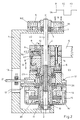
- Fig. 2 shows a structural design of the head drum 8 and the drive 32 for the rotation and the lifting movement 30 in Fig. 1.
- the shaft 4 carrying the threaded spindle 6 is rotatable, but axially immovable stored.
- the upper end of the shaft 4 is connected to the rotor 5 of the motor M2, the stator 7 of which is fixed to the frame 1.
- the head wheel 8, which contains the head disc 12, the first group K1 of heads and the drum 14, is rotatably mounted on the shaft 4 via the slide bearings 9, 10.
- the threaded spindle 6 engages in the nut 11 firmly connected to the drum 14.
- the magnetic tape 15 is guided around the head wheel 8, for example over an angle of 180 °.
- the head drum 8 contains the group K2 of heads, which are mounted on the head drum 8 via the actuator A.
- actuator A is supplied with the voltage U2 for the adjustment in the direction 34.
- the signals are fed from the two head groups K1, K2 via rotating transmitters 23 and flexible lines 17 to the recording or playback amplifiers.
- Separate transformers can also be provided for the groups K1, K2. These are then preferably arranged radially, axially or both radially and axially offset from one another on the head drum 8.
- the rotor 16 of the motor M1 is also attached to the drum 14.
- the stator 19 of the motor M1 is rotatably supported on the drum 14 via the bearings 28, 29 and contains the stator winding 20.
- the stator 19 is connected to the frame 1 via the pin 21 and the bearing 22 so that the pin 21 is movable in the slot 13 of the frame 1 in the axial direction 31, but prevents rotation of the stator 19.
- the parts 9, 10, 11, 12, K1, K2, 14, 16 form the part of the top wheel arrangement rotating about the axis 31.
- the parts 19, 20, 21, 30 form the part of the top wheel arrangement which cannot rotate but can be displaced in the direction of the axis 31 in accordance with the stroke movement.
- the mode of operation is as follows:
- the motor M1 is driven at a speed of about 6000 rpm, so that the top wheel 8 rotates about the axis 31 at this speed.
- the shaft 4 with the threaded spindle 6 is driven by the motor M2 in the same direction as the head wheel 8 and at the same speed. Because of the same number of revolutions, there is no relative movement between the threaded spindle 6 and the nut 11, so that the head wheel 8 rotates but is not moved in the direction of the axis 31. This state is indicated before t1 in FIG. 2.
- the control voltage Us applied to the winding 35 via the terminals 18 is increased, so that the motor M2 runs faster, for example at 6010 rpm.
- the threaded spindle 6 rotates slowly into the nut 11, so that the top wheel 8 desirably executes a lifting movement 30 downwards.
- the control voltage Us and thus the speed of the threaded spindle 6 are reduced accordingly, so that the threaded spindle 6 turns out of the nut 11 and the head wheel 8 is moved upward in the stroke direction 30.
- the jump in amplitude of the voltage Us at t1, t2, t3 thus determines the speed of the lifting movement 30 and the duration t1-t2 or t2-t3 the amplitude of the lifting movement 30.
- An ironless, electronically commutated so-called air coil motor is used for the motor M1 and an electronically commutated flat rotor is used for the motor M2.
- mechanically commutated motors, armature motors and the like can also be used.
- the actuator A dynamically controls the position of the group K2 of heads in the direction 34 in such a way that if the group K1 on the band half H1 has the correct track sequence, the group K2 also exactly follows the tracks on the band half H2.
- the actuator A is ideally set once after the start, specifically to such a deflection that the two magnetic heads which are active at the same time run optimally on one track each of the two band halves H1, H2. After this setting, in the theoretical ideal case, the tracking could take place together, the reference being made from the tracks of only one half of the tape.
Abstract
Description
Bei der sogenannten matrixartigen Aufzeichnung gemäß der DE-OS 35 09 584 werden mit einem rotierenden und in Achsrichtung eine Hubbewegung ausführenden Kopfrad auf einem Magnetband Blöcke mit etwa parallel zur Bandkante verlaufenden, gegenüber der Bandlänge kurzen Spuren geschrieben. Diese Art der Aufzeichnung mit matrixartigen, in Bandlängsrichtung aufeinanderfolgenden Blöcken eignet sich insbesondere für die Aufzeichnung von digitalen Bild- und Tonsignalen und ermöglicht eine bessere Segmentierung der Signale für Sonderfunktionen.In the so-called matrix-like recording according to DE-OS 35 09 584, with a rotating head wheel which executes a stroke movement in the axial direction, blocks are written on a magnetic tape with tracks approximately parallel to the tape edge and short in relation to the tape length. This type of recording with matrix-like blocks which follow one another in the longitudinal direction of the tape is particularly suitable for recording digital image and sound signals and enables better segmentation of the signals for special functions.
Es ist dabei bekannt, mit zwei parallel arbeitenden Abtastsystemen das Magnetband je über die halbe Breite mit zwei Signalen zu beschrieben, z.B. einem hochauflösenden Fernsehsignal (HDTV). Bei dieser Lösung sind also zwei synchron arbeitende rotierende Köpfe oder Gruppen von Köpfen erforderlich.It is known to use two parallel scanning systems to write the magnetic tape over half the width with two signals, e.g. a high definition television signal (HDTV). This solution therefore requires two synchronously rotating heads or groups of heads.
Der Erfindung liegt die Aufgabe zugrunde, für die beschriebene matrixartige Aufzeichnung eine Kopftrommel zu schaffen, mit der auch bei unvermeidbaren Toleranzen beide Spurbahnen synchron und einwandfrei gelesen werden können.The invention has for its object to provide a head drum for the described matrix-like recording, with which both track paths can be read synchronously and perfectly even with unavoidable tolerances.
Diese Aufgabe wird durch die im Anspruch 1 beschriebene Erfindung gelöst. Vorteilhafte Weiterbildungen der Erfindung sind in den Unteransprüchen beschrieben.This object is achieved by the invention described in
Die Erfindung beruht auf folgenden Erkenntnissen und Überlegungen. Beim Lesevorgang bereits geschriebener Spuren kann durch Nachsteuerung der Hubbewegung des rotierenden Kopfrades mit einem aus einem Spurführungssignal gewonnenen Signal erreicht werden, daß die Köpfe des Kopfrades genau den auf dem Band geschriebenen Spuren folgen. Durch mechanische Toleranzen wie z.B. in der Temperatur, dem Bandzug und der Banddehnung ist damit aber nicht sichergestellt, daß dann gleichzeitig die Köpfe der zweiten Gruppe von Köpfen den Spuren der anderen Spurbahn folgen. Deshalb werden erfindungsgemäß die Köpfe der zweiten Gruppe von Köpfen durch den Aktuator in Achsrichtung der Kopftrommel dynamisch so nachgesteuert, daß auch diese Köpfe genau den geschriebenen Spuren der zweiten Spurbahn folgen. Die Nachsteuerung erfolgt dabei durch eine Spannung, die aus einem abgetasten Spurführungssignal gewonnen wird. Die Lage der zweiten Gruppe von Köpfen in Axialrichtung der Kopftrommel paßt sich also dynamisch an die Lage der ersten Gruppe von Köpfen so an, daß die Köpfe der ersten Gruppe einwandfrei die Spuren der ersten Spurbahn und gleichzeitig die Köpfe der zweiten Gruppe einwandfrei die Spuren der zweiten Spurbahn auf den Magnetband lesen.The invention is based on the following findings and considerations. When reading tracks that have already been written, readjustment of the lifting movement of the rotating head wheel with a signal obtained from a tracking signal can ensure that the heads of the head wheel exactly follow the tracks written on the tape. Through mechanical tolerances such as temperature, strip tension and strip stretch, however, this does not ensure that the heads of the second group of heads then follow the traces of the other track at the same time. Therefore, according to the invention, the heads of the second group of heads are dynamically readjusted by the actuator in the axial direction of the head drum so that these heads also follow the written tracks of the second track. The readjustment is carried out by a voltage which is obtained from a sampled tracking signal. The position of the second group of heads in the axial direction of the head drum adapts itself dynamically to the position of the first group of heads so that the heads of the first group perfectly follow the traces of the first track and at the same time the heads of the second group perfectly follow the traces of the second Read the track on the magnetic tape.
Bei einer Ausführungsform der Erfindung erfolgt diese Steuerung der Köpfe der zweiten Gruppe um einen solchen Betrag, der kleiner oder gleich der Breite einer halben Spur ist, daß die Köpfe jeweils genau einer Spur folgen, ohne Rücksicht darauf, ob die Köpfe der ersten Gruppe und die Köpfe der zweiten Gruppe in den beiden Spurbahnen Spuren gleicher Ordnungszahl abtasten und somit die zeitliche Korrelation der abgetasteten Signale stimmt. Eine bei der Wiedergabe verbleibende Zeitabweichung zwischen den gewonnenen Signalen, vorzugsweise um ein Mehrfaches von Spuren, kann durch Speicher bei der Wiedergabe ausgeglichen werden. Derartige Speicher bei der Wiedergabe sind bei der Verarbeitung von digitalen Signalen ohnehin erforderlich. Bei dieser Lösung ist es sinnvoll und ausreichend, den Aktuator auf einen Hubbereich von +/- eine halbe Spurbreite zu bemessen.In one embodiment of the invention, this control of the heads of the second group is carried out by an amount which is less than or equal to the width of a half track that the heads follow exactly one track, regardless of whether the heads of the first group and the Heads of the second group scan tracks of the same atomic number in the two lanes and thus the temporal correlation of the sampled signals is correct. A time difference remaining during playback between the signals obtained, preferably by a multiple of tracks, can be compensated for by memory during playback. Such memories during playback are required anyway when processing digital signals. With this solution, it is sensible and sufficient to dimension the actuator to a stroke range of +/- half a track width.
Bei einer anderen Ausführungsform erfolgt die Nachsteuerung der Köpfe der zweiten Gruppe über einen solchen Hubbereich, daß bei der Wiedergabe in den beiden Spurbahnen stets Spuren gleicher Ordnungszahl abgetastet werden und die beiden abgetasteten Signale von den beiden Spurbahnen zeitlich übereinstimmen.In another embodiment, the readjustment of the heads of the second group takes place over such a stroke range that tracks are always present in the two track tracks during playback same ordinal number are sampled and the two sampled signals from the two lanes coincide in time.
Das durch die Erfindung erreichte gleichzeitige synchrone und korrelierte Lesen der beiden Spurbahnen ermöglicht eine größere Vielfalt in der Art der Aufzeichnung der Signale. Es können zwei Signale jeweils gleichzeitig geschrieben und gelesen werden, die bei der Wiedergabe in ihrer zeitlichen Lage übereinstimmen müssen. Dabei kann im Bedarfsfalle auch jede Spurbahn für sich gelesen werden. Der Recorder kann also auch dazu dienen, auf den beiden Spurbahnen nicht zueinander korrelierte Signale aufzuzeichnen und diese zeitlich nacheinander zu lesen. Der Recorder ist besonders dafür geeignet, zu dem auf der ersten Spurbahn geschriebenen Signal ein ergänzendes Signal oder ein Ersatzsignal aufzuzeichnen, das z.B. eine Verbesserung des Signals der ersten Spurbahn bringt, z.B. zur Aufzeichnung eines ergänzenden Signals für eine Fernsehwiedergabe mit erhöhter Auflösung (HDTV). Bei Wahl der Betriebsart "Höhere Auflösung" würden dann beide Spurbahnen gleichzeitig parallel genutzt, wobei eine vorgegebenen Kassette dann nur die halbe Spielzeit aufweist. In der Betriebsart "Normale Auflösung" würde die eine Spurbahn nur in Hinrichtung, die andere Spurbahn nur in Rückrichtung genutzt, womit sich die doppelte Spielzeit der Betriebsart "Normale Auflösung" ergäbe. Es ergibt sich also eine kompatible Austauschbarkeit von Auflösung und Spielzeit. Das Signalformat kann in den beiden Bahnen identisch und somit vollkommen kompatibel sein.The simultaneous, synchronous and correlated reading of the two track paths achieved by the invention enables a greater variety in the type of recording of the signals. Two signals can be written and read at the same time, which must coincide in their temporal position during playback. If necessary, each track can be read for itself. The recorder can therefore also be used to record signals that are not correlated with one another on the two track tracks and to read them one after the other in time. The recorder is particularly suitable for recording an additional signal or a substitute signal for the signal written on the first track, which e.g. brings an improvement in the signal of the first track, e.g. for recording a supplementary signal for television playback with increased resolution (HDTV). If the "higher resolution" operating mode were selected, both lanes would then be used in parallel, with a given cassette then only having half the playing time. In the "normal resolution" operating mode, one lane would only be used in the direction of execution, the other lane would only be used in the reverse direction, which would result in twice the playing time of the "normal resolution" operating mode. This results in a compatible interchangeability of resolution and playing time. The signal format can be identical in the two lanes and therefore completely compatible.
Die Erfindung wird in folgenden anhand der Zeichnung an einem Ausführungsbeispiel erläutert. Darin zeigen
- Fig. 1
- im Prinzip das Zusammenwirken der Kopftrommel mit dem Magnetband und
- Fig. 2
- eine konstruktive Ausbildung der Kopftrommel und ihres Antriebes.
- Fig. 1
- in principle the interaction of the head drum with the magnetic tape and
- Fig. 2
- a constructive training of the head drum and of their drive.
In Fig. 1 wird das Magnetband 15 in Richtung 33 an der rotierenden Kopftrommel 8 vorbeigeführt, indem es diese über einen Winkel von etwa 180° umschlingt. Die Kopftrommel 8 wird von dem Antriebsmotor 32 in Rotation versetzt und gleichzeitig mittels einer Steuerspannung Us periodisch in Richtung der Achse 31 in Sinne einer Hubbewegung 30 über die halbe Bandbreite H1 = H2 bewegt. Dabei schreibt oder liest die erste Gruppe K1 von Köpfen auf dem Magnetband 15 aufeinanderfolgende Blöcke B1, B2... mit annähernd parallel zur Bandkante verlaufenden Spuren S. Die Hubbewegung 30 wird dabei beim Lesevorgang durch eine aus einem Spurführungssignal gewonnene Spannung U1 zusätzlich so gesteuert, daß die Köpfe genau den geschriebenen Spuren folgen.In Fig. 1, the
Gleichzeitig schreibt oder liest die Gruppe K2 von Köpfen auf der unteren Bandhälfte H2 entsprechende Blöcke Bn, Bn+1... usw. Beim Schreibvorgang sind noch keine Spuren auf dem Band 15 vorgegeben, so daß die genaue Lage der Köpfe der Gruppe K2 nicht nachgeführt werden muß. Der Abstand beider Gruppen muß jedoch für eine Austauschbarkeit von Bändern recht genau reproduzierbar eingestellt werden. Beim Lesevorgang werden die Köpfe der Gruppe K1 durch die Spannung U1 genau entlang den Spuren S in der oberen Bandhälfte H1 geführt. Ohne zusätzliche Maßnahmen würden durch Toleranzen des Bandes bzgl. seiner Querabmessung die Köpfe der Gruppe K2 nicht genau auf den Spuren auf der unteren Bandhälfte H2 verlaufen. Im Idealfall würde ein solcher "Offset" der Köpfe der Gruppe K2 recht konstant sein, da beide Gruppen von Köpfen durch das Spurführungssignal der Köpfe K1 geführt werden. Deshalb ist die Gruppe K2 von Köpfen auf einem symbolisch angedeuteten Aktuator A angeordnet, der eine geringfügige Verstellung der Gruppe K2 in Richtung 34 ermöglicht. Der Aktuator ist vorzugsweise ein piezoelektrischer Aktuator, wie er zur Steuerung der Köpfe bei Videorecordern bekannt ist. Derartige Aktuatoren werden auch als "Bimorph" oder als "Dickenschwinger" bezeichnet. Der Aktuator A wird von einer Spannung U2 gesteuert, die aus einem Spurführungssignal auf der Bandhälfte H2 abgeleitet ist. Die Gruppe K1 wird also durch Steuerung der Hubbewegung 30 durch die Spannung U1 auf korrekte Spurfolge in der Bandhälfte H1 und additiv die Gruppe K2 mit dem Aktuator A auf korrekte Spurfolge in der Bandhälfte H2 gesteuert. Vorzugsweise erhalten alle Köpfe der Gruppe K2 durch die Spannung U2 dieselbe Abstandsänderung von der Ebene der Gruppe K1 durch einen gemeinsamen Aktuator A. Die enzelnen Köpfe der Gruppe K2 können auch auf getrennten Aktuatoren A angeordnet sein, die dann von der gleichen Spannung U2 gesteuert werden. Die Spannung U2 wird als Kopfsignale übertragenden Wirklungen des Drehübertragers übertragen. Die Entkopplung des Aktuatorsignals U2 kann über eine einfache Tiefpaßfilterung auf der Kopftrommel 8 erfolgen.At the same time, the group K2 of heads on the lower half of the band H2 writes or reads corresponding blocks Bn, Bn + 1 ... etc. During the writing process, no tracks are given on the
Fig. 2 zeigt eine konstruktive Ausführung der Kopftrommel 8 und des Antriebs 32 für die Rotation und die Hubbewegung 30 in Fig. 1. In dem ortsfesten Rahmen 1 ist mittels der Lager 2, 3 die die Gewindespindel 6 tragende Welle 4 drehbar, aber axial unverschiebbar gelagert. Das obere Ende der Welle 4 ist mit dem Rotor 5 des Motors M2 verbunden, dessen Stator 7 fest mit dem Rahmen 1 verbunden ist. Das Kopfrad 8, das die Kopfscheibe 12, die erste Gruppe K1 von Köpfen und die Trommel 14 enthält, ist über die Gleitlager 9, 10 drehbar auf der Welle 4 gelagert. Dabei greift die Gewindespindel 6 in die fest mit der Trommel 14 verbundene Mutter 11 ein. Das Magnetband 15 ist um das Kopfrad 8 herumgeführt, z.B. über einen Winkel von 180°. Zusätzlich zu der Gruppe K1 von Köpfen enthält die Kopftrommel 8 die Gruppe K2 von Köpfen, die über den Aktuator A an der Kopftrommel 8 gelagert sind. Dem Aktuator A wird wie in Fig. 1 die Spannung U2 für die Verstellung in Richtung 34 zugeführt. Die Signale werden von den beiden Kopfgruppen K1, K2 über rotierende Übertrager 23 und flexible Leitungen 17 den Aufnahme- oder Wiedergabeverstärkern zugeführt. Es können auch für die Gruppen K1, K2 getrennte Übertrager vorgesehen sein. Diese sind dann vorzugsweise radial, axial oder sowohl radial als auch axial gegeneinander versetzt an der Kopftrommel 8 angeordnet. An der Trommel 14 ist außerdem der Rotor 16 des Motors M1 befestigt. Der Stator 19 des Motors M1 ist über die Lager 28, 29 auf der Trommel 14 relativ zu dieser drehbar gelagert und enthält die Statorwicklung 20. Der Stator 19 ist über den Stift 21 und das Lager 22 so mit dem Rahmen 1 verbunden, daß der Stift 21 in dem Schlitz 13 des Rahmens 1 in Achsialrichtung 31 bewegbar ist, jedoch eine Drehung des Stators 19 verhindert.Fig. 2 shows a structural design of the
Die Teile 9, 10, 11, 12, K1, K2, 14, 16 bilden den um die Achse 31 rotierenden Teil der Kopfradanordnung. Die Teile 19, 20, 21, 30 bilden den Teil der Kopfradanordnung, der nicht rotieren kann, aber entsprechend der Hubbewegung in Richtung der Achse 31 verschiebbar ist.The
Die Wirkungsweise ist folgende: Der Motor M1 wird mit einer Geschwindigkeit von etwa 6000 Upm angetrieben, so daß das Kopfrad 8 mit dieser Drehzahl um die Achse 31 rotiert. Die Welle 4 mit der Gewindespindel 6 wird durch den Motor M2 in der gleichen Richtung wie das Kopfrad 8 und mit der gleichen Umdrehungszahl angetrieben. Wegen der gleichen Umdrehungszahlen besteht zwischen der Gewindespindel 6 und der Mutter 11 keine Relativbewegung, so daß das Kopfrad 8 rotiert, in Richtung der Achse 31 jedoch nicht bewegt wird. In Fig. 2 ist dieser Zustand vor t1 angedeutet. In Zeitpunkt t1 wird die über die Klemmen 18 an die Wicklung 35 angelegte Steuerspannung Us erhöht, so daß der Motor M2 schneller läuft, z.B. mit 6010 Upm. Dadurch dreht sich die Gewindespindel 6 in die Mutter 11 langsam hinein, so daß das Kopfrad 8 in erwünschter Weise eine Hubbewegung 30 nach unten ausführt. Im Zeitpunkt t2 werden die Steuerspannung Us und damit die Drehzahl der Gewindespindel 6 entsprechend verringert, so daß die Gewindespindel 6 sich aus der Mutter 11 herausdreht und das Kopfrad 8 in Hubrichtung 30 nach oben bewegt wird. Der Amplitudensprung der Spannung Us bei t1, t2, t3 bestimmt also die Geschwindigkeit der Hubbewegung 30 und die Dauer t1-t2 oder t2-t3 die Amplitude der Hubbewegung 30.The mode of operation is as follows: The motor M1 is driven at a speed of about 6000 rpm, so that the
Für den Motor M1 wird ein eisenloser, elektronisch kommutierter sogenannter Luftspulenmotor verwendet und für den Motor M2 ein elektronisch kommutierter Flachläufer. Es können jedoch auch mechanisch kommutierte Motoren, Ankermotoren und dgl. verwendet werden.An ironless, electronically commutated so-called air coil motor is used for the motor M1 and an electronically commutated flat rotor is used for the motor M2. However, mechanically commutated motors, armature motors and the like can also be used.
Der Aktuator A steuert wie in Fig. 1 die Lage der Gruppe K2 von Köpfen in Richtung 34 dynamisch derart, daß bei korrekter Spurfolge der Gruppe K1 auf der Bandhälfte H1 auch die Gruppe K2 exakt den Spuren auf der Bandhälfte H2 folgt. Bei Aufnahme wird der Aktuator A stromlos geschaltet, d.h. die Spannung U2 hat dann einen konstanten Wert, der den gewünschten Sollabstand in Axialrichtung zwischen den beiden Gruppen K1, K2 bewirkt. Dieser Abstand ist etwa gleich der halben Breite des Magnetbandes 15, also = H1 = H2. Bei Wiedergabe wird der Aktuator A in Idealfall nach dem Start einmal eingestellt, und zwar auf eine solche Auslenkung, daß die beiden jeweils gleichzeitig aktiven Magnetköpfe optimal auf je einer Spur der beiden Bandhälften H1, H2 laufen. Nach dieser Einstellung könnte im theoretischen Idealfall die Spurführung gemeinsam erfolgen, wobei die Referenz aus den Spuren von nur einer Bandhälfte erfolgen würde.As in FIG. 1, the actuator A dynamically controls the position of the group K2 of heads in the
Claims (10)
- Recorder for a matrix type recording in which blocks (B) are written on a magnetic tape (15) in tracks (S) that are approximately parallel to the edge of the tape and that are short relative to the length of the tape, with a rotating head drum (8) that effects a sweeping motion (30) in the axial direction, wherein a first (K1) and a second (K2) group of heads, displaced in the axial direction (31), is provided on the head drum (8), characterised in that, the two groups are mounted on the head drum (8), displaceable relative to each other in the axial direction (31) by means of an electromechanical actuator (A).
- Recorder in accordance with Claim 1, characterised in that, the actuator (A) and/or the sweeping motion (30) is controlled by an adjusting value (U2, U1) which is obtained from a tracking control signal sampled from the tape (15).
- Recorder in accordance with Claim 1, characterised in that, the sweeping motion (30) is controlled such that the first group (K1) of heads follows the tracks (S) written on a first half (H1) of the tape (15).
- Recorder in accordance with Claim 3, characterised in that, simultaneously with the control of the first group of heads by the tracking control signal, the actuator (A) is controlled such that the second group (K2) of heads follows the tracks written on the second half (H2) of the tape (15) without regard to their ordinal number relative to the ordinal number of the tracks read from the first half (H1) of the tape by the first group (K1) of heads.
- Recorder in accordance with Claim 3, characterised in that, the actuator (A) is controlled such that both groups (K1, K2) of heads always read tracks (S) of similar ordinal number on the two halves (H1, H2) of the tape (15).
- Recorder in accordance with Claim 4, characterised in that, during the reproduction, differences in the temporal ordinal number of the signals read at the same time by the two groups (K1, K2) of heads are balanced out by stores.
- Recorder in accordance with Claim 1, characterised in that, the heads of the second group (K2) are arranged on separate actuators (A) or on a common actuator (A).
- Recorder in accordance with Claim 7, characterised in that, the separate actuators (A) are identical and are controlled by the same signal (U2).
- Recorder in accordance with Claim 1, characterised in that, the distance between the two groups (K1, K2) of heads in the axial direction (31) of the head drum (8) is approximately equal to half the geometrical width (H1, H2) of the tape (15).
- Recorder in accordance with Claim 1, characterised in that, during recording, the control of the actuator (A) is turned-off.
Priority Applications (1)
| Application Number | Priority Date | Filing Date | Title |
|---|---|---|---|
| AT88100925T ATE81918T1 (en) | 1987-01-31 | 1988-01-22 | RECORDER FOR A MATRIX-LIKE RECORDING. |
Applications Claiming Priority (2)
| Application Number | Priority Date | Filing Date | Title |
|---|---|---|---|
| DE3702858 | 1987-01-31 | ||
| DE19873702858 DE3702858A1 (en) | 1987-01-31 | 1987-01-31 | RECORDER FOR A MATRIX-LIKE RECORD |
Publications (3)
| Publication Number | Publication Date |
|---|---|
| EP0277564A2 EP0277564A2 (en) | 1988-08-10 |
| EP0277564A3 EP0277564A3 (en) | 1990-09-12 |
| EP0277564B1 true EP0277564B1 (en) | 1992-10-28 |
Family
ID=6319915
Family Applications (1)
| Application Number | Title | Priority Date | Filing Date |
|---|---|---|---|
| EP88100925A Expired - Lifetime EP0277564B1 (en) | 1987-01-31 | 1988-01-22 | Recorder for a matrix-like recording |
Country Status (8)
| Country | Link |
|---|---|
| EP (1) | EP0277564B1 (en) |
| JP (1) | JPS63200302A (en) |
| KR (1) | KR920001148B1 (en) |
| AT (1) | ATE81918T1 (en) |
| DE (2) | DE3702858A1 (en) |
| ES (1) | ES2035115T3 (en) |
| GR (1) | GR3006919T3 (en) |
| HK (1) | HK120294A (en) |
Families Citing this family (2)
| Publication number | Priority date | Publication date | Assignee | Title |
|---|---|---|---|---|
| DE3830083A1 (en) * | 1988-09-03 | 1990-03-15 | Thomson Brandt Gmbh | Head drum arrangement for a recorder |
| DE19531075A1 (en) * | 1995-08-23 | 1997-02-27 | Thomson Brandt Gmbh | Magnetic tape device for recording and reproducing signals |
Family Cites Families (11)
| Publication number | Priority date | Publication date | Assignee | Title |
|---|---|---|---|---|
| FR509374A (en) * | 1920-02-03 | 1920-11-08 | Louis Badois | Lock nut system |
| US3197575A (en) * | 1960-08-10 | 1965-07-27 | Emil L Eckstein | High density recorder utilizing low tape speed |
| US3213204A (en) * | 1961-03-21 | 1965-10-19 | Nippon Electric Co | Magnetic tape recorder |
| DE2535780C3 (en) * | 1975-08-11 | 1978-10-05 | Igor Alekseewitsch Moskau Kryltsov | Magnetic tape drive for video tape recorders with longitudinal track recording |
| AT349223B (en) * | 1976-08-26 | 1979-03-26 | Eumig | SYSTEM FOR RECORDING AND REPLAYING TELEVISION AND / OR SOUND SIGNALS |
| FR2405536A1 (en) * | 1977-10-07 | 1979-05-04 | Thomson Csf | DEVICE FOR RECORDING-READING INFORMATION ON A LOOP OF MAGNETIC TAPE WRAPPED IN AN ENDLESS CASSETTE |
| JPS5778623A (en) * | 1980-11-04 | 1982-05-17 | Victor Co Of Japan Ltd | Track shift detection system of magnetic reproducing device |
| JPS6129401A (en) * | 1984-07-19 | 1986-02-10 | Sanyo Electric Co Ltd | Double cassette type vtr cylinder device |
| DE3516107A1 (en) * | 1985-03-16 | 1986-11-06 | Deutsche Thomson-Brandt Gmbh, 7730 Villingen-Schwenningen | Process for recording and reproducing a signal on a carrier |
| DE3509584A1 (en) * | 1985-03-16 | 1986-09-18 | Deutsche Thomson-Brandt Gmbh, 7730 Villingen-Schwenningen | Process for recording a signal on a recording carrier in tape form |
| EP0197333B1 (en) * | 1985-03-16 | 1989-12-13 | Deutsche Thomson-Brandt GmbH | Method for recording a signal on a record carrier in the form of a tape |
-
1987
- 1987-01-31 DE DE19873702858 patent/DE3702858A1/en not_active Withdrawn
-
1988
- 1988-01-20 JP JP63008593A patent/JPS63200302A/en active Pending
- 1988-01-22 DE DE8888100925T patent/DE3875496D1/en not_active Expired - Fee Related
- 1988-01-22 AT AT88100925T patent/ATE81918T1/en not_active IP Right Cessation
- 1988-01-22 ES ES198888100925T patent/ES2035115T3/en not_active Expired - Lifetime
- 1988-01-22 EP EP88100925A patent/EP0277564B1/en not_active Expired - Lifetime
- 1988-01-25 KR KR1019880000543A patent/KR920001148B1/en not_active IP Right Cessation
-
1993
- 1993-01-28 GR GR930400166T patent/GR3006919T3/el unknown
-
1994
- 1994-11-03 HK HK120294A patent/HK120294A/en not_active IP Right Cessation
Also Published As
| Publication number | Publication date |
|---|---|
| EP0277564A2 (en) | 1988-08-10 |
| EP0277564A3 (en) | 1990-09-12 |
| GR3006919T3 (en) | 1993-06-30 |
| JPS63200302A (en) | 1988-08-18 |
| ES2035115T3 (en) | 1993-04-16 |
| HK120294A (en) | 1994-11-11 |
| ATE81918T1 (en) | 1992-11-15 |
| KR920001148B1 (en) | 1992-02-06 |
| DE3875496D1 (en) | 1992-12-03 |
| DE3702858A1 (en) | 1988-08-11 |
| KR880009338A (en) | 1988-09-14 |
Similar Documents
| Publication | Publication Date | Title |
|---|---|---|
| DE2941803A1 (en) | RECORDING AND PLAYBACK FOR VIDEO SIGNALS | |
| DE2535780A1 (en) | MAGNETIC TAPE DRIVE FOR VIDEO TAPE DEVICES WITH LONG TRACK RECORDING | |
| DE3045541C2 (en) | ||
| DE3009582A1 (en) | TURNTABLE SWITCHING FOR MAGNETIC RECORDING AND / OR PLAYBACK DEVICES | |
| DE3133727C2 (en) | Reproduction apparatus for a magnetic recording-reproducing apparatus | |
| EP0277564B1 (en) | Recorder for a matrix-like recording | |
| DE3805436A1 (en) | METHOD FOR PLAYING BACK DATA SIGNALS | |
| EP0115275B1 (en) | Video recorder drive | |
| DE4032983C2 (en) | Orbital magnetic head device for a magnetic recording / reproducing apparatus | |
| DE2646899C2 (en) | Method for playing back video signals recorded on magnetic tape | |
| DE3926518A1 (en) | DEVICE FOR MAGNETIC RECORDING AND PLAYBACK | |
| EP0197333B1 (en) | Method for recording a signal on a record carrier in the form of a tape | |
| DE3305618C2 (en) | Head drum for a video magnetic tape recorder | |
| DE2658574C3 (en) | Process for recording and reproducing video signals on magnetic tape | |
| DE3726203A1 (en) | LONGITUDINAL TRACK RECORDING AND / OR PLAYBACK TAPE | |
| DE3509584A1 (en) | Process for recording a signal on a recording carrier in tape form | |
| DE3835075A1 (en) | HEAD SLIDE FOR A RECORDING SYSTEM WITH LONG-TERM RECORDING WITH A ROTATABLE RECORDING AND / OR PLAYBACK HEAD | |
| DE3726767A1 (en) | LIFTING DEVICE FOR A ROTOR | |
| DE2455135C3 (en) | Video signal magnetic recorder and / or reproducer | |
| EP0212592B1 (en) | Recorder, particularly for a digital signal | |
| DE3303290A1 (en) | Coarse and fine adjustment device | |
| DE3538985A1 (en) | CRUISE CONTROL | |
| EP0257562A2 (en) | Lifting device for a rotor, particularly for the head wheel arrangement of a recorder | |
| EP0182901B1 (en) | Magnetic tape apparatus | |
| DE3147596A1 (en) | Method for automatic adjustment of the scanning track in magnetic video tape devices with helical track recording |
Legal Events
| Date | Code | Title | Description |
|---|---|---|---|
| PUAI | Public reference made under article 153(3) epc to a published international application that has entered the european phase |
Free format text: ORIGINAL CODE: 0009012 |
|
| AK | Designated contracting states |
Kind code of ref document: A2 Designated state(s): AT BE CH DE ES FR GB GR IT LI LU NL SE |
|
| PUAL | Search report despatched |
Free format text: ORIGINAL CODE: 0009013 |
|
| AK | Designated contracting states |
Kind code of ref document: A3 Designated state(s): AT BE CH DE ES FR GB GR IT LI LU NL SE |
|
| 17P | Request for examination filed |
Effective date: 19901102 |
|
| 17Q | First examination report despatched |
Effective date: 19920407 |
|
| GRAA | (expected) grant |
Free format text: ORIGINAL CODE: 0009210 |
|
| AK | Designated contracting states |
Kind code of ref document: B1 Designated state(s): AT BE CH DE ES FR GB GR IT LI LU NL SE |
|
| REF | Corresponds to: |
Ref document number: 81918 Country of ref document: AT Date of ref document: 19921115 Kind code of ref document: T |
|
| ITF | It: translation for a ep patent filed |
Owner name: BARZANO' E ZANARDO MILA |
|
| GBT | Gb: translation of ep patent filed (gb section 77(6)(a)/1977) | ||
| REF | Corresponds to: |
Ref document number: 3875496 Country of ref document: DE Date of ref document: 19921203 |
|
| PGFP | Annual fee paid to national office [announced via postgrant information from national office to epo] |
Ref country code: LU Payment date: 19921217 Year of fee payment: 6 |
|
| PGFP | Annual fee paid to national office [announced via postgrant information from national office to epo] |
Ref country code: SE Payment date: 19930113 Year of fee payment: 6 |
|
| PGFP | Annual fee paid to national office [announced via postgrant information from national office to epo] |
Ref country code: BE Payment date: 19930127 Year of fee payment: 6 |
|
| PGFP | Annual fee paid to national office [announced via postgrant information from national office to epo] |
Ref country code: GR Payment date: 19930128 Year of fee payment: 6 |
|
| PGFP | Annual fee paid to national office [announced via postgrant information from national office to epo] |
Ref country code: AT Payment date: 19930129 Year of fee payment: 6 |
|
| PGFP | Annual fee paid to national office [announced via postgrant information from national office to epo] |
Ref country code: NL Payment date: 19930131 Year of fee payment: 6 |
|
| PGFP | Annual fee paid to national office [announced via postgrant information from national office to epo] |
Ref country code: CH Payment date: 19930201 Year of fee payment: 6 |
|
| ET | Fr: translation filed | ||
| EPTA | Lu: last paid annual fee | ||
| REG | Reference to a national code |
Ref country code: ES Ref legal event code: FG2A Ref document number: 2035115 Country of ref document: ES Kind code of ref document: T3 |
|
| REG | Reference to a national code |
Ref country code: GR Ref legal event code: FG4A Free format text: 3006919 |
|
| PLBE | No opposition filed within time limit |
Free format text: ORIGINAL CODE: 0009261 |
|
| STAA | Information on the status of an ep patent application or granted ep patent |
Free format text: STATUS: NO OPPOSITION FILED WITHIN TIME LIMIT |
|
| 26N | No opposition filed | ||
| PG25 | Lapsed in a contracting state [announced via postgrant information from national office to epo] |
Ref country code: LU Free format text: LAPSE BECAUSE OF NON-PAYMENT OF DUE FEES Effective date: 19940122 Ref country code: AT Effective date: 19940122 |
|
| PG25 | Lapsed in a contracting state [announced via postgrant information from national office to epo] |
Ref country code: SE Effective date: 19940123 |
|
| PG25 | Lapsed in a contracting state [announced via postgrant information from national office to epo] |
Ref country code: LI Effective date: 19940131 Ref country code: CH Effective date: 19940131 Ref country code: BE Effective date: 19940131 |
|
| BERE | Be: lapsed |
Owner name: DEUTSCHE THOMSON-BRANDT G.M.B.H. Effective date: 19940131 |
|
| PG25 | Lapsed in a contracting state [announced via postgrant information from national office to epo] |
Ref country code: GR Free format text: THE PATENT HAS BEEN ANNULLED BY A DECISION OF A NATIONAL AUTHORITY Effective date: 19940731 |
|
| PG25 | Lapsed in a contracting state [announced via postgrant information from national office to epo] |
Ref country code: NL Effective date: 19940801 |
|
| NLV4 | Nl: lapsed or anulled due to non-payment of the annual fee | ||
| REG | Reference to a national code |
Ref country code: CH Ref legal event code: PL |
|
| REG | Reference to a national code |
Ref country code: GR Ref legal event code: MM2A Free format text: 3006919 |
|
| EUG | Se: european patent has lapsed |
Ref document number: 88100925.2 Effective date: 19940810 |
|
| REG | Reference to a national code |
Ref country code: GB Ref legal event code: 746 Effective date: 19970909 |
|
| PGFP | Annual fee paid to national office [announced via postgrant information from national office to epo] |
Ref country code: GB Payment date: 19971219 Year of fee payment: 11 |
|
| PGFP | Annual fee paid to national office [announced via postgrant information from national office to epo] |
Ref country code: FR Payment date: 19971231 Year of fee payment: 11 |
|
| PGFP | Annual fee paid to national office [announced via postgrant information from national office to epo] |
Ref country code: DE Payment date: 19980123 Year of fee payment: 11 |
|
| PGFP | Annual fee paid to national office [announced via postgrant information from national office to epo] |
Ref country code: ES Payment date: 19980130 Year of fee payment: 11 |
|
| PG25 | Lapsed in a contracting state [announced via postgrant information from national office to epo] |
Ref country code: GB Free format text: LAPSE BECAUSE OF NON-PAYMENT OF DUE FEES Effective date: 19990122 |
|
| PG25 | Lapsed in a contracting state [announced via postgrant information from national office to epo] |
Ref country code: ES Free format text: LAPSE BECAUSE OF NON-PAYMENT OF DUE FEES Effective date: 19990123 |
|
| GBPC | Gb: european patent ceased through non-payment of renewal fee |
Effective date: 19990122 |
|
| PG25 | Lapsed in a contracting state [announced via postgrant information from national office to epo] |
Ref country code: FR Free format text: LAPSE BECAUSE OF NON-PAYMENT OF DUE FEES Effective date: 19990930 |
|
| PG25 | Lapsed in a contracting state [announced via postgrant information from national office to epo] |
Ref country code: DE Free format text: LAPSE BECAUSE OF NON-PAYMENT OF DUE FEES Effective date: 19991103 |
|
| REG | Reference to a national code |
Ref country code: FR Ref legal event code: ST |
|
| REG | Reference to a national code |
Ref country code: ES Ref legal event code: FD2A Effective date: 20010503 |
|
| PG25 | Lapsed in a contracting state [announced via postgrant information from national office to epo] |
Ref country code: IT Free format text: LAPSE BECAUSE OF NON-PAYMENT OF DUE FEES;WARNING: LAPSES OF ITALIAN PATENTS WITH EFFECTIVE DATE BEFORE 2007 MAY HAVE OCCURRED AT ANY TIME BEFORE 2007. THE CORRECT EFFECTIVE DATE MAY BE DIFFERENT FROM THE ONE RECORDED. Effective date: 20050122 |