EP0277329B1 - A method of adjusting density measurement position - Google Patents
A method of adjusting density measurement position Download PDFInfo
- Publication number
- EP0277329B1 EP0277329B1 EP87118782A EP87118782A EP0277329B1 EP 0277329 B1 EP0277329 B1 EP 0277329B1 EP 87118782 A EP87118782 A EP 87118782A EP 87118782 A EP87118782 A EP 87118782A EP 0277329 B1 EP0277329 B1 EP 0277329B1
- Authority
- EP
- European Patent Office
- Prior art keywords
- sheet
- coordinate
- points
- axis
- density measurement
- Prior art date
- Legal status (The legal status is an assumption and is not a legal conclusion. Google has not performed a legal analysis and makes no representation as to the accuracy of the status listed.)
- Expired - Lifetime
Links
Images





Classifications
-
- B—PERFORMING OPERATIONS; TRANSPORTING
- B41—PRINTING; LINING MACHINES; TYPEWRITERS; STAMPS
- B41F—PRINTING MACHINES OR PRESSES
- B41F33/00—Indicating, counting, warning, control or safety devices
- B41F33/0036—Devices for scanning or checking the printed matter for quality control
-
- G—PHYSICS
- G01—MEASURING; TESTING
- G01N—INVESTIGATING OR ANALYSING MATERIALS BY DETERMINING THEIR CHEMICAL OR PHYSICAL PROPERTIES
- G01N21/00—Investigating or analysing materials by the use of optical means, i.e. using sub-millimetre waves, infrared, visible or ultraviolet light
- G01N21/17—Systems in which incident light is modified in accordance with the properties of the material investigated
- G01N21/59—Transmissivity
- G01N21/5907—Densitometers
- G01N21/5911—Densitometers of the scanning type
-
- G—PHYSICS
- G01—MEASURING; TESTING
- G01N—INVESTIGATING OR ANALYSING MATERIALS BY DETERMINING THEIR CHEMICAL OR PHYSICAL PROPERTIES
- G01N2201/00—Features of devices classified in G01N21/00
- G01N2201/10—Scanning
- G01N2201/101—Scanning measuring head
Definitions
- the present invention relates to a method for adjusting the position of colour density measurement reference points according to the preamble of claim 1.
- the quantity of supplied ink is controlled by using sample sheets on which the pattern is printed so that the density of this pattern can be maintained at a predetermined value.
- the sample sheets 42 as shown in Fig. 12 are usually provided with a belt-shaped solid mark 41 having a predetermined width W.
- This solid mark 41 is printed at an end portion of the sheet 42 in the same processes as the printing of the picture print 40.
- This solid mark 41 is divided in the length direction in various sections, so that the densities of the respective colours can be measured which are assigned to these sections. Thereby an adjustment of the solid mark 41 of the sample sheet 42 to a predetermined position has to be performed on basis of judgement by the human eye.
- the end of the sample sheet 42 can be brought in contact with a guide thereby positioning the sample sheet 42 with regard to the table.
- the densities of the respective colours are scanned and measured by the head unit of a densitometer, whereby the density of pattern 40 is represented by the density of the solid mark 41.
- the measurement area of the head unit of the densitometer falls within the width W of the solid mark 41. Since as a rule the solid mark 41 is broader than the measurement area of the head unit, the position adjustment can be performed rather easily.
- This method however, has the drawback that no direct control or supervision of the picture to be printed is performed because the colour density of the picture is obtained by measuring only the density of the separate solid mark 41. Thus, there may occurs instances, when the colour density of the actual picture 40 to be printed fails to be satisfactory while the density of the separate solid mark 41 is printed in a satisfactory way.
- EP-A-0 131 109 it is already known (see EP-A-0 131 109) to provide paper sheets to be printed with colour strips, so that the particular paper sheet can be scanned by means of an optical pen. From EP-A-0 143 744 it is further known, to make the colour density measurements directly within the pictures already printed thereby avoiding the provision of special colour strips which have to be cut away at a later stage.
- the object of the present invention to provide a method for adjusting the colour density measurement points which by reducing the burden on the operator, allows an extreme exact positioning of colour density measurement points of a reference sheet with regard to the corresponding coordinate positions of colour density measurement points of the following sample sheets, thereby making it possible that the colour density of a pattern to be printed is controlled in a direct way.
- Another object of the present invention is to provide a method for adjusting the colour density measurement position thereby allowing the use of a rather narrow solid mark thus making is possible to save printing paper accordingly.
- the positions of colour density measurement reference points provided on a reference sheet can be adjusted in an extremely precise way with corresponding coordinate positions of the colour density measurement points provided on the following sample sheets.
- FIG. 2 is a perspective view illustrating an embodiment of a density measurement apparatus to which the density measurement position adjustment method is applied.
- This density measurement apparatus includes an X-Y coordinate table 1, a scanning densitometer 2 arranged on the X-Y coordinate table 1 so that it is movable in the X-direction of the X-Y coordinate table 1 (in the left and right directions, i.e., in a transverse direction in the figure) and in the Y-direction thereof (in the front and rear directions in the figure), and an operation unit 3 constructed as a console panel on which various switches, a display and the like are arranged.
- a paper guide 4 is provided on the X-Y coordinate table 1.
- a paper 5 can be positioned and arranged as indicated by single dotted lines in the figure by allowing the paper end to be in contact with the paper guide 4. Further, a plurality of air holes (although not shown) are opened in one side surface of the X-Y coordinate table 1. By sucking air through these air holes, the paper 5 is held, thereby making possible to maintain flatness or evenness thereof on the X-Y coordinate table 1.
- the scanning densitometer 2 is constructed as a reflection type densitometer. In front of a position away from the density measurement area of its head unit, a position adjustment or registering mark 21 is provided.
- Fig. 3 is a block diagram illustrating the circuit arrangement of the above-mentioned density measurement apparatus.
- This density measurement apparatus includes a memory unit 6 for memorizing various data and programs, and a microprocessor 7 to execute data processing and the like in accordance with the programs constructed at the memory unit 6.
- the memory unit 6 and the microprocessor 7 are connected to an input device 31 and a display device 32 at the operation unit 3, a paper sucker 9, the scanning densitometer 2, and a position command circuit 10 through a data and control bus 8. Transmission and receiption of various kind of information may be conducted among these components. For example, A/D conversion of a density value detected at the scanning densitometer 2 is performed in response to a command from the microprocessor 7.
- the density value detected which has undergone A/D conversion is memorized or stored into the memory unit 6.
- the position command circuit 10 conducts transmission and receiption of data to and from an X-axis motor drive circuit 11 and a Y-axis motor drive circuit 12 through data and control buses 11a and 12a.
- the drive control of an X-axis motor 13 is performed by the X-axis motor drive circuit 11 and the drive control of a Y-axis motor 14 is performed by the Y-axis motor drive circuit 12. Namely, movements in X- and Y-directions on the X-Y coordinate table 1 of the scanning densitometer 2 are controlled by the X-axis and Y-axis motors 13 and 14, respectively.
- an OK sheet 51 (Fig. 4) which constitutes a density specimen of a pattern (reference sheet) as the paper 5 is set on the X-Y coordinate table 1 of this density measurement apparatus.
- reference marks 512, 513 and 514 are printed as portions of the pattern depicted at the bottom of the outer peripheral portion of the pattern portion 511. These reference marks 512, 513 and 514 are painted out in the form of rectangle by predetermined widths, respectively.
- the reference marks 512, 513 and 514 constitute reference marks A, B and C, respectively.
- the reference marks A and B are such that their edges in a length direction are arranged on the same straight line and their edges in a width direction are oppositely disposed with they being spaced from each other by a predetermined distance.
- the reference marks B and C cross at right angles at their end portions. Namely, by adjusting the end portion of the OK sheet 51 to which such reference marks are implemented to the paper guide 4, it is positioned and arranged on the X-Y coordinate table 1.
- setting of coordinate positions on the X-Y coordinate table of density measurement desired points (density measurement reference points) and the density measurement at the coordinate points are conducted.
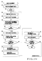
- step 101 when the operation of the flowchart is initiated (step 101), the paper sucker 9 is activated to suck the OK sheet 51 set on the X-Y coordinate table 1 (step 102). From such a condition, X-axis and Y-axis motor manual drive switches (not shown) included in the operation unit 3 are operated to move the scanning densitometer 2, thereby allowing the position adjustment mark 21 of the scanning densitometer 2 to be in correspondence with substantially the center of the reference mark A in a width direction (step 103). Then, a Y-axis switch (not shown) is depressed (step 104).
- a density measurement area 22 of the scanning densitometer 2 is located close to the side portion of the reference mark A(512).
- the Y-axis switch is to be depressed at the step 104.
- a coordinate position RSi(x si , y si ) of a central point P1 of the density measurement area 22 on the X-Y coordinate table 1 at this time is memorized into the memory unit 6 as a head position (step 105).
- the point P1 of the density measurement area 22 begins moving as indicated by single dotted lines and the density measurements caused to corresponding to coordinate positions on the X-Y coordinate table every fixed movement intervals during the movement of the density measurement area 22 are conducted.
- density values caused to correspond to such coordinate positions are memorized into the memory unit 6 (step 107).
- the Y-axis motor manual drive switch is cut off at step 108.
- a coordinate position REi(x Ei , y Ei ) of the point P1 on the X-Y coordinate table 1 at this time is memorized (step 109).
- the coordinate position showing the maximum value of the mountain-shaped waveform data represents the center of the reference mark A in a width direction.
- the coordinates indicative of the center in the width direction are memorized at step 110.
- the program execution returns to the step 103. Namely, for the reference mark B, the positioning mark 21 of the scanning densitometer 2 is adjusted to substantially the center in the width direction of the reference mark B.
- the central coordinates in the width direction thereof are determined at step 110.
- the positioning mark 21 of the scanning densitometer 2 is adjusted to a position which is slightly shifted to the left or right at substantially the center in a length direction of the reference mark C.
- the X-axis switch is depressed at step 104.
- the X-axis motor manual drive switch is turned on at step 106.
- the density measurement area 22 moves in the X-axis direction to scan the reference mark C.
- the central coordinates in the width direction are determined at step 110.
- density values measured are obtained as mountain-shaped data.
- the central coordinates in the width direction can be precisely detected.
- any color may be used. It is preferable that the color of the reference mark is "black” or the like in view of ensurance of clear contrast with respect to the paper.
- color of "visual” or any reference mark may be given by a switch to thereby automatically select a filter corresponding thereto.
- comparison of outputs of all filters of "visual", “Red”, “Green” and “Blue” may be made to thereby employ a value which is maximum at the difference between the vertex and the bottom side of the mountain-shaped waveform.
- the origin on the OK sheet 51 can be expressed as a point at which the straight line AB and a straight line drawn from C to the straight line AB intersect with each other.
- the coordinate transformation setting a point on the X-Y coordinate table 1 which is opposite to the origin of the OK sheet 51 as the position of origin O (0, 0) of the X-Y coordinate table 1 can be realized by a general numeric calculation program. In a manner similar to this, it is possible to set the straight lines AB and OC as the x-axis and y-axis, respectively.
- the microprocessor 7 determines the origin of the OK sheet 51 to consider this origin as the position of origin O (0, 0) on the X-Y coordinate table 1 and to consider the straight lines AB and OC as the x-axis and y-axis, respectively.
- the x-axis and y-axis motor manual drive switches are operated, thereby allowing the positioning mark 21 of the scanning densitometer 2 to be in correspondence with a density measurement desired point within the pattern portion 511 on the OK sheet 51.
- the density measurement area 22 moves on the basis of data indicative of quantity of positional shift between the positioning mark 21 and the density measurement area 22 to adjust the point P1 thereof to the density measurement desired point (step 114).
- a reference value setting switch (not shown) is depressed at step 113
- the density measurement area 22 moves on the basis of data indicative of quantity of positional shift between the positioning mark 21 and the density measurement area 22 to adjust the point P1 thereof to the density measurement desired point (step 114).
- the coordinate position on the X-Y coordinate table 1 at the density measurement desired point is recognized and the density at this point is read, whereby they are memorized as the reference measurement coordinate position and the reference density value (step 115).
- a series of works for setting density measurement reference points and reference densities using the OK sheet is completed at step 117.
- a sample sheet (not shown) is set in place of the OK sheet 51 on the X-Y coordinate table 1 in the same manner as in the OK sheet 51.
- a pattern identical to that on the OK sheet is printed (reference marks A to C are also printed).
- this sample sheet is set on the X-Y coordinate table 1 to initiate the density measurements at respective points on the sample sheet which correspond to density measurement reference points on the OK sheet 51 in accordance with the flowchart shown in Fig. 1(b).
- a measurement switch (not shown) is turned on at step 202.
- the sample sheet is sucked and held on the X-Y coordinate table 1 (step 203) and at the same time the central point P1 of the density measurement area 22 of the scanning densitometer 2 is automatically moved to the coordinate position RSi(x si , y si ) at the step 105 which has been memorized using the OK sheet 51 (step 204).
- the density measurement area 22 moves to a predetermined position close to the reference mark.
- step 205 the X-axis motor 13 or the Y-axis motor is driven (for the reference marks A and B, the Y-axis motor 14 is driven and for the reference mark C, the X-axis motor 13 is driven), the point P1 of the density measurement area 22 begins moving and the density measurements of reference marks caused to correspond to coordinate positions on the X-Y coordinate table 1 are conducted every predetermined movement intervals.
- density values caused to correspond to the coordinate positions are memorized (step 206).
- the X-axis motor 13 or the Y-axis motor 14 is stopped at step 208.
- the central coordinate position in a width direction of the reference mark is determined on the basis of the density measurement result caused to correspond to the above-mentioned coordinate position (step 209).
- the steps 204 to 209 are repeatedly executed until the result of step 210 becomes Y to determine central coordinate positions A ⁇ , B ⁇ and C ⁇ in respective width directions of the reference marks A, B and C.
- the origin on the sample sheet is determined. Namely, a vertical line is drawn from C ⁇ to the straight line A ⁇ B ⁇ to determine a point at which the vertical line and the straight line A ⁇ B ⁇ intersect with each other to be the origin O ⁇ and to apply coordinate transformation to a point on the X-Y coordinate table 1 which is opposite to the origin of the sample sheet to be the position of origin O(O, O).
- the straight lines A ⁇ B ⁇ and O ⁇ C ⁇ may be set to the x-axis and y-axis, respectively.
- the microprocessor 7 performs the above coordinate transformation to thereby consider the origin on the sample sheet as the position of origin O(O, O) on the X-Y coordinate table 1 and to consider the straight lines A ⁇ B ⁇ and O ⁇ C ⁇ as the x-axis and the y-axis, respectively.
- the coordinate position of origin and the x- and y-axis on the OK sheet 51 and the coordinate position of origin and x- and y-axis on the sample sheet are in correspondence with each other on the X-Y coordinate table 1.
- the position of the density measurement point corresponding to the density measurement reference point is corrected (step 212).
- the density measurement reference point on the OK sheet 51 and the density measurement point on the sample sheet are in correspondence with each other on the coordinate of the X-Y coordinate table 1.
- the scanning densitometer automatically moves, so that the point P1 of the density measurement area 22 is precisely located at the density measurement point on the sample sheet which is in correspondence with the coordinate position of the density measurement reference point of the OK sheet 51 (step 213).
- the density measurement at this point is conducted (step 214).
- the density measurements of density measurement points on the sample sheet corresponding to all density measurement reference points on the OK sheet are determined by repeatedly executing the steps 211 to 214 until the result of the step 215 becomes Y.
- the density measurement values at respective measurement points are memorized in correspondence with the reference density values at the density measurement reference points on the OK sheet 51.
- Fig. 6 shows an example of a flowchart for conducting a pertinent control of a quantity of an ink supplied to a printing machine on the basis of the result having been explained to effect a density control of a printing picture.
- the density control is initiated at step 301, data related to a paper size is read at step 302. Then, at step 303, the coordinate position on the X-Y coordinate table 1 of the density measurement reference point having been determined using the OK sheet 51 is read. A correspondence divisional blade number in the printing machine which corresponds to the coordinate position thus read is memorized (step 304).
- Fig. 7 is a side cross sectional view showing the essential part of the ink supply unit in the printing machine.
- the relationship in respect of the supply quantity of the ink 17, the printing density and the density difference varies in accordance with the kind of the printing machine.
- the blade opening quantity HI is adjusted to thereby adjust an ink supply quantity, thus to perform a density control.
- the relationship in respect of the ink supply quantity, the printing density and the density difference is memorized in advance as data caused to correspond to a printing machine employed. As shown in Fig.
- the blade 15 is disposed in a range broader than the width W1 of the paper 18 to be printed and is composed of a plurality of divisional blades 151 to 1524 of which blade opening quantities are independently adjustable.
- predetermined blade numbers of No. 1 to No. 24 as shown are assigned, respectively. Since the paper 18 to be printed is fed to the printing machine with the paper central line indicated by single dotted lines in the figure being in correspondence with the center of the printing machine, the center in a transverse direction of the printed paper is adjusted to the center of the X-Y coordinate table by the paper guide. Accordingly, the positional relationship between the divisional blades and the density measurement points can be determined using width values of respective blades which can be known in advance.
- step 303 For example, where a coordinate position of a density measurement reference point corresponding to the point P2 shown in Fig. 8 is read at step 303, the divisional blade 158 corresponding to the density measurement desired point thus read is selected. As a result, No. 8 which is the blade number thereof is memorized at step 304. Then, at step 305, the difference between the reference density of the density measurement reference point on the OK sheet and the density measured value of the sample sheet having been memorized in correspondence therewith is computed. By repeatedly executing the steps 303 to 305 until the result of the step 306 becomes Y, correspondence blade numbers for the all density measurement points are memorized and density differences between the all density measurement points and reference densities of the all density measurement reference points are determined.
- step 307 whether or not density measurement points of which blade numbers overlap with each other are present is confirmed. If density measurement points of which blade numbers overlap with each other are present, the average of the density difference between density measured values and reference densities at these density measurement points is computed at step 308. The program execution shifts to step 309. In contrast, if density measurement points of which blade numbers overlap with each other are not present, the program execution directly shifts to the step 309. At this step 309, correcting quantities of the blade opening quantities of the divisional blades corresponding to the respective density measurement points are computed on the basis of the density differences. In accordance with the correcting quantities thus computed, blade opening quantities of respective blades are corrected (step 310).
- densities at points corresponding to respective density measurement points of the printing paper 18 which is to be printed from now are precisely in correspondence with the reference densities having been determined using the OK sheet.
- densities or density values defined in this embodiment are values obtained by implementing color separation to measure respective values of "Cyan”, “Magenta”, “Yellow” and "Black”.
- the density measurement position adjustment method can conduct a density control of a pattern using narrower reference marks A to C without use of the broder solid mark 41 as shown in Fig. 12. This permits a quantity of papers to be cut after printing to be reduced to save papers accordingly. Moreover, since the density of the pattern is directly measured, the precision of the density control is extremely improved as compared to the conventional method to make a measurement using a solid mark. Further, the densities of significant portions of the pattern can be selectively supervised, resulting in high control efficiency. Furthermore, the scanning densitometer is used for detecting origins on the OK sheet and the sample sheet, resulting in simplified structure, low cost and high precision in the agreement between detection positions and measurement positions.
- the reference marks A to C are printed at the bottom portion of the paper in this embodiment, it is preferable that they are printed at the central portion of the paper in an actual sense. Namely, the longitudinal length of a paper may be expanded by about 1 mm by the application of printing pressure to the paper. Where portions to which the density control is applied are not solid portions in a pattern but significant points for printing of halftone portions therein, even if there occurs positional displacement of only 0.1 mm, the measured densities greately change at portions where tone continuously varies. For this reason, it is preferable to print reference marks at the central portion of a paper where the influence of expansion and contraction of the paper on results of computation for correction of position is small even if expansion and contraction of the paper might occur to some extent. Such an implementation permits precise density control. In addition, reference density values at density measurement reference points may be manually input. On the display device 32, coordinate positions, density measured values and the like on the X-Y coordinate table of the scanning densitometer 2 are displayed.
- reference marks B and C are printed in a manner that they intersect with each other in this embodiment, they do not necessarily intersect with each other but may be printed with they being spaced from each other.
- the directions of moving the scanning densitometer after reference marks are designated are different for reference marks A and B and for reference mark A, respectively. Such directions vary depending upon how the OK sheet and the sample sheet are placed on the X-Y coordinate table.
- the sequence of scanning is determined in advance, thereby making it possible to automatically set its moving direction.
- the moving direction can be automatically determined when an arrangement pattern of reference marks is registered into a memory without prescribing the placement manner of the OK sheet and the sample sheet and the positional relationship with respect to respective reference marks thus to allow an operator to select the arrangement pattern, the moving direction can be automatically determined.
- any portions serving as a reference may be selected from the pattern to thereby designate lines in X- and Y-axis directions on the basis of the portions serving as the reference to consider then as reference marks.
- it is desirable that the center of the portion considered as the reference mark is not selected as a reference, but the position of the density gradient designated at the rising portion or at the falling portion of the boundary thereof is selected as a reference. For example, it is assumed that a character of "PT" as shown in Fig.
- the scanning densitometer is moved in a Y-axis direction with respect to the character "PT" to thereby set a reference point D (a first reference point) at the time of rise of the density gradient. Then, by the movement of the scanning densitometer in the Y-axis direction with respect to the character "T", a reference point E (a second reference point) is set at the time of rise of the density gradient. Likewise, by the movement of the scanning densitometer in the X-axis direction with respect to the character "P", a reference point F (a third reference point) is set at the time of rise of the density gradient.
- Such settings are made for the OK sheet set on the X-Y coordinate table.
- a sample sheet 20 is set, e.g., at a position shifted as indicated by broken lines in this figure relative to an OK sheet 19 indicated by a solid line in this figure. Accordingly, the character "PT" of the sample sheet 20 is shifted in appearance relative to the character "PT" of the OK sheet 19 as indicated by broken lines in the figure.
- points corresponding to D, E and F on the OK sheet 19 obtained by the scanning operation using the scanning densitometer are obtained as D ⁇ , E ⁇ and F ⁇ , respectively.
- Such a coordinate transformation may be accomplished by the steps of obtaining an inclination angle ⁇ from the coordinate positions of the reference points D ⁇ and E ⁇ , correcting an aberration in a rotational direction of the character "PT" by this inclination angle ⁇ , thereafter moving the character "PT" for the purpose of allowing the Y-coordinate of the reference point D ⁇ to be in correspondence with the Y-coordinate of the reference point D, and further moving the character "PT" for the purpose of allowing the X-coordinate of the reference point F ⁇ to be in correspondence with the X-axis of the reference point F.
- the density measurement position adjustment method comprises the step of: setting a reference sheet on which a predetermined pattern is printed on an X-Y coordinate table; designating at least three reference points referred to as first to third reference points within the pattern of the reference sheet; determining coordinate positions on the X-Y coordinate table of the three reference points; memorizing coordinate positions at density measurement reference points within the pattern of the reference sheet with a single point and two intersecting lines obtained by computation based on the coordinate positions of the reference points being as an origin, an X-axis and a Y-axis, respectively; setting a sample sheet on which the same pattern as the pattern on the reference sheet is printed on the X-Y coordinate table; detecting coordinate positions on the X-Y coordinate table of points, which correspond to the three reference points on the reference sheet, within the pattern on the sample sheet; determining a detection origin, a detection X-axis and a detection Y-axis by computation based on the coordinate positions of the points on the sample sheet; and correcting coordinate positions
Landscapes
- General Health & Medical Sciences (AREA)
- Immunology (AREA)
- Physics & Mathematics (AREA)
- Health & Medical Sciences (AREA)
- Life Sciences & Earth Sciences (AREA)
- Chemical & Material Sciences (AREA)
- Analytical Chemistry (AREA)
- Biochemistry (AREA)
- Quality & Reliability (AREA)
- Engineering & Computer Science (AREA)
- General Physics & Mathematics (AREA)
- Pathology (AREA)
- Inking, Control Or Cleaning Of Printing Machines (AREA)
- Investigating Or Analysing Materials By Optical Means (AREA)
- Silver Salt Photography Or Processing Solution Therefor (AREA)
- Spectrometry And Color Measurement (AREA)
- Accessory Devices And Overall Control Thereof (AREA)
- Analysing Materials By The Use Of Radiation (AREA)
Abstract
Description
- The present invention relates to a method for adjusting the position of colour density measurement reference points according to the preamble of
claim 1. - In the process of printing sheets it has become common that the quantity of supplied ink is controlled by using sample sheets on which the pattern is printed so that the density of this pattern can be maintained at a predetermined value. For this purpose the
sample sheets 42 as shown in Fig. 12 are usually provided with a belt-shapedsolid mark 41 having a predetermined width W. Thissolid mark 41 is printed at an end portion of thesheet 42 in the same processes as the printing of thepicture print 40. Thissolid mark 41 is divided in the length direction in various sections, so that the densities of the respective colours can be measured which are assigned to these sections. Thereby an adjustment of thesolid mark 41 of thesample sheet 42 to a predetermined position has to be performed on basis of judgement by the human eye. Alternatively the end of thesample sheet 42 can be brought in contact with a guide thereby positioning thesample sheet 42 with regard to the table. In the following the densities of the respective colours are scanned and measured by the head unit of a densitometer, whereby the density ofpattern 40 is represented by the density of thesolid mark 41. When making such a density measurement, it is usually sufficient that the measurement area of the head unit of the densitometer falls within the width W of thesolid mark 41. Since as a rule thesolid mark 41 is broader than the measurement area of the head unit, the position adjustment can be performed rather easily. This method, however, has the drawback that no direct control or supervision of the picture to be printed is performed because the colour density of the picture is obtained by measuring only the density of the separatesolid mark 41. Thus, there may occurs instances, when the colour density of theactual picture 40 to be printed fails to be satisfactory while the density of the separatesolid mark 41 is printed in a satisfactory way. - In order to control the colour density of a picture to be printed in a better way, it is necessary to position certain colour density measurement points of a reference sheet, on which the pattern is to be printed with a prescribed colour density, precisely in correspondence with the density measurement points of following sample sheets. However whenever such an attempt is made to control the colour density of the pattern to be printed separately from the scanning of the solid mark, there arises the possibility that a slight deviation of the measurement position can lead to a relatively large error of the density measurement. Since the positional relationship between the edge of the paper and the pattern to be printed is not necessarily fixed, quite likely problems do occur when adjusting the position of the sample sheets along the guide of the table. Since a position adjustment based on the judgement by the human eye is rather difficult to perform the workability of this method is rather poor.
- In view of this situation it is already known (see EP-A-0 131 109) to provide paper sheets to be printed with colour strips, so that the particular paper sheet can be scanned by means of an optical pen. From EP-A-0 143 744 it is further known, to make the colour density measurements directly within the pictures already printed thereby avoiding the provision of special colour strips which have to be cut away at a later stage.
- In view of this prior art it is the object of the present invention to provide a method for adjusting the colour density measurement points which by reducing the burden on the operator, allows an extreme exact positioning of colour density measurement points of a reference sheet with regard to the corresponding coordinate positions of colour density measurement points of the following sample sheets, thereby making it possible that the colour density of a pattern to be printed is controlled in a direct way.
- Another object of the present invention is to provide a method for adjusting the colour density measurement position thereby allowing the use of a rather narrow solid mark thus making is possible to save printing paper accordingly.
- The above-mentioned objects are achieved by providing the method steps as stated within
claim 1. - Preferred ways for performing the method of the invention are specified within the subclaims 2-27.
- Within the framework of the invention the positions of colour density measurement reference points provided on a reference sheet can be adjusted in an extremely precise way with corresponding coordinate positions of the colour density measurement points provided on the following sample sheets.
-
- Fig. 1 is a flowchart showing an embodiment of a density measurement position adjustment method according to the present invention,
- Fig. 2 is a perspective view illustrating one example of a density measurement apparatus to which the density measurement position adjustment method is applied,
- Fig. 3 is a block diagram showing the circuit arrangement of the density measurement apparatus shown in Fig. 2,
- Fig. 4 is a view showing an OK sheet set on an X-Y coordinate table of the density measurement apparatus,
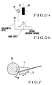
- Fig. 5 is a view showing a movement locus of a scanning densitometer moving across the reference mark printed on the OK sheet and waveform data of density values measured by the densitometer,
- Fig. 6 is a flowchart showing a density control applied to a printing paper in a printing machine which is based on a density measurement result of a sample sheet caused to correspond to the OK sheet,
- Fig. 7 is a cross sectional view showing the essential part of an ink supply unit in a printing machine,
- Fig. 8 is a view showing the correspondence arrangement relationship between the printing paper and the divisional blade in a printing machine,
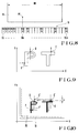
- Fig. 9 is a view showing a character "PT" considered as a reference mark in the pattern,
- Fig. 10 is a view showing a shift of a character "PT" based on the positional shift of the OK sheet and the sample sheet set on an X-Y coordinate table,
- Fig. 11 is a view showing another example of printing arrangement state of a character "PT", and
- Fig. 12 is a view showing a conventional sample sheet on which a belt-shaped solid mark is printed.
- A density measurement position adjustment method will be described in detail with reference to attached drawings. Fig. 2 is a perspective view illustrating an embodiment of a density measurement apparatus to which the density measurement position adjustment method is applied. This density measurement apparatus includes an X-Y coordinate table 1, a
scanning densitometer 2 arranged on the X-Y coordinate table 1 so that it is movable in the X-direction of the X-Y coordinate table 1 (in the left and right directions, i.e., in a transverse direction in the figure) and in the Y-direction thereof (in the front and rear directions in the figure), and anoperation unit 3 constructed as a console panel on which various switches, a display and the like are arranged. On the X-Y coordinate table 1, apaper guide 4 is provided. Thus, apaper 5 can be positioned and arranged as indicated by single dotted lines in the figure by allowing the paper end to be in contact with thepaper guide 4. Further, a plurality of air holes (although not shown) are opened in one side surface of the X-Y coordinate table 1. By sucking air through these air holes, thepaper 5 is held, thereby making possible to maintain flatness or evenness thereof on the X-Y coordinate table 1. Thescanning densitometer 2 is constructed as a reflection type densitometer. In front of a position away from the density measurement area of its head unit, a position adjustment or registeringmark 21 is provided. - Fig. 3 is a block diagram illustrating the circuit arrangement of the above-mentioned density measurement apparatus. This density measurement apparatus includes a memory unit 6 for memorizing various data and programs, and a microprocessor 7 to execute data processing and the like in accordance with the programs constructed at the memory unit 6. The memory unit 6 and the microprocessor 7 are connected to an input device 31 and a
display device 32 at theoperation unit 3, apaper sucker 9, thescanning densitometer 2, and aposition command circuit 10 through a data andcontrol bus 8. Transmission and receiption of various kind of information may be conducted among these components. For example, A/D conversion of a density value detected at thescanning densitometer 2 is performed in response to a command from the microprocessor 7. The density value detected which has undergone A/D conversion is memorized or stored into the memory unit 6. Theposition command circuit 10 conducts transmission and receiption of data to and from an X-axis motor drive circuit 11 and a Y-axismotor drive circuit 12 through data andcontrol buses X-axis motor 13 is performed by the X-axis motor drive circuit 11 and the drive control of a Y-axis motor 14 is performed by the Y-axismotor drive circuit 12. Namely, movements in X- and Y-directions on the X-Y coordinate table 1 of thescanning densitometer 2 are controlled by the X-axis and Y-axis motors position command circuit 10, rotational angles corresponding thereto are transmitted to the X-axis and Y-axis drive circuits axis motors axis motors control bus 8 via theposition command circuit 10. - The density measurement position adjustment method using the density measurement apparatus thus configured will be now explained. First, an OK sheet 51 (Fig. 4) which constitutes a density specimen of a pattern (reference sheet) as the
paper 5 is set on the X-Y coordinate table 1 of this density measurement apparatus. On theOK sheet 51,reference marks pattern portion 511. Thesereference marks reference marks OK sheet 51 to which such reference marks are implemented to thepaper guide 4, it is positioned and arranged on the X-Y coordinate table 1. In accordance with the flowchart shown in Fig. 1(a), setting of coordinate positions on the X-Y coordinate table of density measurement desired points (density measurement reference points) and the density measurement at the coordinate points are conducted. - Namely, when the operation of the flowchart is initiated (step 101), the
paper sucker 9 is activated to suck theOK sheet 51 set on the X-Y coordinate table 1 (step 102). From such a condition, X-axis and Y-axis motor manual drive switches (not shown) included in theoperation unit 3 are operated to move thescanning densitometer 2, thereby allowing theposition adjustment mark 21 of thescanning densitometer 2 to be in correspondence with substantially the center of the reference mark A in a width direction (step 103). Then, a Y-axis switch (not shown) is depressed (step 104). Namely, by adjusting thepositioning mark 21 to the reference mark A, adensity measurement area 22 of thescanning densitometer 2 is located close to the side portion of the reference mark A(512). In such a condition, the Y-axis switch is to be depressed at thestep 104. A coordinate position RSi(xsi, ysi) of a central point P1 of thedensity measurement area 22 on the X-Y coordinate table 1 at this time is memorized into the memory unit 6 as a head position (step 105). Thus, by turning the Y-axis motor manual drive switch on atstep 106, the point P1 of thedensity measurement area 22 begins moving as indicated by single dotted lines and the density measurements caused to corresponding to coordinate positions on the X-Y coordinate table every fixed movement intervals during the movement of thedensity measurement area 22 are conducted. Thus, density values caused to correspond to such coordinate positions are memorized into the memory unit 6 (step 107). Then, after thedensity measurement area 22 transverses the reference mark A, the Y-axis motor manual drive switch is cut off atstep 108. A coordinate position REi(xEi, yEi) of the point P1 on the X-Y coordinate table 1 at this time is memorized (step 109). Fig. 5(b) shows a density change characteristic at the time of movement of the point P1 wherein density values measured are obtained as mountain-shaped waveform data as shown in this figure. Namely, the coordinate position showing the maximum value of the mountain-shaped waveform data represents the center of the reference mark A in a width direction. The coordinates indicative of the center in the width direction are memorized atstep 110. Thus, whether or not central coordinates in the width direction for three reference marks have been determined is condirmed atstep 111. When they have not been determined, the program execution returns to thestep 103. Namely, for the reference mark B, thepositioning mark 21 of thescanning densitometer 2 is adjusted to substantially the center in the width direction of the reference mark B. Then, scanning operation is implemented in the same manner as in the case of the reference mark A. Thus, the central coordinates in the width direction thereof are determined atstep 110. Further, for the reference mark C, thepositioning mark 21 of thescanning densitometer 2 is adjusted to a position which is slightly shifted to the left or right at substantially the center in a length direction of the reference mark C. Then, the X-axis switch is depressed atstep 104. The X-axis motor manual drive switch is turned on atstep 106. Thus, thedensity measurement area 22 moves in the X-axis direction to scan the reference mark C. As a result, the central coordinates in the width direction are determined atstep 110. Also for the reference marks B and C, density values measured are obtained as mountain-shaped data. It is to be noted that when setting is made such that the width of each reference mark is narrower than thedensity measurement area 22, even if the central point P1 of thedensity measurement area 22 does not move transversely on the reference mark in a manner rectangular thereto, the central coordinates in the width direction can be precisely detected. For color of the reference mark, any color may be used. It is preferable that the color of the reference mark is "black" or the like in view of ensurance of clear contrast with respect to the paper. For the filter of thescanning densitometer 2 at the time of detection of the reference mark, color of "visual" or any reference mark may be given by a switch to thereby automatically select a filter corresponding thereto. In addition, comparison of outputs of all filters of "visual", "Red", "Green" and "Blue" may be made to thereby employ a value which is maximum at the difference between the vertex and the bottom side of the mountain-shaped waveform. - Assuming now that the central coordinate positions in the width directions of the reference marks A, B and C are represented by A, B and C, respectively, the origin on the
OK sheet 51 can be expressed as a point at which the straight line AB and a straight line drawn from C to the straight line AB intersect with each other. The coordinate transformation setting a point on the X-Y coordinate table 1 which is opposite to the origin of theOK sheet 51 as the position of origin O (0, 0) of the X-Y coordinate table 1 can be realized by a general numeric calculation program. In a manner similar to this, it is possible to set the straight lines AB and OC as the x-axis and y-axis, respectively. Namely, subsequently to thestep 111, the microprocessor 7 determines the origin of theOK sheet 51 to consider this origin as the position of origin O (0, 0) on the X-Y coordinate table 1 and to consider the straight lines AB and OC as the x-axis and y-axis, respectively. Atstep 112, the x-axis and y-axis motor manual drive switches are operated, thereby allowing thepositioning mark 21 of thescanning densitometer 2 to be in correspondence with a density measurement desired point within thepattern portion 511 on theOK sheet 51. Subsequently, when a reference value setting switch (not shown) is depressed atstep 113, thedensity measurement area 22 moves on the basis of data indicative of quantity of positional shift between thepositioning mark 21 and thedensity measurement area 22 to adjust the point P1 thereof to the density measurement desired point (step 114). Thus, on the basis of the movement position of the point P1 of thisdensity measurement area 22, the coordinate position on the X-Y coordinate table 1 at the density measurement desired point is recognized and the density at this point is read, whereby they are memorized as the reference measurement coordinate position and the reference density value (step 115). By repeatedly executingsuch steps 112 to 115 until the result ofstep 116 becomes Y, it is possible to arbitorarily set a large number of density measurement reference points. - Thus, a series of works for setting density measurement reference points and reference densities using the OK sheet is completed at
step 117. Then, a sample sheet (not shown) is set in place of theOK sheet 51 on the X-Y coordinate table 1 in the same manner as in theOK sheet 51. On this sample sheet, a pattern identical to that on the OK sheet is printed (reference marks A to C are also printed). At a process for printing work, it may be extracted arbitorarily for a density checking. Namely, this sample sheet is set on the X-Y coordinate table 1 to initiate the density measurements at respective points on the sample sheet which correspond to density measurement reference points on theOK sheet 51 in accordance with the flowchart shown in Fig. 1(b). First, a measurement switch (not shown) is turned on atstep 202. Thus, the sample sheet is sucked and held on the X-Y coordinate table 1 (step 203) and at the same time the central point P1 of thedensity measurement area 22 of thescanning densitometer 2 is automatically moved to the coordinate position RSi(xsi, ysi) at thestep 105 which has been memorized using the OK sheet 51 (step 204). Namely, thedensity measurement area 22 moves to a predetermined position close to the reference mark. Then, atstep 205, theX-axis motor 13 or the Y-axis motor is driven (for the reference marks A and B, the Y-axis motor 14 is driven and for the reference mark C, theX-axis motor 13 is driven), the point P1 of thedensity measurement area 22 begins moving and the density measurements of reference marks caused to correspond to coordinate positions on the X-Y coordinate table 1 are conducted every predetermined movement intervals. Thus, density values caused to correspond to the coordinate positions are memorized (step 206). When the point P1 of thedensity measurement area 22 is in correspondence with the coordinate position REi(xEi, yEi) at thestep 109 which has been memorized using the OK sheet 51 (step 207), theX-axis motor 13 or the Y-axis motor 14 is stopped atstep 208. Thus, the central coordinate position in a width direction of the reference mark is determined on the basis of the density measurement result caused to correspond to the above-mentioned coordinate position (step 209). Namely, thesteps 204 to 209 are repeatedly executed until the result ofstep 210 becomes Y to determine central coordinate positions Aʹ, Bʹ and Cʹ in respective width directions of the reference marks A, B and C. From the central coordinate positions Aʹ, Bʹ and Cʹ in the width directions, the origin on the sample sheet is determined. Namely, a vertical line is drawn from Cʹ to the straight line AʹBʹ to determine a point at which the vertical line and the straight line AʹBʹ intersect with each other to be the origin Oʹ and to apply coordinate transformation to a point on the X-Y coordinate table 1 which is opposite to the origin of the sample sheet to be the position of origin O(O, O). In a manner similar to this, the straight lines AʹBʹ and OʹCʹ may be set to the x-axis and y-axis, respectively. Namely, subsequently to thestep 210, the microprocessor 7 performs the above coordinate transformation to thereby consider the origin on the sample sheet as the position of origin O(O, O) on the X-Y coordinate table 1 and to consider the straight lines AʹBʹ and OʹCʹ as the x-axis and the y-axis, respectively. Namely, the coordinate position of origin and the x- and y-axis on theOK sheet 51 and the coordinate position of origin and x- and y-axis on the sample sheet are in correspondence with each other on the X-Y coordinate table 1. By reading the coordinate position (reference measurement position) of the density measurement reference point determined using theOK sheet 51 atstep 211, the position of the density measurement point corresponding to the density measurement reference point is corrected (step 212). Thus, the density measurement reference point on theOK sheet 51 and the density measurement point on the sample sheet are in correspondence with each other on the coordinate of the X-Y coordinate table 1. Then, the scanning densitometer automatically moves, so that the point P1 of thedensity measurement area 22 is precisely located at the density measurement point on the sample sheet which is in correspondence with the coordinate position of the density measurement reference point of the OK sheet 51 (step 213). Thus, the density measurement at this point is conducted (step 214). The density measurements of density measurement points on the sample sheet corresponding to all density measurement reference points on the OK sheet are determined by repeatedly executing thesteps 211 to 214 until the result of thestep 215 becomes Y. The density measurement values at respective measurement points are memorized in correspondence with the reference density values at the density measurement reference points on theOK sheet 51. - Fig. 6 shows an example of a flowchart for conducting a pertinent control of a quantity of an ink supplied to a printing machine on the basis of the result having been explained to effect a density control of a printing picture. When the density control is initiated at
step 301, data related to a paper size is read atstep 302. Then, atstep 303, the coordinate position on the X-Y coordinate table 1 of the density measurement reference point having been determined using theOK sheet 51 is read. A correspondence divisional blade number in the printing machine which corresponds to the coordinate position thus read is memorized (step 304). Fig. 7 is a side cross sectional view showing the essential part of the ink supply unit in the printing machine. By adjusting the opening quantity (blade opening quantity) H1 for theink supply roller 16 of theblade 15, or by adjusting the rotational frequency of theink supply roller 16, it is possible to adjust a supply quantity of theink 17. The relationship in respect of the supply quantity of theink 17, the printing density and the density difference varies in accordance with the kind of the printing machine. In this embodiment, the blade opening quantity HI is adjusted to thereby adjust an ink supply quantity, thus to perform a density control. The relationship in respect of the ink supply quantity, the printing density and the density difference is memorized in advance as data caused to correspond to a printing machine employed. As shown in Fig. 8, theblade 15 is disposed in a range broader than the width W1 of thepaper 18 to be printed and is composed of a plurality ofdivisional blades 15₁ to 15₂₄ of which blade opening quantities are independently adjustable. To thedivisional blades 15₁ to 15₂₄, predetermined blade numbers of No. 1 to No. 24 as shown are assigned, respectively. Since thepaper 18 to be printed is fed to the printing machine with the paper central line indicated by single dotted lines in the figure being in correspondence with the center of the printing machine, the center in a transverse direction of the printed paper is adjusted to the center of the X-Y coordinate table by the paper guide. Accordingly, the positional relationship between the divisional blades and the density measurement points can be determined using width values of respective blades which can be known in advance. For example, where a coordinate position of a density measurement reference point corresponding to the point P2 shown in Fig. 8 is read atstep 303, thedivisional blade 158 corresponding to the density measurement desired point thus read is selected. As a result, No. 8 which is the blade number thereof is memorized atstep 304. Then, at step 305, the difference between the reference density of the density measurement reference point on the OK sheet and the density measured value of the sample sheet having been memorized in correspondence therewith is computed. By repeatedly executing thesteps 303 to 305 until the result of thestep 306 becomes Y, correspondence blade numbers for the all density measurement points are memorized and density differences between the all density measurement points and reference densities of the all density measurement reference points are determined. Then, atstep 307, whether or not density measurement points of which blade numbers overlap with each other are present is confirmed. If density measurement points of which blade numbers overlap with each other are present, the average of the density difference between density measured values and reference densities at these density measurement points is computed atstep 308. The program execution shifts to step 309. In contrast, if density measurement points of which blade numbers overlap with each other are not present, the program execution directly shifts to thestep 309. At thisstep 309, correcting quantities of the blade opening quantities of the divisional blades corresponding to the respective density measurement points are computed on the basis of the density differences. In accordance with the correcting quantities thus computed, blade opening quantities of respective blades are corrected (step 310). By the correction of the blade opening quantities, densities at points corresponding to respective density measurement points of theprinting paper 18 which is to be printed from now are precisely in correspondence with the reference densities having been determined using the OK sheet. It is to be noted that densities or density values defined in this embodiment are values obtained by implementing color separation to measure respective values of "Cyan", "Magenta", "Yellow" and "Black". - As just described above, the density measurement position adjustment method according to this embodiment can conduct a density control of a pattern using narrower reference marks A to C without use of the broder
solid mark 41 as shown in Fig. 12. This permits a quantity of papers to be cut after printing to be reduced to save papers accordingly. Moreover, since the density of the pattern is directly measured, the precision of the density control is extremely improved as compared to the conventional method to make a measurement using a solid mark. Further, the densities of significant portions of the pattern can be selectively supervised, resulting in high control efficiency. Furthermore, the scanning densitometer is used for detecting origins on the OK sheet and the sample sheet, resulting in simplified structure, low cost and high precision in the agreement between detection positions and measurement positions. In addition, placing a sample sheet at a predetermined position on the X-Y coordinate table 1 must be conducted with a considerable care. In accordance with this embodiment, even if a sample sheet is roughly placed, the coordinate position is corrected by making use of the software, resulting in extremely light burden on an operation. - While the reference marks A to C are printed at the bottom portion of the paper in this embodiment, it is preferable that they are printed at the central portion of the paper in an actual sense. Namely, the longitudinal length of a paper may be expanded by about 1 mm by the application of printing pressure to the paper. Where portions to which the density control is applied are not solid portions in a pattern but significant points for printing of halftone portions therein, even if there occurs positional displacement of only 0.1 mm, the measured densities greately change at portions where tone continuously varies. For this reason, it is preferable to print reference marks at the central portion of a paper where the influence of expansion and contraction of the paper on results of computation for correction of position is small even if expansion and contraction of the paper might occur to some extent. Such an implementation permits precise density control. In addition, reference density values at density measurement reference points may be manually input. On the
display device 32, coordinate positions, density measured values and the like on the X-Y coordinate table of thescanning densitometer 2 are displayed. - While the reference marks B and C are printed in a manner that they intersect with each other in this embodiment, they do not necessarily intersect with each other but may be printed with they being spaced from each other. The directions of moving the scanning densitometer after reference marks are designated are different for reference marks A and B and for reference mark A, respectively. Such directions vary depending upon how the OK sheet and the sample sheet are placed on the X-Y coordinate table. When setting is made such that the manner how the OK sheet and the sample sheet are placed is always fixed and the positional relationship of the reference marks A to C is unchanged, the sequence of scanning is determined in advance, thereby making it possible to automatically set its moving direction. In addition, when an arrangement pattern of reference marks is registered into a memory without prescribing the placement manner of the OK sheet and the sample sheet and the positional relationship with respect to respective reference marks thus to allow an operator to select the arrangement pattern, the moving direction can be automatically determined.
- While specified reference marks are printed at the same time when a pattern is printed in this embodiment, since crossed marks called dragon-fly marks are ordinarily printed on the printed matter, those dragon-fly marks may be utilized for the reference marks. Such reference marks are not necessarily used. Instead, any portions serving as a reference may be selected from the pattern to thereby designate lines in X- and Y-axis directions on the basis of the portions serving as the reference to consider then as reference marks. In this case, it is desirable that the center of the portion considered as the reference mark is not selected as a reference, but the position of the density gradient designated at the rising portion or at the falling portion of the boundary thereof is selected as a reference. For example, it is assumed that a character of "PT" as shown in Fig. 9 is considered as the reference mark from the pattern. In this instance, the scanning densitometer is moved in a Y-axis direction with respect to the character "PT" to thereby set a reference point D (a first reference point) at the time of rise of the density gradient. Then, by the movement of the scanning densitometer in the Y-axis direction with respect to the character "T", a reference point E (a second reference point) is set at the time of rise of the density gradient. Likewise, by the movement of the scanning densitometer in the X-axis direction with respect to the character "P", a reference point F (a third reference point) is set at the time of rise of the density gradient. Such settings are made for the OK sheet set on the X-Y coordinate table. From coordinate positions on the X-Y coordinate table of these reference points D to F, the origin, the x-axis and the y-axis are similarly determined. Thus, coordinates at density measurement desired points are memorized with them being as reference. Then, a sample sheet is set on the X-Y coordinate table. In a manner similar to the above, scans in the X-axis direction and in the Y-axis direction with respect to the character "P" and scan in the Y-axis direction with respect to the character "T" are performed using the scanning densitometer. In this instance, the set positions of the OK sheet and the sample sheet are delicately different from each other on the X-Y coordinate table. Namely, as shown in Fig. 10, a
sample sheet 20 is set, e.g., at a position shifted as indicated by broken lines in this figure relative to anOK sheet 19 indicated by a solid line in this figure. Accordingly, the character "PT" of thesample sheet 20 is shifted in appearance relative to the character "PT" of theOK sheet 19 as indicated by broken lines in the figure. Thus, points corresponding to D, E and F on theOK sheet 19 obtained by the scanning operation using the scanning densitometer are obtained as Dʹ, Eʹ and Fʹ, respectively. Namely, it is sufficient for copying with this to implement transformation of coordinate positions on the X-Y coordinate table with a view to allowing coordinate positions of reference points Dʹ, Eʹ and Fʹ on thesample sheet 20 to be in correspondence with coordinate positions of reference points D, E and F on theOK sheet 19. Such a coordinate transformation may be accomplished by the steps of obtaining an inclination angle ϑ from the coordinate positions of the reference points Dʹ and Eʹ, correcting an aberration in a rotational direction of the character "PT" by this inclination angle ϑ, thereafter moving the character "PT" for the purpose of allowing the Y-coordinate of the reference point Dʹ to be in correspondence with the Y-coordinate of the reference point D, and further moving the character "PT" for the purpose of allowing the X-coordinate of the reference point Fʹ to be in correspondence with the X-axis of the reference point F. - It is to be noted that it is sufficient that Y-coordinates of the reference points D and E are not necessarily in correspondence with each other for the character "PT". Namely, it is enough that the upper end surface line of "P" and that of "T" are not linearly in correspondence with each other. For example, even if characters are arranged in the form of stair-steps as shown in Fig. 11, similar coordinate transformation can applied such an arrangement. In addition, while the character "PT" is considered as the reference mark in this embodiment, it is needless to say that various patterns may be similarly considered as the reference mark.
- As described in detail, the density measurement position adjustment method according to the present invention comprises the step of: setting a reference sheet on which a predetermined pattern is printed on an X-Y coordinate table; designating at least three reference points referred to as first to third reference points within the pattern of the reference sheet; determining coordinate positions on the X-Y coordinate table of the three reference points; memorizing coordinate positions at density measurement reference points within the pattern of the reference sheet with a single point and two intersecting lines obtained by computation based on the coordinate positions of the reference points being as an origin, an X-axis and a Y-axis, respectively; setting a sample sheet on which the same pattern as the pattern on the reference sheet is printed on the X-Y coordinate table; detecting coordinate positions on the X-Y coordinate table of points, which correspond to the three reference points on the reference sheet, within the pattern on the sample sheet; determining a detection origin, a detection X-axis and a detection Y-axis by computation based on the coordinate positions of the points on the sample sheet; and correcting coordinate positions of density measurement points, which correspond to the density measurement points on the reference sheet, within the pattern on the sample sheet so that the detection origin, detection X-axis and detection Y-axis are in correspondence with the origin, Y-axis and Y-axis, respectively.
- Accordingly, in accordance with this method, on the X-Y coordinate table, coordinate positions of density measurement reference points on the reference sheet are in correspondence with coordinate positions of density measurement points on the sample sheet. Thus, the direct supervision of the density of a pattern can be conducted extremely pricisely with a lessened burden on an operator. In addition, a broder solid mark is not used as in the prior art, with the result that printing papers can be saved accordingly.
Claims (27)
- Method of adjusting the density measurement position in order to allow coordinate positions of density measurement points (A'-C', D'-F')of a sample sheet (20) placed on an X-Y table (1) to be in correspondence with coordinate positions of density measurements reference points (A-C, D-F) of a reference sheet (19, 51) including the following steps:a) setting up a reference sheet (19, 51) being provided with a predetermined printed pattern (511) on an X-Y coordinate table (1),b) designating on said reference sheet (19, 51) at least three reference points (A-C, D-F) arranged either within said pattern (511) or printed as outer peripheral portions (512-514) of said pattern (511) of said reference sheet (19, 51),c) determining on said X-Y coordinate table (1) the coordinate positions of said three reference points (A-C, D-F) of the reference sheet (19, 51)d) computing a single point and two intersecting lines based on said coordinate positions of said reference points (A-C, D-F) being the origin, the X-axis and the Y-axis, respectively of the reference sheet (19, 51),e) memorizing the coordinate positions of the density measurement reference points within said pattern (511) of said reference sheet (19, 51) by using said single point and said two intersecting lines,f) setting up on said X-Y coordinate table (1) a sample sheet (20) being provided with the same pattern (511) as said pattern (511) of said reference sheet (19, 51),g) detecting the coordinate positions (A'-C', D'-F') of the points (A'-C', D'-F') on said sample sheet (20), which correspond to the three reference points (A-C, D-F) on said reference sheet (19, 51),h) determining the detection origin, the detection X-axis and the detection Y-axis by computation based on said coordinate positions of said points (A'-C', D'-F') on said sample sheet (20) andi) correcting the coordinate positions of density measurement points, which correspond to the density measurement points on said reference sheet (19, 51) within said pattern (511) on said sample sheet (20, 42) so that the detection origin, the detection X-axis and the detection Y-axis of the sample sheet (20) are in correspondence with said the origin, the X-axis and the Y-axis of the reference sheet (19, 51).
- Method according to claim 1, characterized in that said the first reference point (D) is lying on a first axis set on said reference sheet (19, 51), while said second reference point (E) is present on said first axis or an axis parallel thereto in a manner that said second reference point (E) is spaced from said first reference point (D) and that the third reference point (F) is present on a second axis vertical to said first axis.
- Method according to claim 2, characterized in said that the reference points (D-F) are in the form of reference marks (512-514) of predetermined area which are printed in advance on said reference sheet (19, 51) as portions of said pattern (511).
- Method according to claim 3, characterized in that the coordinate positions of said reference points (D-F) are determined on the basis of changes in densities measured by scanning said respective reference marks (512-514) by means of a scanning densitometer (2).
- Method according to claim 3, characterized in that the densities measured by said scanning densitometer (2) are obtained in form of peak-shaped data.
- Method according to claim 3, characterized in that the first and second reference marks (512, 513) are provided in a manner that their edges in the length direction are disposed on the same straight line while their edges in the width direction are oppositely disposed and spaced from each other by a predetermined distance, and that the second and third reference marks (513, 514) intersect each other perpendicularly at their end portions.
- Method according to claim 4, characterized in that the coordinate positions of said reference points (D-F) are determined as detected coordinate positions when the central point of the density measurement area of said scanning densitometer (2) is positioned at the central portions of said reference marks (512-514).
- Method according to claim 7, characterized in that the width of the reference marks (512-514) is narrower than said density measurement area of said scanning densitometer (2).
- Method according to claim 3, characterized in that the reference marks (512-514) are in the form of rectangular areas painted out.
- Method according to claim 9, characterized in that the reference marks (512-514) are coloured black.
- Method according to claim 7, characterized in that when the central coordinate positions in the width directions of said first to third reference marks (512-514) are denoted as A, B and C, respectively, the origin on said reference sheet (19, 51) is expressed as point O at which the straight line AB and a straight line drawn perpendicularly from C intersect with each other.
- Method according to claim 11, characterized in that the origin on said reference sheet (19, 51) is transformed to the origin said X-Y coordinate table (1) by performing a predetermined coordinate transformation.
- Method according to claim 7, characterized in that the straight lines AB and OC on said reference sheet (19, 51) are transformed to the X-axis and the Y-axis on said X-Y coordinate table (1) respectively by performing a predetermined coordinate transformation.
- Method according to claim 7, characterized in that in case that the central coordinate positions in the width directions of points, which correspond to said reference points (A-C) on said reference sheets (19, 51) are denoted as A', B' and C' on said sample sheet (20), the origin on said sample sheet (20) is expressed as a point O' at which the straight line A'B' and the straight line drawn perpendicularly from C' intersect with each other.
- Method according to claim 14, characterized in that the origin on said sample sheet (20) is transformed to the origin on said X-Y coordinate table (1) by performing a predetermined coordinate transformation.
- Method according to claim 14, characterized in that the straight lines A'B' and O'C' on said reference sheet (19, 51) are transformed to the X-axis and the Y-axis on said X-Y coordinate table (1) respectively by performing a predetermined coordinate transformation.
- Method according to claim 1, characterized in that the reference points (D-F) are obtained by utilizing predetermined portions (P,T) of said pattern (511) as they are on said reference sheet (19, 51).
- Method according to claim 17, characterized in that the coordinate positions of said reference points (D-F) are determined on the basis of changes in densities measured by scanning said respective reference marks (P,T) by means a scanning densitometer (2).
- Method according to claim 18, characterized in that the coordinate positions of said reference points (D-F) are determined as coordinate positions detected when the central point of density measurement area of said scanning densitometer (2) transverses individual boundary portions of said predetermined areas of said reference marks (P, T).
- Method according to claim 1, characterized in that when there is a difference between the set positions on said X-Y coordinate table (1) of said reference sheet (19, 51) and said sample sheet (20) said step for correction includes the step for performing a coordinate transformation in order to adjust the coordinate positions of said points which correspond to said reference points (D-F) on said sample sheet (20) to the coordinate positions of said reference points (A-C, D-F)) on said reference sheet (19, 51).
- Method according to claim 20, characterized in that the coordinate transformation is performed by determining the inclination angle (Θ) defined by said points, which correspond to said reference points (D'-F') on said sample sheet (20) based on computation where upon said coordinate position is used in order to correct the aberration in the rotational direction by using said inclination angle (Θ) while in the following the corresponding points on said sample sheet (20) are shifted so that said coordinate positions of said points (D'-F') on said sample sheet (20) are in correspondence with those of said reference points (D-F) on said reference sheet (19,51).
- Method according to claim 21, characterized in that the second and third reference points (E, F) are offset against the axis on which said first reference point (D) is present.
- Method according to claim 22, characterized in that the correction of said coordinate positions of density measurement positions within said pattern (511) on said sample sheet (20) is performed by making use of substantially the same coordinate transformation as said coordinate transformation.
- Method according to claim 2, characterized in that the reference marks (P,T) are printed substantially at the central portion of said reference sheet (19, 51).
- Method according to claim 1, characterized in that the operation for adjusting the density measurement positions is made on the basis of changes in densities measured by scanning respective reference marks (512-514; P,T) by means of scanning densitometer (2).
- Method according to one of the claims 1-25, characterized in that the circuit for performing said operation using said scanning densitometer (2) includes a computer-controlled circuit (3, 6, 7), a position command circuit (10) including motor drive circuits (11, 12) for driving X- and Y-axis motors (12, 13) and a paper sucker (9) for sucking said reference and sample sheets (19, 20, 51) onto said X-Y coordinate table (1).
- Method according to claim 26, characterized in that the computer-controlled circuit (3, 6, 7) comprises a memory unit (6) for memorizing various data and programs, a microprocessor (7) for performing data processing in accordance with a program constructed in said memory unit (6) and an operation unit (3) including an input device for setting necessary input data such as reference density values at said reference measurement reference points (A-C, D-F) and a display device (32) on which coordinate positions, density measured values and the like are displayed.
Priority Applications (1)
| Application Number | Priority Date | Filing Date | Title |
|---|---|---|---|
| AT87118782T ATE103241T1 (en) | 1987-02-03 | 1987-12-17 | ADJUSTMENT PROCEDURES FOR THE LOCATION OF A PAINT DENSITY MEASUREMENT. |
Applications Claiming Priority (2)
| Application Number | Priority Date | Filing Date | Title |
|---|---|---|---|
| JP21879/87 | 1987-02-03 | ||
| JP62021879A JPS63191041A (en) | 1987-02-03 | 1987-02-03 | Concentration measurement positioning method |
Publications (3)
| Publication Number | Publication Date |
|---|---|
| EP0277329A2 EP0277329A2 (en) | 1988-08-10 |
| EP0277329A3 EP0277329A3 (en) | 1990-07-18 |
| EP0277329B1 true EP0277329B1 (en) | 1994-03-23 |
Family
ID=12067409
Family Applications (1)
| Application Number | Title | Priority Date | Filing Date |
|---|---|---|---|
| EP87118782A Expired - Lifetime EP0277329B1 (en) | 1987-02-03 | 1987-12-17 | A method of adjusting density measurement position |
Country Status (5)
| Country | Link |
|---|---|
| US (1) | US4949284A (en) |
| EP (1) | EP0277329B1 (en) |
| JP (1) | JPS63191041A (en) |
| AT (1) | ATE103241T1 (en) |
| DE (1) | DE3789440T2 (en) |
Families Citing this family (24)
| Publication number | Priority date | Publication date | Assignee | Title |
|---|---|---|---|---|
| US5359702A (en) * | 1988-08-31 | 1994-10-25 | Fuji Photo Film Co., Ltd. | Image signal interface system |
| JPH02103446A (en) * | 1988-10-12 | 1990-04-16 | Maruzen Petrochem Co Ltd | Density pattern analysis device |
| DE4004056A1 (en) * | 1990-02-10 | 1991-08-14 | Roland Man Druckmasch | Inking control esp. for offset rotary printing machine - applies colour pattern corrections before addn. of values extracted by scanning system from original colour documents |
| US5208655A (en) * | 1991-08-07 | 1993-05-04 | Graphics Microsystems, Inc. | Method and apparatus for automatic densitometer alignment |
| US5841955A (en) * | 1991-12-02 | 1998-11-24 | Goss Graphic Systems, Inc. | Control system for a printing press |
| DE4321179A1 (en) * | 1993-06-25 | 1995-01-05 | Heidelberger Druckmasch Ag | Method and device for controlling or regulating the operations of a printing machine |
| WO1996008703A1 (en) * | 1994-09-14 | 1996-03-21 | X-Rite, Incorporated | Scanning colorimeter |
| US5812705A (en) * | 1995-02-28 | 1998-09-22 | Goss Graphic Systems, Inc. | Device for automatically aligning a production copy image with a reference copy image in a printing press control system |
| US5767980A (en) * | 1995-06-20 | 1998-06-16 | Goss Graphic Systems, Inc. | Video based color sensing device for a printing press control system |
| US5814405A (en) * | 1995-08-04 | 1998-09-29 | W. L. Gore & Associates, Inc. | Strong, air permeable membranes of polytetrafluoroethylene |
| US5805280A (en) * | 1995-09-28 | 1998-09-08 | Goss Graphic Systems, Inc. | Control system for a printing press |
| US5903712A (en) * | 1995-10-05 | 1999-05-11 | Goss Graphic Systems, Inc. | Ink separation device for printing press ink feed control |
| US6382101B1 (en) * | 1997-03-04 | 2002-05-07 | Heidelberg Harris, Inc. & Heidelberger Druckmaschinen | Remote ink fountain selection method and apparatus |
| US6613203B1 (en) | 2001-09-10 | 2003-09-02 | Gore Enterprise Holdings | Ion conducting membrane having high hardness and dimensional stability |
| US8038013B2 (en) * | 2007-03-06 | 2011-10-18 | E.I. Du Pont De Nemours And Company | Liquid filtration media |
| US7993523B2 (en) * | 2007-03-06 | 2011-08-09 | E. I. Du Pont De Nemours And Company | Liquid filtration media |
| DE102007015097A1 (en) * | 2007-03-29 | 2008-10-02 | Heidelberger Druckmaschinen Ag | Colorimeter with coordinate adjustment |
| JP4572951B2 (en) * | 2008-04-11 | 2010-11-04 | 富士ゼロックス株式会社 | Recording material moving apparatus and image forming apparatus |
| WO2010065949A1 (en) * | 2008-12-05 | 2010-06-10 | E. I. Du Pont De Nemours And Company | Filter media with nanoweb layer |
| DE102013211403B4 (en) * | 2013-06-18 | 2020-12-17 | Carl Zeiss Smt Gmbh | Method and device for the automated determination of a reference point of an alignment mark on a substrate of a photolithographic mask |
| US20160075914A1 (en) | 2014-09-12 | 2016-03-17 | W. L. Gore & Associates, Inc. | Porous Air Permeable Polytetrafluoroethylene Composites with Improved Mechanical and Thermal Properties |
| US9862859B2 (en) | 2014-09-12 | 2018-01-09 | W. L. Gore & Associates, Inc. | Porous air permeable polytetrafluoroethylene composites with improved mechanical and thermal properties |
| WO2016047378A1 (en) * | 2014-09-26 | 2016-03-31 | 富士フイルム株式会社 | Measurement position presentation method, measurement position presentation guide production method, printed matter measurement method, printed matter measurement position determination method, and printed matter measurement position determination device |
| EP3253196A1 (en) | 2015-02-02 | 2017-12-13 | E. I. du Pont de Nemours and Company | Root intrusion improvements in irrigation tubes |
Family Cites Families (17)
| Publication number | Priority date | Publication date | Assignee | Title |
|---|---|---|---|---|
| US3883251A (en) * | 1974-04-12 | 1975-05-13 | Bendix Corp | Single photo epipolar scan instrument |
| JPS5877606A (en) * | 1981-09-04 | 1983-05-11 | エム・ア−・エヌ−ロ−ラント・ドルツクマシ−ネン・アクチエンゲゼルシヤフト | Detector for position of printing paper on supporter |
| DE3136701C1 (en) * | 1981-09-16 | 1983-04-07 | M.A.N.- Roland Druckmaschinen AG, 6050 Offenbach | Device for scanning registration marks which are printed on printed matter and characterize the positional accuracy of the printing ink application |
| DE3238167A1 (en) * | 1981-10-15 | 1983-04-28 | Dai Nippon Insatsu K.K., Tokyo | METHOD, SETUP, AND PLATE BENDING MACHINE FOR SETTING UP AN OFFSET PRINTING PRESS |
| US4546700A (en) * | 1981-12-30 | 1985-10-15 | Kollmorgen Technologies Corporation | Method and apparatus for sensing and maintaining color registration |
| JPS59119204A (en) * | 1982-12-27 | 1984-07-10 | Toshiba Corp | Mark position detecting method |
| JPS59206839A (en) * | 1983-05-10 | 1984-11-22 | Toppan Printing Co Ltd | Device for inputting dot area per cent |
| JPS59206705A (en) * | 1983-05-11 | 1984-11-22 | Dainippon Screen Mfg Co Ltd | Inspection of pattern |
| DE3324951A1 (en) * | 1983-07-11 | 1985-01-24 | M.A.N.- Roland Druckmaschinen AG, 6050 Offenbach | DEVICE FOR DETERMINING AND EVALUATING COLOR MEASURING FIELDS ON A PRINT SHEET LYING ON A MEASURING TABLE WITH A DENSITOMETER |
| JPS6021523A (en) * | 1983-07-15 | 1985-02-02 | Toshiba Corp | Mask defect inspection |
| JPS6080739A (en) * | 1983-10-07 | 1985-05-08 | Ee D S:Kk | Two-dimensional densitometer |
| US4649502A (en) * | 1983-11-04 | 1987-03-10 | Gretag Aktiengesellschaft | Process and apparatus for evaluating printing quality and for regulating the ink feed controls in an offset printing machine |
| US4699515A (en) * | 1984-02-28 | 1987-10-13 | Nippon Kogaku K. K. | Process of transfer of mask pattern onto substrate and apparatus for alignment therebetween |
| US4652914A (en) * | 1984-04-27 | 1987-03-24 | Dainippon Screen Mfg. Co., Ltd. | Method of recording register marks |
| US4651287A (en) * | 1984-06-14 | 1987-03-17 | Tsao Sherman H | Digital image processing algorithm for output devices with discrete halftone gray scale capability |
| US4755750A (en) * | 1985-04-08 | 1988-07-05 | Sgs Semiconductor Corporation | Wafer keys for wafer probe alignment |
| US4764880A (en) * | 1986-01-09 | 1988-08-16 | Gerber Garment Technology, Inc. | Compound plotting apparatus and related method of operation |
-
1987
- 1987-02-03 JP JP62021879A patent/JPS63191041A/en active Pending
- 1987-12-17 DE DE3789440T patent/DE3789440T2/en not_active Expired - Fee Related
- 1987-12-17 EP EP87118782A patent/EP0277329B1/en not_active Expired - Lifetime
- 1987-12-17 AT AT87118782T patent/ATE103241T1/en not_active IP Right Cessation
- 1987-12-18 US US07/134,696 patent/US4949284A/en not_active Expired - Fee Related
Also Published As
| Publication number | Publication date |
|---|---|
| JPS63191041A (en) | 1988-08-08 |
| DE3789440D1 (en) | 1994-04-28 |
| US4949284A (en) | 1990-08-14 |
| EP0277329A3 (en) | 1990-07-18 |
| EP0277329A2 (en) | 1988-08-10 |
| DE3789440T2 (en) | 1994-07-21 |
| ATE103241T1 (en) | 1994-04-15 |
Similar Documents
| Publication | Publication Date | Title |
|---|---|---|
| US4949284A (en) | Method of adjusting density measurement position | |
| US5241187A (en) | Registration method for screen printing and apparatus including elongated screen | |
| US6755499B2 (en) | Printer device alignment method and apparatus | |
| US4596468A (en) | System for scanning color printing register marks printed on the printed sheets | |
| US5487011A (en) | Garment marker system having computer assisted alignment of variable contrast cloth designs | |
| US5327826A (en) | Register adjustment device on a printing machine with a plurality of printing units and method of operating the device | |
| EP3401109B1 (en) | Printer and control method of a printer | |
| EP0906827A1 (en) | Screen printing method and apparatus therefor | |
| US5014618A (en) | Sensor based inking control for a printing press | |
| GB2107047A (en) | Measuring ink concentrations in printed matter | |
| US4426152A (en) | Method and machine for positioning films on base sheets | |
| JP2004130798A (en) | Process and equipment for determining position and/or shape of mark on printed paper web | |
| US5208655A (en) | Method and apparatus for automatic densitometer alignment | |
| EP0221472A2 (en) | An apparatus and a method for measuring registration errors of a print | |
| US4707930A (en) | Apparatus for mounting a relief plate for letterpress printing | |
| JP2003113577A (en) | Method for adjusting cutting position in cutter | |
| JPH03175304A (en) | Measuring apparatus of positional shifting amount of recording paper | |
| JPH10305562A (en) | Printed matter evaluation device | |
| JPH0588379A (en) | Photosensitive material printing device | |
| JPH08327455A (en) | Automatic XY colorimeter | |
| US12491652B2 (en) | Method for correcting an alignment of a cutting layer and cutting machine | |
| EP0169967A2 (en) | Original angle setting device for scanner | |
| JPS6021403A (en) | Method for measuring printed area | |
| EP0464672B1 (en) | Apparatus for measuring amount of positional deviation of a recording sheet | |
| JP2611760B2 (en) | Semiconductor exposure equipment |
Legal Events
| Date | Code | Title | Description |
|---|---|---|---|
| PUAI | Public reference made under article 153(3) epc to a published international application that has entered the european phase |
Free format text: ORIGINAL CODE: 0009012 |
|
| 17P | Request for examination filed |
Effective date: 19880113 |
|
| AK | Designated contracting states |
Kind code of ref document: A2 Designated state(s): AT CH DE FR GB IT LI SE |
|
| PUAL | Search report despatched |
Free format text: ORIGINAL CODE: 0009013 |
|
| AK | Designated contracting states |
Kind code of ref document: A3 Designated state(s): AT CH DE FR GB IT LI SE |
|
| RAP1 | Party data changed (applicant data changed or rights of an application transferred) |
Owner name: KOMORI CORPORATION |
|
| 17Q | First examination report despatched |
Effective date: 19920124 |
|
| GRAA | (expected) grant |
Free format text: ORIGINAL CODE: 0009210 |
|
| AK | Designated contracting states |
Kind code of ref document: B1 Designated state(s): AT CH DE FR GB IT LI SE |
|
| REF | Corresponds to: |
Ref document number: 103241 Country of ref document: AT Date of ref document: 19940415 Kind code of ref document: T |
|
| REF | Corresponds to: |
Ref document number: 3789440 Country of ref document: DE Date of ref document: 19940428 |
|
| ITF | It: translation for a ep patent filed | ||
| ET | Fr: translation filed | ||
| PG25 | Lapsed in a contracting state [announced via postgrant information from national office to epo] |
Ref country code: GB Effective date: 19941217 Ref country code: AT Effective date: 19941217 |
|
| PG25 | Lapsed in a contracting state [announced via postgrant information from national office to epo] |
Ref country code: SE Effective date: 19941218 |
|
| PG25 | Lapsed in a contracting state [announced via postgrant information from national office to epo] |
Ref country code: LI Effective date: 19941231 Ref country code: CH Effective date: 19941231 |
|
| PLBE | No opposition filed within time limit |
Free format text: ORIGINAL CODE: 0009261 |
|
| STAA | Information on the status of an ep patent application or granted ep patent |
Free format text: STATUS: NO OPPOSITION FILED WITHIN TIME LIMIT |
|
| EAL | Se: european patent in force in sweden |
Ref document number: 87118782.9 |
|
| 26N | No opposition filed | ||
| GBPC | Gb: european patent ceased through non-payment of renewal fee |
Effective date: 19941217 |
|
| PG25 | Lapsed in a contracting state [announced via postgrant information from national office to epo] |
Ref country code: FR Effective date: 19950831 |
|
| REG | Reference to a national code |
Ref country code: CH Ref legal event code: PL |
|
| PG25 | Lapsed in a contracting state [announced via postgrant information from national office to epo] |
Ref country code: DE Effective date: 19950901 |
|
| EUG | Se: european patent has lapsed |
Ref document number: 87118782.9 |
|
| REG | Reference to a national code |
Ref country code: FR Ref legal event code: ST |
|
| PG25 | Lapsed in a contracting state [announced via postgrant information from national office to epo] |
Ref country code: IT Free format text: LAPSE BECAUSE OF NON-PAYMENT OF DUE FEES;WARNING: LAPSES OF ITALIAN PATENTS WITH EFFECTIVE DATE BEFORE 2007 MAY HAVE OCCURRED AT ANY TIME BEFORE 2007. THE CORRECT EFFECTIVE DATE MAY BE DIFFERENT FROM THE ONE RECORDED. Effective date: 20051217 |