EP0276855A2 - Image duplicating apparatus - Google Patents
Image duplicating apparatus Download PDFInfo
- Publication number
- EP0276855A2 EP0276855A2 EP88101244A EP88101244A EP0276855A2 EP 0276855 A2 EP0276855 A2 EP 0276855A2 EP 88101244 A EP88101244 A EP 88101244A EP 88101244 A EP88101244 A EP 88101244A EP 0276855 A2 EP0276855 A2 EP 0276855A2
- Authority
- EP
- European Patent Office
- Prior art keywords
- mode
- control means
- modes
- switch
- selecting
- Prior art date
- Legal status (The legal status is an assumption and is not a legal conclusion. Google has not performed a legal analysis and makes no representation as to the accuracy of the status listed.)
- Withdrawn
Links
Images


Classifications
-
- G—PHYSICS
- G03—PHOTOGRAPHY; CINEMATOGRAPHY; ANALOGOUS TECHNIQUES USING WAVES OTHER THAN OPTICAL WAVES; ELECTROGRAPHY; HOLOGRAPHY
- G03G—ELECTROGRAPHY; ELECTROPHOTOGRAPHY; MAGNETOGRAPHY
- G03G15/00—Apparatus for electrographic processes using a charge pattern
- G03G15/50—Machine control of apparatus for electrographic processes using a charge pattern, e.g. regulating differents parts of the machine, multimode copiers, microprocessor control
- G03G15/5016—User-machine interface; Display panels; Control console
Definitions
- the present invention relates to an image duplicating apparatus and particularly to an electrophotographic image duplicating apparatus such as a copying apparatus of the type having an interactive control panel or an interactive section in a control panel.
- an image duplicating apparatus (here strictlyinafter referred to simply as copying apparatus) embodying the present invention comprises a housing 20 having an upper panel portion formed in part by a transparent document table 22. A sheet of document (not shown) bearing images to be reproduced is to be placed on this document table 22.
- drum cleaner unit 60 which removes any residual toner particles from the peripheral surface of the drum 50.
- a charge eraser lamp 62 which irradiates the cleaned peripheral surface of the drum 50 to eliminate the charges which may be left thereon.
- control panel 100 Further provided on the control panel 100 are print density increment and decrement switches 116 with respectively associated indicators 116 a to permit manual selection of a desired print density for the copy sheets to be printed.
- the print density is stepwise incremented with one of the switches 116 depressed or decremented with the other of the switches 116 depressed.
- the color of the imaged to be printed can be selected from among different available colors at a color select switch 118 (CL) having associated color indicators 118 a , 118 b and 118 c allocated to different print colors such as black, red (or magenta) and yellow, respectively.
- the color select switch 118 is in effect operative to select one or two of the developing units 54 a and 54 b of the image developing stage 54 of the apparatus shown in Fig. 1.
- zoom switches 120 On the control panel 100 are further provided zoom switches 120 for continuously varying the coordinate values or magnification ratio entered for edited mode of copying operation.
- the numerical data continuously selected by the switches 120 are displayed on a magn
- the charges are caused to dissipate on the area of the drum surface as defined by the four coordinate points given by the x-coordinates X1 and X2 and the y-coordinates Y1 and Y2. There can thus be produced no latent images within this area when the drum 50 is illuminated with an information carrying beam incident on the drum surface.
- the area is displayed as the edited copy/erase area R on the display screen 316 shown in Fig. 4.
- the first strip 350 a form the switch areas 324 a , 328 a , 330 a 334 a 336 a 340 a and 344 a arranged in a first row of the subsections 300, 302, 304, 306 and 408.
- the second switch strip 350 b form the switch areas 324 b 328 b , 330 b , 334 b , 336 b , 340 b and 344 b arranged in a second row of the subsections 300, 302, 304, 306 and 408.
- step D14 If it is found at the step D12 that there is no signal produced with the second switch strip 350 b depressed in the touch panel section 124, it is further tested at a step D14 whether or not there is present a signal produced with the third switch strip 350 c depressed in the touch panel section 124. In the presence of such a signal, the step D14 is followed by a step D15 at which the status flag F ZS is shifted to logic "0" state and an instruction signal is issued so that only the indicator 345 c associated with the switch area 344 c is turned on to flicker with all the other indicators 345 a , 345 b and 345 d for the switch areas 344 a , 344 b and 344 d turned off in the subsection 308. At this step D15 is further issued an instruction signal to drive the lens unit 42 to move to a position providing a third predetermined magnification ratio memorized in the magnification memory area selected from the switch area 344 c .
- step E04 If it is found at the step E04 that the status flag F ZI is not of the "2" state, it is tested at a step E06 whether or not the status flag F ZI is of a "3" state. If it is found that the status flag F ZI is of the "3" state, the step E06 is followed by a step E07 at which the status flag F ZI is shifted to the "0" state and an instruction signal is issued so that the indicators 341 a to 341 d respectively associated with all the switch areas 340 a to 340 d in the subsection 306 are turned off.
- the step E34 is followed by a step E35 at which an instruction signal is further issued to drive the lens unit 42 for movement to a position providing the corrected magnification ratio while memorizing the magnification ratio into the selected memory area and shifting the status flag F ZS to the "0" state. If it is found at the step E33 that there is no signal produced with the second switch strip 350 c depressed, it is further tested at a step E36 whether or not there is present a signal produced with the fourth switch strip 350 d depressed. In the presence of such a signal, the step E36 is followed by a step E37 at which an instruction signal is issued so that only the indicator 345 d associated with the switch area 344 d is turned on to flicker.
- an instruction signal is issued at a step F05 by which the indicators 118 a and 118 b allocated to the developing units 54 a and 54 b storing the black and red colored toners are turned on to flicker.
- the step F05 is followed by a step F06 by which an instruction signal is further issued so that the indicators 325 a , 325 b and 325 c respectively associated with the black select switch 324 a , area color switch 324 b and area erase switch 324 c are turned on to flicker.
- an instruction signal is issued at a step F12 by which the indicators 118 a and 118 b allocated to the developing units 54 a and 54 b storing the black and red colored toners are turned on to flicker.
- the step F12 is followed by a step F13 by which an instruction signal is further issued so that the indicators 325 a , 325 b and 325 c respectively associated with the black select switch 324 a , area color switch 324 b and area erase switch 324 c are turned on to flicker.
- the status flag F ZI is shifted to a "21" state at a step G24, whereupon it is confirmed at a step G25 shown in Fig. 15B whether or not the status flag F ZI is of the "3" state. If it is found that the status flag F ZI is of the "3" state, the step G25 is followed by a step G26 at which it is queried whether or not there is present a signal produced with the third switch strip 350 c depressed in the touch panel section 124.
- step G26 If it is found at the step G26 that there is no signal produced with the third switch strip 350 c depressed, it is queried at a step G29 whether or not there is present a signal produced with the fourth switch strip 350 d depressed in the touch panel section 124. In the presence of such a signal, an instruction signal is issued at a step G30 so that the indicator 341 c associated with the switch area 340 c is turned off and the indicator 341 d for the switch area 340 d turned on to flicker in the fourth subsection 306 of the touch panel section 124.
Landscapes
- Engineering & Computer Science (AREA)
- Microelectronics & Electronic Packaging (AREA)
- Physics & Mathematics (AREA)
- General Physics & Mathematics (AREA)
- Control Or Security For Electrophotography (AREA)
- Accessory Devices And Overall Control Thereof (AREA)
- Facsimiles In General (AREA)
Abstract
A multiple-mode image duplicating apparatus having a plurality of groups of modes of operation, characterized by image reproducing means (24/26), first selecting means (310/326/332/338/342) for selecting a single group of modes out of said plurality of groups of modes of operation, second selecting means (324/328/330/334/336/340/344) for selecting a single mode of operation from the group of modes selected by said first selecting means (310/326/332/338/ 342), and control means for controlling said image reproducing means (24/26) to operate for the mode of operation specified by said first and second selecting means (324/328/330/334/336/340/ 344).
Description
- The present invention relates to an image duplicating apparatus and particularly to an electrophotographic image duplicating apparatus such as a copying apparatus of the type having an interactive control panel or an interactive section in a control panel.
- Recent versions of copying apparatus have various extra capabilities including those for binding margins, zoomed magnification and reduction, mathematic calculation and frame erasure. For each of such extra capabilities, there are different requirements such as the widths to be selected for binding margins so as to meet the growing demands from the users. The provision of such additional capabilities and to meet such different requirements, however, the duplicating apparatus necessitates an increased number of switches and controls which lead to added complexity of the control panel through which the operator manually controls the apparatus. The increase in the number of switches and controls further results in the complexity of hardware and requires a microprocessor with an increased capacity and an increased number of input and output ports. All these add to the production cost of duplicating machines being developed.
- The present invention contemplates provision of an image duplicating apparatus which features a control panel having simple construction and a relatively small number of switches and controls as compared to the wide variety of capabilities which can be achieved of the apparatus.
- In accordance with the present invention, there is provided a multiple-mode image duplicating apparatus having a plurality of groups of modes of operation, comprising
- a) image reproducing means,
- b) first selecting means for selecting a single group of modes out of the plurality of groups of modes of operation,
- c) second selecting means for selecting a single mode of operation from the group of modes selected by the first selecting means, and
- d) control means for controlling the image reproducing means to operate for the mode of operation specified by the first and second selecting means.
- The features and advantages of an image duplicating apparatus according to the present invention will be more clearly appreciated from the following description taken in conjunction with the accompanying drawings in which:
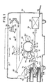
- Fig. 1 is a side elevation view showing the general mechanical construction and arrangement of a preferred embodiment of an image duplicating apparatus according to the present invention;
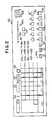
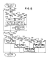
- Fig. 2 is a plan view schematically showing the general configuration of the control panel forming part of the image duplicating apparatus illustrated in Fig. 1;
- Fig. 3 is a diagram schematically showing the arrangement of a control circuit which may be incorporated in the image duplicating apparatus embodying the present invention;
- Fig. 4 is a plan view showing, to an enlarged scale, the arrangement of the various switch areas provided in the touch panel section which forms part of the control panel illustrated in Fig. 2;
- Fig. 5 is a plan view showing the arrangement of switch strips which form the individual switch areas of the touch panel section illustrated in Fig. 4;
- Fig. 6 is a side elevation view of the switch areas forming each of the columns of switch areas in the touch panel section illustrated in Fig. 5;
- Fig. 7 is a view similar to Fig. 4 but shows the arrangement of the indicators respectively associated with the switch areas in the touch panel section illustrated in Fig. 4;
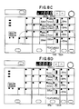
- Figs. 8A to 8D are plan views showing various conditions of the touch panel section as produced when different menue switches and switch areas of the touch panel section are depressed;
- Fig. 9 is a flowchart showing an example of the main routine program to be executed by a master microprocessor unit included in the control circuit illustrated in Fig. 3;
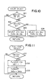
- Fig. 10 is a flowchart showing a color select subroutine program included in the main routine program illustrated in Fig. 9;
- Fig. 11 is a flowchart showing a full-size copy mode select subroutine program included in the main routine program illustrated in Fig. 9;
- Fig. 12 is a flowchart showing a zoomed magnification ratio select mode subroutine program included in the main routine program illustrated in Fig. 9;
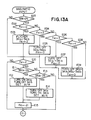
- Figs. 13A, 13B and 13C are flowcharts showing a zoomed magnification ratio input mode select subroutine program included in the main routine program illustrated in Fig. 9;
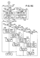
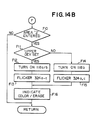
- Figs. 14A and 14B are flowcharts showing a copy-area editing subroutine program included in the main routine program illustrated in Fig. 9; and
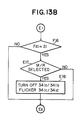
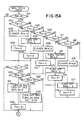
- Figs. 15A and 15B are flowcharts showing a modification of the zoomed magnification ratio input mode select subroutine program illustrated in Figs. 13A to 13C.
- As shown in Fig. 1, an image duplicating apparatus (hereinafter referred to simply as copying apparatus) embodying the present invention comprises a
housing 20 having an upper panel portion formed in part by a transparent document table 22. A sheet of document (not shown) bearing images to be reproduced is to be placed on this document table 22. - During duplication operation of the apparatus, the document sheet placed on the document table 22 is optically scanned by illumination with light from an
optical scanning system 24. A resultant beam of light carrying information representative of the images on the scanned document sheet is directed to animage reproduction system 26. The images carried by the light beam are thus provisionally recorded in the form of latent images, which are then developed into visible toner images through an electrophotographic process performed by theimage reproduction system 26. The visible toner images are transferred to any record medium such as typically a copying sheet transported by a copysheet feed mechanism 28 and the copy sheet now carrying the reproduced images is withdrawn out of the apparatus by means of an image-fixing andsheet discharge system 30. - The
optical scanning system 24 is of the slit exposure type and comprises anexposure lamp 32 from which a beam of light is incident on and reflected from the lower face of the document sheet on the table 22. The light reflected from the document sheet is incident onto anobject mirror 34 and is redirected rearwardly therefrom. Thelamp 32 andobject mirror 34 are carried on a common movable support member and, in combination, implement adocument scanner 36 in the image duplicating apparatus embodying the present invention. Thedocument scanner 36 is movable forwardly along the document table 22 as indicated by arrow a and backwardly as indicated by arrow b and has a predetermined home position with respect to the document table 22. The light reflected from theobject mirror 34 is re-directed toward amirror 38, which further re-directs the light downwardly toward anothermirror 40. Themirrors document scanner 36 and such amirror pair 38/40 are operatively coupled to common drive means comprising a scanner drive motor (MS) implemented by a d.c. reversible motor so that the former is driven to travel at a speed doubling the speed of movement of the latter. - From the
mirror 40, the light travels forwardly along the document table 22 and passes through an image magnification/reduction lens unit 42 to a projectingmirror 46. Thelens unit 42 is movable along the document table 22 independently of thedocument scanner 36 andmirror pair 38/40 with respect to the table 22. Thelens unit 42 is thus operatively coupled to drive means comprising a lens drive motor 48 (ML) which may be implemented by a d.c. stepper motor. From the projectingmirror 46, light is reflected toward theimage reproducing system 26. The projectingmirror 46 is herein assumed to be fixedly held with respect to thehousing 20 but, where desired, may be arranged to be movable and/or rockable with respect to thehousing 20. - The
image reproducing system 26 of the apparatus comprises a cylindricalimage transfer drum 50 having a photoconductive peripheral surface. The light reflected downwardly from the projectingmirror 52 is projected onto the peripheral surface of thisimage transfer drum 50. Thedrum 50 is rotatable about its center axis in a direction indicated by arrow c and is driven for rotation at a fixed peripheral speed by means of a main drive motor (not shown) of the apparatus which may be provided independently of the scanner and lens drive motors. Movement of thelens unit 42 in either direction with respect to themirror 46 results in a change in the position of theunit 42 with respect to the peripheral surface of thedrum 50 and accordingly in a change in the magnification/reduction ratio (hereinafter referred to simply as magnification ratio) of the images to be reproduced. Theimage reproducing system 26 further comprises amain charger 52 to sensitize the photoconductive peripheral surface of theimage transfer drum 50. Posterior to the path of light from themirror 52 to thedrum 50 is located an image developing stage 54 which is herein shown as including two, upper and lower developingunits unit 54a and black-colored toner particles stored in the lower developingunit 54b. - In the image developing stage 54 is further provided a drive motor (MD) by means of which the rotatable members forming part of each of the developing
units image transfer drum 50 from a selected one of the developingunits image transfer charger 56 which is operative to charge the copy sheet so that the toner images formed on thedrum 50 are transferred to the copy sheet. The copy sheet thus having the toner images carried thereon is cleared of charges by aseparation charger 58 which is located posterior to thetransfer charger 56. There is further provided a drum cleaner unit 60 which removes any residual toner particles from the peripheral surface of thedrum 50. Posterior to this cleaner unit 60 in turn is located a charge eraser lamp 62 which irradiates the cleaned peripheral surface of thedrum 50 to eliminate the charges which may be left thereon. - The copy-
sheet feed mechanism 28 of the copying apparatus is provided in conjunction with first and second copy-sheet supply cassettes 64a and 64b detachably fitted to thehousing 20 and which respectively have encased therein stocks of copy sheets of different sizes. The copy-sheet feed mechanism 28 per se comprises first and second copy-sheet feed rollers cassettes 64a and 64b, respectively. Each of theserollers cassettes 64a and 64b. A copying sheet picked up from the first copy-sheet supply cassette 64a by means of the first copy-sheet feed roller 66 or from the second copy-sheet supply cassette 64b by means of the second copy-sheet feed roller 68 is passed through a pair ofguide rollers 70 toward theimage transfer drum 50. There may be further provided a manual copy-sheet feed slot 72 in thehousing 20 so that a copying sheet may be manually inserted into thehousing 20 through thisslot 72 and transported toward thedrum 50 through a pair ofguide rollers 74 and by way of theguide rollers 70. - Immediately posterior to the developing stage 54 is provided a pair of timing
rollers 76. A copying sheet which has been transported toward theimage transfer drum 50 through thesecond guide rollers 78 or through thesecond guide rollers 80 is brought into contact with the peripheral surface of thedrum 50 past these timingrollers 76. The timingrollers 76 are driven for rotation at a timing synchronized with the movement of thedocument scanner 36 so that the copying sheet is correctly transferred to thedrum 50. The timingrollers 76 are further operative to rectify the direction of the copying sheet to be fed to the peripheral surface of thedrum 50. Each of the copy-sheet feed rollers 60 and 62 and each of the guide roller pairs 70 and 74 andtiming roller pair 76 are driven from a main drive motor (MD) of the apparatus by means of respectively associated clutches or other forms of actuators (not shown). - A copy-sheet
transport belt assembly 78 is positioned posterior to the area where the copy sheet is to be separated from theimage transfer drum 50. The copy sheet separated from thedrum 50 is thus conveyed rearwardly through thebelt assembly 78 to animage fixing assembly 80 provided at the rear of thebelt assembly 78. The toner particles carried on the copy sheet are thus thermally fused and the toner images fixed on the copy sheet by means of thisimage fixing assembly 80. The copy sheet released from theimage fixing assembly 80 is withdrawn from the apparatus through a copy-sheet discharge tray 82 attached to thehousing 20 through a slot provided in the rear panel portion of thehousing 20. The copying apparatus embodying the present invention has capabilities to reproduce images within an edited mode within a specified area or areas of a copying sheet. Such an edited mode of operation is performed with use of a selectivecharge eraser unit 84 located posterior to themain charger 52 and anterior to the developing stage 54. - The apparatus embodying the present invention further comprises various sensors and detectors which include a
home position sensor 86 and ascan timing sensor 88 located in conjunction with thedocument scanner 36. Thehome position sensor 86 produces a home position signal (SHP) of a logic "1" bit in the presence of thedocument scanner 36 in the home position thereof. Thescan timing sensor 88 produces an output signal as thescanner 36 is driven for movement over a predetermined distance from its home position with respect to the document table 22. Also provided is a sensor (not shown) for detecting the position of thelens unit 22 with respect to theimage transfer drum 50. - The sensors and detectors provided in the apparatus embodying the present invention further comprise cassette and copy-sheet size detector switches 90a and 92a associated with the first copy-
sheet supply cassette 64a and cassette and copy-sheet size detector switches 90b and 92b associated with the second copy-sheet supply cassette 64b. The cassette detector switches 90a and 90b are responsive to the presence of the first and second copy-sheet supply cassettes 64a and 64b, respectively, and the copy-sheet size detector switches 92a and 92b are responsive to the sizes of copying sheets stored in the first and second copy-sheet supply cassettes 64a and 64b, respectively. There are further provided acolor sensor 94 arranged in conjunction with the upper developingunit 54a to discriminate the type of the developingunit 54a and accordingly the color of the toner stored in the developingunit 54a. It is herein assumed by way of example that there are available three detachable developing units respectively for storing black, red (or magenta) and yellow toners, of which the black toner is stored in the lower developingstage 54b. - Fig. 2 shows the general configuration of a
control panel 100 which forms part of the apparatus embodying the present invention. Thecontrol panel 100 comprises aprint start switch 102 to enable the apparatus to start duplicating operation and a set ofnumerical switches 104 allocated to numerals l, 2, ... and 0, respectively, and used to enter a selected quantity of copy sheets to be printed. The quantity of copy sheets thus entered from thenumerical switches 104 is displayed on a numericaldata display window 106 and can be cleared from a clear/stop switch 108 (C/S) which may be used also for cancelling the instruction once entered from theprint start switch 102. During printing of a preset quantity of copy sheets for a given document sheet, another document sheet may be duplicated in an interrupt mode entered at an interrupt request switch 110 (IR). Thenumerical switches 104 are to be used not only for entering a selected quantity of copy sheets to be printed but for entering numerical data representative of the coordinates to define a desired edited copy/erase area to be specified during an edited copying mode of operation. The numerical data thus entered from theswitches 102 are also displayed on the numerical data displaywindow 106. - The size of copy sheets to be used can be manually selected at a copy-sheet size select switch 112 (SZ) from among a predetermined number of sizes available. The selected size of copy sheets is displayed by any of copy-
sheet size indicators 112a to 112d which are herein assumed to be respectively allocated to the standardized paper sizes A3, B4, A4 and B5 by way of example. The copy-sheet sizeselect switch 112 is, in effect, operative to select one of the copy-sheet supply cassettes 64a and 64b currently installed on the apparatus shown in Fig. 1. On thecontrol panel 100 are further provided a full-size ratio select switch 114 (1/1) for selecting the full-size ratio for copying, theswitch 114 having an associatedindicator 114a. Further provided on thecontrol panel 100 are print density increment and decrement switches 116 with respectively associated indicators 116a to permit manual selection of a desired print density for the copy sheets to be printed. The print density is stepwise incremented with one of theswitches 116 depressed or decremented with the other of theswitches 116 depressed. Furthermore, the color of the imaged to be printed can be selected from among different available colors at a color select switch 118 (CL) having associatedcolor indicators select switch 118 is in effect operative to select one or two of the developingunits control panel 100 are further providedzoom switches 120 for continuously varying the coordinate values or magnification ratio entered for edited mode of copying operation. The numerical data continuously selected by theswitches 120 are displayed on a magnificationratio display window 122 for visual assistance to the operator. - The
control panel 100 of the apparatus embodying the present invention further comprises atouch panel section 124 arranged with various switches and indicators as schematically illustrated in Fig. 2. The details of such atouch panel section 124 will be described hereinafter. - Fig. 3 shows the general arrangement of a control circuit which may be used to achieve various modes and conditions of copying operation in the apparatus embodying the present invention. The control circuit comprises first and
second microprocessors 200 and 202 (hereinafter referred to as CPU1, CPU2 and CPU3, respectively). TheCPU1 200 and CPU2 202 have interrupt and data input and output ports connected together through abidirectional bus 204. TheCPU1 200 is mainly operative to control the operation of theimage reproducing system 26 andpaper feed mechanism 28 while theCPU2 202 is predominant over the operation of theoptical scanning system 24. The CPU2 is mainly operative to control the operation of the opticaldocument scanning system 24. - The
first CPU1 200 has input terminals connected through adecoder 206 to inputexpander circuits expander circuits 208 to 214 to various switch elements (herein collectively represented by numeral 100) including those on thecontrol panel 100. Data entered from such switch elements are stored into a random-access memory (RAM) 216 which is connected to the CPU1 through a bidirectional bus and which has a backuppower supply source 220. TheCPUl 200 further has output terminals connected through adecoder 222 tooutput expander circuits expander circuits 224 to 228 to the drivers and actuators (herein collectively represented by numeral 230) for the main drive motor, the motor incorporated in the developing stage 54, the clutches for the copy sheet feed and guiderollers rollers 76, thechargers CPU1 200 further has output terminals connected through adecoder 232 to the various indicators and display units (herein collectively represented by numeral 234) provided on thecontrol panel 100 on thecontrol panel 100. - The
second CPU2 202 has input terminals connected to thehome position sensor 86 and scantiming sensor 88 provided in association with theoptical scanning system 24 and is operative to control the driver circuits for the scanner drive motor MS and the stepper motor ML for themagnification lens unit 42. TheCPU2 202 is thus responsive to signals from the home position and scan timingsensors optical scanning system 24 under the control of thefirst CPU1 200 through thebus 204. - The
first CPU1 200 may be further connected to an exposure control circuit 236 which controls the intensity of illumination by theexposure lamp 32. - Fig. 4 shows to an enlarged scale the arrangement of the
touch panel section 124 of thecontrol panel 100. Thetouch panel section 124 comprises first, second, third, fourth andfifth subsections subsections 300 to 308 is assigned to a group of different modes of operation any of which can be selected from the menu select switch included in the particular subsection. - The
first subsection 300 is provided for the selection of an edited copy mode which is selected from a menu select switch implemented by an edited copy modeselect switch 310 to enable entry of various instructions and data for an edited mode of copying operation. When this edited copy modeselect switch 310 is depressed to select the edited copying mode of operation, two of theindicators 118a associated with the colorselect switch 118, viz., the indicators respectively allocated to the two different print colors available by the upper and lower developingunits units - In association with the edited copy mode
select switch 310 are arranged first to fourth indicators which consist of twox-coordinate indicators 312a and 312b and two y-coordinateindicators touch panel section 124 anarea display screen 314 on which a desired edited copy/erase area R to be printed or erased is to be visually indicated. An xy-coordinate system is thus taken into account on thisarea display screen 314 as having an axis of abscissa corresponding to the direction of circumferential direction of thedrum 50 and an axis of ordinate corresponding to the axial direction of thedrum 50, with an origin at the right lower corner of thescreen 314. The desired edited copy/erase area R can thus be defined by the combination of x-coordinates X₁ and X₂ and y-coordinates Y₁ and Y₂ which may be designated from any of the numerical switches 104. - In the copying apparatus according to the present invention, it is assumed that there may be specified and displayed on the
area display screen 314 two different edited copy/erase areas of a copying sheet. These two edited copy areas will be herein referred to respectively as "edited copy/erasearea 1" or simply as "area 1" and "edited copy/erasearea 2" or simply as "area 2". The remaining area of the copying sheet surrounding theseareas area display screen 314 is thus assumed to be representative of one of such two edited copy/eraseareas areas areas indicators areas indicator 320. - The coordinate data for each of the desired edited copy/erase
areas numerical switches 104 and/or the zoom switches 120 and numerical data displaywindow 106 and entered with a dataenter switch area 322 depressed. On the other hand, the selection between the two colors for each of the three areas can be entered through a blackselect switch area 324a and acolor switch area 324b. Theblack switch area 324a is used for selecting black as the print color in which the images within the desired edited copy/erasearea color switch area 324b is used for selecting another print color such as red (or yellow) as the color in which the images within the desired edited copy/erasearea switch area 324c which may be used where it is desired to erase the images within one or both of the desired edited copy/erasearea areas switch area 324d may be depressed. - The
charge eraser unit 84 provided in the apparatus shown in Fig. 1 is composed of a number of light emitter elements arranged in a single linear array. The linear array of the light emitter elements is positioned close to the peripheral surface of theimage transfer drum 50 and extends in parallel to the axis of rotation of thedrum 50. When the light emitter elements of such ancharge eraser unit 84 are activated to illuminate selectively with thedrum 50 being driven for rotation, the charges on those small areas of the drum surface which are illuminated by the selected light emitter elements are caused to disappear. Accordingly, no latent images can be produced on the particular areas of the drum surface when the drum surface is irradiated with an information carrying beam. When some particular ones of the light emitter elements are activated from one specified time to another, the charges are caused to dissipate on the area of the drum surface as defined by the four coordinate points given by the x-coordinates X₁ and X₂ and the y-coordinates Y₁ and Y₂. There can thus be produced no latent images within this area when thedrum 50 is illuminated with an information carrying beam incident on the drum surface. The area is displayed as the edited copy/erase area R on thedisplay screen 316 shown in Fig. 4. - The
second subsection 302 of thetouch panel section 124 is provided for the selection of a feature "1" mode which is selected from a menu select switch implemented by a feature "1" modeselect switch 326. The feature "1" modeselect switch 326 is associated with a first column of fourswitch areas 328a to 328d and a second column of four switch areas 330a to 330d located to the left of theswitch areas 328a to 328d, respectively. - The
third subsection 304 of thetouch panel section 124 is provided for the selection of a feature "2" mode which is selected from a menu select switch implemented by a feature "2" modeselect switch 332. The feature "2" modeselect switch 332 is associated with a first column of fourswitch areas 334a to 334d and a second column of fourswitch areas 336a to 336d located to the left of theswitch areas 334a to 334d, respectively. By way of example, theswitch areas switch area 334c may be used for the selection of a frame erase mode, and theswitch area 334d may be used for the selection of a punch-hole erase mode. Theswitch areas switch switch 334c Thus, the mode or condition achievable by any of theswitches 336a to 336c of the second column is subsidiary to the mode or condition selected by any of theswitches 334a to 334c of the first column. It may be noted that theswitch area 334d for the selection of a punch-hole erase mode has no mode or condition subsidiary to the punch-hole erase mode selected by theparticular switch 334d. - The
fourth subsection 306 of thetouch panel section 124 is provided for the selection of a zoomed magnification ratio input mode which is selected from a menu select switch implemented by a zoomed magnification ratio input modeselect switch 338. The zoomed magnification ratio input modeselect switch 338 is associated with a column of fourswitch areas 340a to 340d. By way of example, theswitch area 340a may be used for the selection of a mode in which a desired magnification ratio is entered from the numerical switches 104. Theswitch area 340b may be used for the selection of a mode for calculating a magnification ratio on the basis of any desired numerical data. Theswitch area 340c may be used for the selection of a mode for establishing a desired magnification ratio to be used only for a single cycle of copying operation. Theswitch area 340d may be used for the selection of a mode in which the desired magnification ratio is to be stored into any one of the magnification memory areas (not shown) provided in theCPU1 200. - The
fifth subsection 308 of thetouch panel section 124 is provided for the selection of a zoomed magnification ratio select mode which is selected from a menu select switch implemented by a zoomed magnification ratio select modeselect switch 342. The zoomed magnification ratio select modeselect switch 342 is associated with a column of four switch areas 344a to 344d which may be used for the selection of the magnification memory areas provided in theCPU1 200. - To the right of the
touch panel section 124 are provided user's memorandum areas 346 which may be labelled with any marks, symbols or other indications desired by the user. Indicated at 348 is a total value read switch. - In the
touch panel section 124 on thecontrol panel 100 of the apparatus embodying the present invention, the respective menu switches 310, 326, 332, 338 and 342 of thesubsections switch areas fifth switch strips first strip 350a form theswitch areas subsections second switch strip 350b form theswitch areas 324b 328b, 330b, 334b, 336b, 340b and 344b arranged in a second row of thesubsections third switch strip 350c form theswitch areas subsections third switch strip 350c further forms theswitch areas 322 of thesubsection 300 as shown. Thefourth switch strip 350d form theswitch areas subsections - Fig. 6 is a side elevation view of the switch areas of the touch panel section illustrated in Fig. 5 and may by way of example show the switch areas 344a to 344d forming the column of the
fifth subsection 308 of thetouch panel section 124 shown in Fig. 4. As will be seen from Fig. 6, thetouch panel section 124 is provided on a printedcircuit board 352 and compriseslight emitter elements 354 located in the individual switch areas 344a to 344d, respectively, forming the column of thesubsection 308 of thetouch panel section 124. Over theselight emitter elements 354 is positioned afilm 356 on which are printed the marks, symbols or other indications representative of the modes or conditions allocated to the individual switch areas 344a to 344d, respectively, of thesubsection 308. On thefilm 356 are provided portions of theswitch strips 350a to 350d, the portions of theswitch strips 350a to 350d forming the individual switch areas 344a to 344d, respectively, of thesubsection 308. Each of theswitch strips 350a to 350d is herein assumed to be formed of a flexible transparent layer. On the other hand, each of the menu switches such as the zoomed magnification ratio select modeselect switch 342 herein shown is provided in the form of an ordinary push-button switch element having a keytop member 358. - The individual switch areas of the
touch panel section 124 thus arranged have respectively associated indicators each of which is to be turned on to flicker or illuminate when the associated switch area is manually depressed. Such indicators are formed by thelight emitter elements 354 provided in the switch configuration shown in Fig. 6 and each implemented by a light emitting diode (LED). The indicators are visually accessible through apertures formed in thefilm 356 bearing the marks, symbols or other indications and are herein shown in the forms of solid spots, as indicated in Fig. 7 at 323, 325a to 325d, 329a to 329c, 331a to 331c, 335a to 335d, 337a to 337c, 341a to 341d, and 345a to 345d. - At an initial stage after the apparatus has been switched in, only the
print start switch 104 and the magnificationratio display window 122 are turned on to illuminate in green on thecontrol panel 100. Theprint start switch 104 thus illuminating in green is in a condition allowing the operator to start copying operation through theswitch 104. The operator of the apparatus may then depress the feature "2" modeselect switch 332 in thetouch panel section 124. With the feature "2" modeselect switch 332 depressed, theindicators switch areas third subsection 304 are turned on to flicker each as indicated by a hollow spot with radials in Fig. 8A. Simultaneously when theindicators 335a to 335b are thus turned on to flicker, theprint start switch 104 is conditioned to illuminate in red. Theprint start switch 104 thus illuminating in red is in a condition prohibiting the operator from starting copying operation through theswitch 104. The operator of the apparatus may then depress thethird switch area 334c assigned to the frame erase mode. For this purpose, the operator may depress any one of theswitch areas third switch strip 350c. Thethird switch area 334c or any one of these switch areas being thus depressed, theindicators other switch areas third subsection 304 are caused to turn off and, in turn, theindicators switch areas subsection 304 are turned on to flicker as indicated in Fig. 8B. The operator of the apparatus may now depress thesecond switch area 336c assigned to the 10mm margin or frame width. In this instance, the same result will be achieved if the operator depresses any one of theswitch areas second switch strip 350b. Thesecond switch area 336b or any one of these switch areas being thus depressed, theindicators other switch areas subsection 304 are caused to turn off as indi′ated in Fig. 8C. Entry of instructions through thetouch panel section 124 being thus complete, theprint start switch 104 is for a second time conditioned to illuminate in green. - If the
switch area 334d for the selection of the punchhole erase mode is depressed after the feature "2" modeselect switch 304 is depressed, then only theindicator 335b associated with theparticular switch area 334d is turned on to flicker with theindicators switch areas subsection 304 turned off, as indicated in Fig. 8D. This is because of the fact that theswitch area 334d for the selection of the punchhole erase mode has no mode or condition subsidiary to the mode selected by theparticular switch 334d. Thus, entry of instructions through thetouch panel section 124 is now complete so that theprint start switch 104 is for a second time conditioned to illuminate in green allowing the operator to start copying operation. - As will have been understood from the foregoing description that a total of (m x n) number of switch areas are available and accordingly the user of the apparatus is allowed to select one out of a total of (m x n) number of modes or conditions through provision of an m number of menu switches and an n number of switch strips. If, in addition, there are two or more sets of switch areas provided in association with one of the menu switches so that the modes or conditions dictated by one set of switch areas are subsidiary to those dictated by another set of switch areas, more than (m x n) number of modes or conditions are available for selection through provision of the m number of menu switches and n number of switch strips.
- Fig. 9 shows the main routine program to be executed by the first or
master CPU1 200 provided in the control circuit described with reference to Fig. 3. The routine program starts with the copying apparatus switched in and initializes themaster CPU1 200 at a step A01 so that all the copying conditions and modes of operation to be controlled by means of theCPU1 200 are selected in accordance with prescribed "default" rules. An internal timer of the system is then initiated at a step A02 to count the time interval predetermined for a single complete iteration through the routine program. - The
master CPU1 200 may then execute a color select subroutine program A03 by which one or both of the developingunits control panel 100. The details of the color select subroutine program A03 will be hereinafter described with reference to Fig. 10. The color select subroutine program A03 may be followed by a fullsize copy mode select subroutine program A04 to establish a copying mode of operation using a magnification ratio of 1:1. The details of this full-size copy mode select subroutine program A04 will be hereinafter described with reference to Fig. 11. - The master CPU1 408 may thereafter execute a zoomed magnification ratio select mode select subroutine program A05 responsive to depression of the zoomed magnification ratio select mode
select switch 342 of thesubsection 308 depressed in thetouch panel section 124. The details of this zoomed magnification ratio select mode select subroutine program A05 will be hereinafter described with reference to Fig. 12. The zoomed magnification ratio select mode select subroutine program A05 may be followed by a zoomed magnification ratio input mode select subroutine program A06 responsive to depression of the zoomed magnification ratio input modeselect switch 338 of thesubsection 306 depressed in thetouch panel section 124. The details of this zoomed magnification ratio input mode select subroutine program A06 will be hereinafter described with reference to Figs. 13A, 13B and 13C or to Figs. 15A and 15B which show a modification of the subroutine program illustrated in Figs. 13A to 13C. - The
master CPU1 200 may then execute a copy-area editing subroutine program A07 to establish an edited mode of copying operation. The details of the copy-area editing subroutine program A07 will be hereinafter described with reference to Figs. 14A and 14B. Subsequently to the copy-area editing subroutine program A07, themaster CPU1 200 may execute a subroutine program A08 to process various instruction and data signals supplied from thecontrol panel 100 while generating instructions to update the numerical data on thedisplay window 106 of thecontrol panel 100. Thereafter, themaster CPU1 200 may further execute a copying control subroutine program A09 predominant over the copying operation to be performed by the apparatus in accordance with the various instruction and data signals supplied from thecontrol panel 100. The master CPU1 408 may further execute an inter-CPU communication data updating subroutine program A10 by which the data received by theCPU1 200 may be transferred to an internal memory unit incorporated within the CPU1 and the data thus processed in the internal memory unit is transferred to therandom access memory 210 for transmission to the other or slave microprocessors such as thesecond CPU2 202. Upon lapse of the predetermined time interval as detected at a step All after the internal timer of the system has been initiated at the step A02, the system reverts to the step A02 and recycles the subroutine programs A03 to A10. - Description will be hereinafter made with reference to Fig. 10 to Figs. 15A to 15C in regard to the various subroutine programs thus included in the main routine program to be executed by the
master CPU1 200. - Fig. 10 is a flowchart showing the details of the color select subroutine program A03 included in the main routine program illustrated in Fig. 9. The color select subroutine program A03 starts with a decision step B01 at which it is queried whether or not there is present a signal produced with the color
select switch 118 depressed on thecontrol panel 100. In the presence of such a signal, it is further confirmed at a step B02 whether or not the upper developingunit 54a had been selected until the signal was produced with theswitch 118 depressed. If the answer for this step B02 is given in the affirmative, an instruction signal is issued at a step B03 so that the lower developingunit 54b storing the black-colored toner particles is selected for use and accordingly theindicator 118a assumed to be allocated to the black print color is turned on to illuminate. If, conversely, the answer for the step B02 is given in the negative, an instruction signal is issued at a step B04 so that the upper developingunit 54a storing the red-colored toner particles is selected for use and accordingly theindicator 118a assumed to be allocated to the red print color is turned on to illuminate. - Fig. 11 shows the details of the full-size copy mode select subroutine program A04 included in the main routine program illustrated in Fig. 9. The full-size copy mode select subroutine program A04 starts with a decision step C01 at which it is queried whether or not there is present a signal produced with the full-size ratio
select switch 114 depressed on thecontrol panel 100 for selecting the full-size ratio for copying. In the presence of such a signal, an instruction signal is issued at a step C02 to turn on theindicator 114a associated with the full-size ratioselect switch 114 and to drive thelens unit 42 to move to a position providing a one-to-one magnification ratio for copying. The step C02 is followed by a step C03 at which an instruction signal is issued to turn off all theindicators 345a to 345d respectively associated with the switch areas 344a to 344d of thefifth subsection 308 of thetouch panel section 124. - Fig. 12 shows a zoomed magnification ratio select mode select subroutine program A05 also included in the main routine program illustrated in Fig. 9. The zoomed magnification ratio select mode select subroutine program A05 starts with a decision step D01 at which it is queried whether or not there is present a signal produced with the zoomed magnification ratio select mode
select switch 342 depressed in thetouch panel section 124. In the presence of such a signal, it is further tested at a step D02 whether or not a status flag FZS is of a logic "0" state. If it is found that the status flag FZS is of logic "0" state, the status flag FZS is shifted to a logic "1" state at a step D03. The step D03 is followed by a step D04 at which an instruction signal is issued so that all theindicators 345a to 345d respectively associated with the switch areas 344a to 344d are turned on to flicker in thefifth subsection 308 of thetouch panel section 124. If it is found at the step D02 that the status flag FZS is of logic "1" state, then the status flag FZS is shifted to logic "0" state at a step D05. The step D05 is followed by a step D06 at which an instruction signal is issued so that all theindicators 345a to 345d respectively associated with the switch areas 344a to 344d are turned off in thefifth subsection 308 of thetouch panel section 124. Subsequently to the step D07, a step D08 is followed to issue an instruction signal turn on theindicator 114a associated with the full-size ratioselect switch 114 and to drive thelens unit 42 to move to a position providing a one-to-one magnification ratio for copying. - If it is found at the step D01 that there is no signal produced with the zoomed magnification ratio select mode
select switch 342 depressed or subsequently to the step D04 or step D08, it is further tested at a step D09 whether or not the status flag FZS is of logic "1" state. If it is found that the status flag FZS is of the logic "1" state, it is queried at a step D10 whether or not there is present a signal produced with thefirst switch strip 350a depressed in thetouch panel section 124. In the presence of such a signal, the step D10 is followed by a step D11 at which the status flag FZS is shifted to logic "0" state and an instruction signal is issued so that only theindicator 345a associated with the switch area 344a is turned on to flicker with all theother indicators 345b to 345d for the switch areas 344b to 344d turned off in thefifth subsection 308 of thetouch panel section 124. At this step D11 is further issued an instruction signal to drive thelens unit 42 to move to a position providing a first predetermined magnification ratio memorized in the magnification memory area selected from the switch area 344a. - If it is found at the step D09 that there is no signal produced with the
first switch strip 350a depressed in thetouch panel section 124, it is further tested at a step D12 whether or not there is present a signal produced with thesecond switch strip 350b depressed in thetouch panel section 124. In the presence of such a signal, the step D12 is followed by a step D13 at which the status flag FZS is shifted to logic "0" state and an instruction signal is issued so that only theindicator 345b associated with the switch area 344b is turned on to flicker with all theother indicators switch areas subsection 308. At this step D13 is further issued an instruction signal to drive thelens unit 42 to move to a position providing a second predetermined magnification ratio memorized in the magnification memory area selected from the switch area 344b. - If it is found at the step D12 that there is no signal produced with the
second switch strip 350b depressed in thetouch panel section 124, it is further tested at a step D14 whether or not there is present a signal produced with thethird switch strip 350c depressed in thetouch panel section 124. In the presence of such a signal, the step D14 is followed by a step D15 at which the status flag FZS is shifted to logic "0" state and an instruction signal is issued so that only theindicator 345c associated with theswitch area 344c is turned on to flicker with all theother indicators switch areas 344a, 344b and 344d turned off in thesubsection 308. At this step D15 is further issued an instruction signal to drive thelens unit 42 to move to a position providing a third predetermined magnification ratio memorized in the magnification memory area selected from theswitch area 344c. - If it is found at the step D14 that there is no signal produced with the
third switch strip 350c depressed in thetouch panel section 124, it is further tested at a step D16 whether or not there is present a signal produced with thefourth switch strip 350d depressed in thetouch panel section 124. In the presence of such a signal, the step D16 is followed by a step D17 at which the status flag FZS is shifted to logic "0" state and an instruction signal is issued so that only theindicator 345d associated with theswitch area 344d is turned on to flicker with theindicators 345a to 345c for all the other switch areas 344a to 344c turned off in thesubsection 308. At this step D17 is further issued an instruction signal to drive thelens unit 42 to move to a position providing a fourth predetermined magnification ratio memorized in the magnification memory area selected from theswitch area 344d. If it is found at the step D16 that there is no signal produced with thefourth switch strip 350d depressed in thetouch panel section 124 or subsequently to any of the steps D11, D13, D15 and D17, the system recycles the subroutine program. - Figs. 13A, 13B and 13C show the zoomed magnification ratio input mode select subroutine program A06 further included in the main routine program illustrated in Fig. 9. The zoomed magnification ratio input mode select subroutine program A06 starts with a decision step E01 at which it is queried whether or not there is present a signal produced with the zoomed magnification ratio input mode
select switch 338 depressed in thetouch panel section 124. In the presence of such a signal, it is further tested at a step E02 whether or not a status flag FZI is of a "0" state. If it is found that the status flag FZI is of the "0" state, the step E02 is followed by a step E03 at which the status flag FZI is shifted to a "2" state and an instruction signal is issued so that theindicators switch areas fourth subsection 306 of thetouch panel section 124. Under these conditions, a magnification ratio is entered either from thenumerical switches 104 or through calculation. If it is found at the step E02 that the status flag FZI is not of the "0" state, it is tested at a step E04 whether or not the status flag FZI is of the "2" state. If it is found that the status flag FZI is of the "2" state, the step E04 is followed by a step E05 at which the status flag FZI is shifted to the "0" state and an instruction signal is issued so that theindicators switch areas subsection 306. - If it is found at the step E04 that the status flag FZI is not of the "2" state, it is tested at a step E06 whether or not the status flag FZI is of a "3" state. If it is found that the status flag FZI is of the "3" state, the step E06 is followed by a step E07 at which the status flag FZI is shifted to the "0" state and an instruction signal is issued so that the
indicators 341a to 341d respectively associated with all theswitch areas 340a to 340d in thesubsection 306 are turned off. If it is found at the step E06 that the status flag FZI is not of the "3" state, it is tested at a step E08 whether or not the status flag FZI is of a "4" state. If it is found that the status flag FZI is of the "4" state, the step E08 is followed by a step E09 at which the status flag FZI is shifted to the "0" state and an instruction signal is issued so that theindicators 341a to 341d respectively associated with all theswitch areas 340a to 340d in thesubsection 306 and, in addition, theindicators 345a to 345d for all the switch areas 344a to 344d in thefifth subsection 308 are turned off. - If it is found at the step E08 that the status flag FZI is not of the "4" state or subsequently to any of the steps E03, E05, E07 and E09, it is tested at a step E10 whether or not the status flag FZI is of the "2" state. If it is found that the status fla FZI is of the "2" state, the step E10 is followed by a step E11 at which it is queried whether or not there is present a signal produced with the
first switch strip 350a depressed in thetouch panel section 124. In the presence of such a signal, an instruction signal is issued at a step E12 so that theindicator 341a associated with theswitch area 340a is turned on to flicker and theindicator 341b for theswitch area 340b turned off in thefourth subsection 306 of thetouch panel section 124. Under these conditions, a magnification ratio is entered from the numerical switches 104. If it is found at the step E11 that there is no signal produced with thefirst switch strip 350a depressed, it is queried at a step E13 whether or not there is present a signal produced with thesecond switch strip 350b depressed in thetouch panel section 124. In the presence of such a signal, an instruction signal is issued at a step E14 so that theindicator 341a associated with theswitch area 340a is turned off and theindicator 341b for theswitch area 340b turned on to flicker in thefourth subsection 306 of thetouch panel section 124. Under these conditions, the magnification ratio is entered through calculation. Such calculation may be performed through any switches additionally provided on thecontrol panel 100 or any of the existing switches on thecontrol panel 100. - Subsequently to the step E12 or E14, the status flag FZI is shifted to a "21" state at a step E15, whereupon it is confirmed at a step E16 shown in Fig. 13B whether or not the status flag FZI is of the "21" state. If it is found that the status flag FZI is of the "21" state, it is tested at a step E17 whether or not there currently is a magnification ratio entered either from the numerical switches or through calculation. If the answer for this step E17 is given in the affirmative, the step E17 is followed by a step E18 at which the status flag FZI is shifted to the "3" state and an instruction signal is issued so that only the
indicators switch areas indicators 341c and 341d for theswitch areas fourth subsection 306 of thetouch panel section 124. - Subsequently to the step E18 or if the answer for the step E16 or E17 is given in the negative, it is tested at a step E19 whether or not the status flag FZI is of the "3" state. If it is found that the status flag FZI is of the "3" state, the step E19 is followed by a step E20 at which it is queried whether or not there is present a signal produced with the
third switch strip 350c depressed in thetouch panel section 124. In the presence of such a signal, an instruction signal is issued at a step E21 so that theindicator 341c associated with theswitch area 340c is turned on to flicker and the indicator 341d for theswitch area 340d turned off in thefourth subsection 306 of thetouch panel section 124. Under these conditions, the magnification ratio determined for a single cycle of copying operation is used without being stored into the memory. Such a magnification ratio is, if found necessary, corrected at a step E22 so as to be acceptable for the capabilities of the apparatus and thelens unit 42 is then driven to move to a position to provide the magnification ratio thus corrected. If it is found at the step E20 that there is no signal produced with thethird switch strip 350c depressed, it is queried at a step E23 whether or not there is present a signal produced with thefourth switch strip 350d depressed in thetouch panel section 124. In the presence of such a signal, an instruction signal is issued at a step E24 so that theindicator 341c associated with theswitch area 340c is turned off and the indicator 341d for theswitch area 340d turned on to flicker in thefourth subsection 306 of thetouch panel section 124. The step E24 is followed by a step E25 at which an instruction signal is issued so that theindicators 345a to 345d respectively associated with all the switch areas 344a to 344d are turned on to flicker in thefifth subsection 308 of thetouch panel section 124, requesting that the magnification ratio determined from thenumerical switches 104 or through calculation be stored into the memory area designated by any of the switch areas 344a to 344d in thefifth subsection 308. - Subsequently to the step E22 or E25 or if the answer for the step E19 or E23 is given in the negative, it is tested at a step E26 whether or not the status flag FZI is of the "4" state. If it is found that the status flag FZI is of the "4" state, it is queried at a step E27 whether or not there is present a signal produced with the
first switch strip 350a depressed in thetouch panel section 124. In the presence of such a signal, the step E27 is followed by a step E28 at which an instruction signal is issued so that only theindicator 345a associated with the switch area 344a is turned on to flicker with theindicators 345b to 345d for all the other switch areas 344b to 344d turned off in thefifth subsection 308 of thetouch panel section 124. At this step E28 is further issued an instruction so that the magnification ratio determined is, if found necessary, corrected so as to be acceptable for the capabilities of the apparatus. The step E28 is followed by a step E29 at which an instruction signal is further issued to drive thelens unit 42 for movement to a position providing the magnification ratio thus corrected while memorizing the magnification ratio into the selected memory area and shifting the status flag FZS to the "0" state. - If it is found at the step E27 that there is no signal produced with the
first switch strip 350a depressed in thetouch panel section 124, it is further tested at a step E30 whether or not there is present a signal produced with thesecond switch strip 350b depressed in thetouch panel section 124. In the presence of such a signal, the step E30 is followed by a step E31 at which an instruction signal is issued so that only theindicator 345b associated with the switch area 344b is turned on to flicker with theindicators 345a 345c and 345d for the other switch areas 344a 344c and 344d turned off in thefifth subsection 308 of thetouch panel section 124. At this step E31 is further issued an instruction to correct the magnification ratio determined. The step E31 is followed by a step E32 at which an instruction signal is further issued to drive thelens unit 42 for movement to a position providing the corrected magnification ratio while memorizing the magnification ratio into the selected memory area and shifting the status flag FZS to the "0" state. - If it is found at the step E30 that there is no signal produced with the
second switch strip 350b depressed in thetouch panel section 124, it is further tested at a step E33 whether or not there is present a signal produced with thethird switch strip 350c depressed in thetouch panel section 124. In the presence of such a signal, the step E33 is followed by a step E34 at which an instruction signal is issued so that only theindicator 345c associated with theswitch area 344c is turned on to flicker in thefifth subsection 308 of thetouch panel section 124. At this step E34 is further issued an instruction to correct the magnification ratio determined. The step E34 is followed by a step E35 at which an instruction signal is further issued to drive thelens unit 42 for movement to a position providing the corrected magnification ratio while memorizing the magnification ratio into the selected memory area and shifting the status flag FZS to the "0" state. If it is found at the step E33 that there is no signal produced with thesecond switch strip 350c depressed, it is further tested at a step E36 whether or not there is present a signal produced with thefourth switch strip 350d depressed. In the presence of such a signal, the step E36 is followed by a step E37 at which an instruction signal is issued so that only theindicator 345d associated with theswitch area 344d is turned on to flicker. At this step E37 is further issued an instruction to correct the magnification ratio determined, whereupon an instruction signal is issued at a step E38 to drive thelens unit 42 for movement to a position providing the corrected magnification ratio while memorizing the magnification ratio into the selected memory area and shifting the status flag FZS to the "0" state. If it is found at the step E36 that there is no signal produced with thefourth switch strip 350d depressed in thetouch panel section 124 or subsequently to any of the steps E29, E32, E55 and E38, the system recycles the subroutine program. - Fig. 14 shows the details of the copy-area editing subroutine program A07 further included in the main routine program illustrated in Fig. 9. The copy-area editing subroutine program A07 starts with a decision step F01 at which it is queried whether or not there is a signal produced with the edited copy mode
select switch 310 depressed. In the presence of such a signal, an instruction signal is issued at a step F02 to turn off all theindicators 118a associated with the colorselect switch 118 and enable entry of signals to build up an area in thearea display screen 314. Subsequently to this step F02 or if it is found at the step F01 that an edited mode of copying operation is not currently selected, it is confirmed at a step F03 whether or not entry of the x-coordinates X₁ and X₂ and y-coordinates Y₁ and Y₂ for the desired edited copy/erasearea 1 is complete. If the answer for this step F03 is given in the affirmative, it is further queries at a step F04 whether or not the upper developingunit 54a is installed within the apparatus. If the developingunit 54a is found to be installed in the apparatus, an instruction signal is issued at a step F05 by which theindicators units indicators select switch 324a,area color switch 324b and area eraseswitch 324c are turned on to flicker. If it is found at the step F04 that the upper developingunit 54a is currently not installed within the apparatus, then an instruction signal is issued at a step F07 by which theindicator 118a allocated to the developingunit 54a storing the black colored toner is turned on to flicker. The step F07 is followed by a step F08 by which an instruction signal is further issued so that theindicators select switch 324a and area eraseswitch 324c are turned on to flicker. The operator will then depress any one of theswitches switches 324a 324b and 324c is permitted to illuminate continuously. - Subsequently to the step F09 or if it is found at the step F03 that the entry of the x- and y-coordinates specifying the desired edited copy/erase
area 1 is still incomplete, it is confirmed at a step F10 shown in Fig. 14B whether or not entry of the x-coordinates X₁ and X₂ and y-coordinates Y₁ and Y₂ for the desired edited copy/erasearea 2 is complete. If the answer for this step F10 is given in the affirmative, it is further queries at a step F11 whether or not the upper developingunit 54a is installed within the apparatus. If the developingunit 54a is found to be installed in the apparatus, an instruction signal is issued at a step F12 by which theindicators units indicators select switch 324a,area color switch 324b and area eraseswitch 324c are turned on to flicker. If it is found at the step F11 that the upper developingunit 54a is currently not installed within the apparatus, then an instruction signal is issued at a step F14 by which theindicator 118a allocated to the developingunit 54a storing the black colored toner is turned on to flicker. The step F14 is followed by a step F15 by which an instruction signal is further issued so that theindicators select switch 324a and area eraseswitch 324c are turned on to flicker. The operator will then depress any one of theswitches switches area 1 is still incomplete, the system returns to the step F01. - Figs. 15A and 15B show a modification of the zoomed magnification ratio input mode select subroutine program A06 described with reference to Figs. 13A to 13C. The modified subroutine program herein shown starts with a decision step G01 at which it is queried whether or not there is present a signal produced with the zoomed magnification ratio input mode
select switch 338 depressed in thetouch panel section 124. In the presence of such a signal, it is further tested at a step G02 whether or not the status flag FZI is of a "0" state. If it is found that the status flag FZI is of the "0" state, the step G02 is followed by a step G03 at which an instruction signal is issued so that theindicators switch areas fourth subsection 306 of thetouch panel section 124. At a subsequent step G04, the status fla FZI is shifted to a "2" state so that a magnification ratio may be entered either from thenumerical switches 104 or through calculation. If it is found at the step G02 that the status flag FZI is not of the "0" state, it is tested at a step G05 whether or not the status flag FZI is of the "2" state. If it is found that the status flag FZI is of the "2" state, the step G05 is followed by a step G06 at which an instruction signal is issued so that theindicators switch areas subsection 306. The status fla FZI is shifted to the "0" state at a subsequent step G07. - If it is found at the step G05 that the status flag FZI is not of the "2" state, it is tested at a step G08 whether or not the status flag FZI is of a "21" state. If it is found that the status flag FZI is of the "21" state, the step G08 is followed by a step G07 at which an instruction signal is issued so that the
indicators switch areas subsection 306 are turned on to flicker. The status flag FZI is shifted to the "2" state at a subsequent step G10. If it is found at the step G08 that the status flag FZI is not of the "21" state, it is tested at a step G11 whether or not the status flag FZI is of a "3" state. If it is found that the status flag FZI is of the "3" state, the step G11 is followed by a step G12 at which an instruction signal is issued so that the immediate preceding condition having the status flag FZI of the "21" state is restored and each of theindicators switch areas subsection 306 is turned on or off. At subsequent steps G13 and G14, theindicators 341c and 341d respectively associated with theswitch areas subsection 306 are turned off and the status flag FZI is shifted to the "21" state. - If it is found at the step G11 that the status flag FZI is not of the "3" state, it is tested at a step G15 whether or not the status flag FZI is of a "4" state. If it is found that the status flag FZI is of the "4" state, the step G15 is followed by a step G16 at which an instruction signal is issued so that the
indicators 341c and 341d respectively associated with theswitch areas subsection 306 are turned on to flicker. Subsequently, an instruction signal is issued at a step G17 so that theindicators 345c to 345d respectively associated with all the switch areas 344a to 344d in thefifth subsection 308 are turned off and, further at a subsequent step G18, the status flag FZI is shifted to the "3" state. - If it is found at the step G08 that the status fla FZI is not of the "4" state or subsequently to any of the steps G04, G07, G10, G14 and G18, it is tested at a step G19 whether or not the status flag FZI is of the "2" state. If it is found that the status flag FZI is of the "2" state, the step G19 is followed by a step G20 at which it is queried whether or not there is present a signal produced with the
first switch strip 350a depressed in thetouch panel section 124. In the presence of such a signal, an instruction signal is issued at a step G21 so that theindicator 341a associated with theswitch area 340a is turned on to flicker and theindicator 341b for theswitch area 340b turned off in thefourth subsection 306 of thetouch panel section 124. Under these conditions, a magnification ratio is entered from the numerical switches 104. If it is found at the step G20 that there is no signal produced with thefirst switch strip 350a depressed, it is queried at a step G22 whether or not there is present a signal produced with thesecond switch strip 350b depressed in thetouch panel section 124. In the presence of such a signal, an instruction signal is issued at a step G23 so that theindicator 341a associated with theswitch area 340a is turned off and theindicator 341b for theswitch area 340b turned on to flicker in thefourth subsection 306 of thetouch panel section 124. Under these conditions, the magnification ratio is entered through calculation. Such calculation may be performed through any switches additionally provided on thecontrol panel 100 or any of the existing switches on thecontrol panel 100. - Subsequently to the step G21 or G23, the status flag FZI is shifted to a "21" state at a step G24, whereupon it is confirmed at a step G25 shown in Fig. 15B whether or not the status flag FZI is of the "3" state. If it is found that the status flag FZI is of the "3" state, the step G25 is followed by a step G26 at which it is queried whether or not there is present a signal produced with the
third switch strip 350c depressed in thetouch panel section 124. In the presence of such a signal, an instruction signal is issued at a step G27 so that theindicator 341c associated with theswitch area 340c is turned on to flicker and the indicator 341d for theswitch area 340d turned off in thefourth subsection 306 of thetouch panel section 124. Under these conditions, the magnification ratio determined for a single cycle of copying operation is used without being stored into the memory. Such a magnification ratio is, if found necessary, corrected at a step G24 so as to be acceptable for the capabilities of the apparatus and thelens unit 42 is then driven to move to a position to provide the magnification ratio thus corrected. If it is found at the step G26 that there is no signal produced with thethird switch strip 350c depressed, it is queried at a step G29 whether or not there is present a signal produced with thefourth switch strip 350d depressed in thetouch panel section 124. In the presence of such a signal, an instruction signal is issued at a step G30 so that theindicator 341c associated with theswitch area 340c is turned off and the indicator 341d for theswitch area 340d turned on to flicker in thefourth subsection 306 of thetouch panel section 124. The step G30 is followed by a step G31 at which an instruction signal is issued so that theindicators 345a to 345d respectively associated with all the switch areas 344a to 344d are turned on to flicker in thefifth subsection 308 of thetouch panel section 124, requesting that the magnification ratio determined from thenumerical switches 104 or through calculation be stored into the memory area designated by any of the switch areas 344a to 344d in thefifth subsection 308. - Subsequently to the step G28 or G31 or if the answer for the step G25 or G29 is given in the negative, it is tested at a step G32 whether or not the status flag FZI is of the "4" state. If it is found that the status flag FZI is of the "4" state, it is queried at a step G33 whether or not there is present a signal produced with the
first switch strip 350a depressed in thetouch panel section 124. In the presence of such a signal, the step G33 is followed by a step G34 at which an instruction signal is issued so that only theindicator 345a associated with the switch area 344a is turned on to flicker with theindicators 345b to 345d for all the other switch areas 344b to 344d turned off in thefifth subsection 308 of thetouch panel section 124. At this step G34 is further issued an instruction so that the magnification ratio determined is, if found necessary, corrected so as to be acceptable for the capabilities of the apparatus. The step G34 is followed by a step G35 at which an instruction signal is further issued to drive thelens unit 42 for movement to a position providing the magnification ratio thus corrected while memorizing the magnification ratio into the selected memory area and shifting the status flag FZS to the "0" state. - If it is found at the step G33 that there is no signal produced with the
first switch strip 350a depressed in thetouch panel section 124, it is further tested at a step G36 whether or not there is present a signal produced with thesecond switch strip 350b depressed in thetouch panel section 124. In the presence of such a signal, the step G36 is followed by a step G37 at which an instruction signal is issued so that only theindicator 345b associated with the switch area 344b is turned on to flicker with theindicators other switch areas fifth subsection 308 of thetouch panel section 124. At this step G37 is further issued an instruction to correct the magnification ratio determined. The step G37 is followed by a step G38 at which an instruction signal is further issued to drive thelens unit 42 for movement to a position providing the corrected magnification ratio while memorizing the magnification ratio into the selected memory area and shifting the status flag FZS to the "0" state. - If it is found at the step G36 that there is no signal produced with the
second switch strip 350b depressed in thetouch panel section 124, it is further tested at a step G39 whether or not there is present a signal produced with thethird switch strip 350c depressed in thetouch panel section 124. In the presence of such a signal, the step G39 is followed by a step G40 at which an instruction signal is issued so that only theindicator 345c associated with theswitch area 344c is turned on to flicker in thefifth subsection 308 of thetouch panel section 124. At this step G40 is further issued an instruction to correct the magnification ratio determined. The step G40 is followed by a step G41 at which an instruction signal is further issued to drive thelens unit 42 for movement to a position providing the corrected magnification ratio while memorizing the magnification ratio into the selected memory area and shifting the status flag FZS to the "0" state. If it is found at the step G39 that there is no signal produced with thesecond switch strip 350c depressed, it is further tested at a step G42 whether or not there is present a signal produced with thefourth switch strip 350d depressed. In the presence of such a signal, the step G42 is followed by a step G43 at which an instruction signal is issued so that only theindicator 345d associated with theswitch area 344d is turned on to flicker. At this step E43 is further issued an instruction to correct the magnification ratio determined, whereupon an instruction signal is issued at a step G44 to drive thelens unit 42 for movement to a position providing the corrected magnification ratio while memorizing the magnification ratio into the selected memory area and shifting the status flag FZS to the "0" state. If it is found at the step G42 that there is no signal produced with thefourth switch strip 350d depressed in thetouch panel section 124 or subsequently to any of the steps G35, G38, G41 and G44, the system recycles the subroutine program.
Claims (17)
1. A multiple-mode image duplicating apparatus having a plurality of groups of modes of operation, characterized by
a) image reproducing means (24/26),
b) first selecting means (310/326/332/338/342) for selecting a single group of modes out of said plurality of groups of modes of operation,
c) second selecting means (324/328/330/334/336/340/344) for selecting a single mode of operation from the group of modes selected by said first selecting means (310/326/332/338/342), and
d) control means for controlling said image reproducing means (24/26) to operate for the mode of operation specified by said first and second selecting means (324/328/330/334/336/340/344).
2. A multiple-mode image duplicating apparatus as set forth in claim 1, further characterized by display means (325/329/331/335/337/341/345) for displaying the modes of operation included in the group of modes selected by said first selecting means (310/326/332/338/342).
3. A multiple-mode image duplicating apparatus as set forth in claim 2, characterized in that said display means (325/329/331/335/337/341/345) is operative to display only the mode of operation selected by said second selecting means (324/328/330/334/336/340/344) when a mode of operation is selected by the second selecting means (324/328/330/334/336/340/344) from the group of modes selected by said first selecting means (310/326/332/338/342).
4. A multiple-mode image duplicating apparatus as set forth in claim 2, characterized in that said display means (325/329/331/335/337/341/345) is operative to display in one manner the modes of operation included in the group of modes selected by said first selecting means (310/326/332/338/342) and in another manner the mode of operation selected by said second selecting means (324/328/330/334 336/340/344) when said single mode of operation is selected by the second selecting means (324/328/330/334/336/340/344) from the group of modes selected by said first selecting means (310/326/332/338/342).
5. A multiple-mode image duplicating apparatus as set forth in claim 1, further characterized by a print start switch (104) and disabling means for disabling said print start switch (104) after a group of modes is selected out of said plurality of groups of modes of operation by said first selecting means (310/326/332/338/342) and until a mode of operation is selected by said second selecting means (324/328/330/334/336/340/344) from the group of modes selected by said first selecting means (310/326/332/338/342).
6. An image duplicating apparatus having a plurality of groups of modes of operation, characterized by
a) image reproducing means (24/26),
b) first input switch means (310/326/332/338/342),
c) first control means responsive to operation of said first input switch means (310/326/332/338/342) for selecting a single group of modes out of said plurality of groups of modes of operation,
d) second input switch means (324/328/330/334/336/340/344),
e) second control means responsive to operation of said second input switch means (324/328/330/334/336/340/344) for selecting a single mode of operation from the group of modes selected by said first control means,
f) third control means responsive to operation of said second input switch means (324/328/330/334/336/340/344) after a mode of operation is selected by the second control means for selecting a single condition out of a plurality of different conditions available for the selected mode of operation, and
g) fourth control means for controlling said image reproducing means (24/26) to operate for the mode of operation selected by said first and second control means and the condition selected by said third control means.
7. An image duplicating apparatus as set forth in claim 6, further characterized by display means (325/329/331/335/337/341/345) for displaying the modes of operation included in the group of modes selected by said first control means.
8. An image duplicating apparatus as set forth in claim 6, charcterized in that said display means (325/329/331/335/337/341/345) is operative to display only the mode of operation selected by said second control means when a mode of operation is selected by the second control means from the group of modes selected by said first control means.
9. An image duplicating apparatus as set forth in claim 8, characterised in that said display means (325/329/331/335/337/341/345) is operative to display the conditions available for the mode of operation selected by said second control means when a mode of operation is selected by said second control means.
10. An image duplicating apparatus as set forth in claim 9, characterized in that said display means (325/329/331/335/337/341/345) is operative to display only the condition selected by said third control means when one of said conditions available for the mode operation selected by said second control means is selected by said third control means.
11. An image duplicating apparatus as set forth in claim 8, characterized in that said display means (325/329/331/335/337/341/345) is operative to display in one manner the modes of operation included in the group of modes selected by said first control means and in another manner the mode of operation selected by said second control means when said single mode of operation is selected by the second control means from the group of modes selected by said first control means.
12. An image duplicating apparatus as set forth in claim 9, characterized in that said display means (325/329/331/335/337/341/345) is operative to display in one manner the conditions available for the mode of operation selected by said second control means and in another manner the condition selected by said third control means when said single of said conditions is selected by the third control means.
13. An image duplicating apparatus as set forth in claim 6, further characterized by a print start switch (104) and disabling means for disabling said print start switch (104) after a group of modes is selected out of said plurality of groups of modes of operation by said first control means and until one of said conditions is selected by the third control means.
14. An image duplicating apparatus having a plurality of modes of operation including a magnification/reduction ratio select mode, characterized by
a) image reproducing means (24/26) having a plurality of magnification/reduction ratios for copying,
b) first input switch means (310/326/332/338/342),
c) second input switch means (324/328/330/334/336/340/344),
d) first control means responsive to operation of said first input switch means (310/326/332/338/342) for selecting said magnification/reduction ratio select mode from said plurality of modes of operation,
e) second control means responsive to operation of said second input switch means (324/328/330/334/336/340/344) when said magnification/reduction ratio select mode is selected by said first control means for selecting one of said plurality of magnification/reduction ratios for copying, and
f) third control means which, when said magnification/reduction ratio select mode is selected by said first control means, is operative to cancel said magnification/ reduction ratio select mode and in turn select a predetermined magnification/reduction ratio for copying, if said first input switch means is operated before one of said plurality of magnification/reduction ratios for copying is selected by said second control means.
15. An image duplicating apparatus as set forth in claim 14, characterized in that said second control means is operative to cancel said magnification/reduction ratio select mode while selecting one of said plurality of magnification/reduction ratios for copying in response to operation of said second input switch means.
16. An image duplicating apparatus as set forth in claim 14, characterized in that said predetermined magnification/reduction ratio is a one-to-one ratio.
17. An image duplicating apparatus having a plurality of modes of operation including a magnification/reduction ratio select mode, characterized by
a) image reproducing means (24/26) having a plurality of magnification/reduction ratios for copying,
b) magnification/reduction ratio selecting means for selecting one of said plurality of magnification/reduction ratios,
c) operation mode setup means operative to establish and cancel an enabling mode of operation enabling said magnification/reduction ratio selecting means to select one of said plurality of magnification/reduction ratios, and
d) control means operative to select a predetermined magnification/reduction ratio for copying, when said enabling mode of operation is cancelled by said operation mode setup means before one of said plurality of magnification/reduction ratios is selected by said magnification/reduction ratio selecting means.
Applications Claiming Priority (16)
| Application Number | Priority Date | Filing Date | Title |
|---|---|---|---|
| JP18851/87 | 1987-01-28 | ||
| JP62018850A JPS63186263A (en) | 1987-01-28 | 1987-01-28 | Copying function selecting device |
| JP18852/87 | 1987-01-28 | ||
| JP1885387 | 1987-01-28 | ||
| JP62018851A JPS63186264A (en) | 1987-01-28 | 1987-01-28 | Copying function selecting device |
| JP62018852A JPS63186265A (en) | 1987-01-28 | 1987-01-28 | Copying function selecting device |
| JP18849/87 | 1987-01-28 | ||
| JP62018849A JPS63186262A (en) | 1987-01-28 | 1987-01-28 | Copying function selecting device |
| JP18853/87 | 1987-01-28 | ||
| JP18850/87 | 1987-01-28 | ||
| JP139515/87 | 1987-06-02 | ||
| JP62139515A JPS63301973A (en) | 1987-06-02 | 1987-06-02 | Control system for interactive console panel |
| JP143558/87 | 1987-06-08 | ||
| JP62143558A JPS63306467A (en) | 1987-06-08 | 1987-06-08 | Copy magnification setting system |
| JP62143557A JPS63306466A (en) | 1987-06-08 | 1987-06-08 | Function setting system for interactive operation panel |
| JP143557/87 | 1987-06-08 |
Publications (2)
| Publication Number | Publication Date |
|---|---|
| EP0276855A2 true EP0276855A2 (en) | 1988-08-03 |
| EP0276855A3 EP0276855A3 (en) | 1990-06-20 |
Family
ID=27571856
Family Applications (1)
| Application Number | Title | Priority Date | Filing Date |
|---|---|---|---|
| EP88101244A Withdrawn EP0276855A3 (en) | 1987-01-28 | 1988-01-28 | Image duplicating apparatus |
Country Status (1)
| Country | Link |
|---|---|
| EP (1) | EP0276855A3 (en) |
Cited By (1)
| Publication number | Priority date | Publication date | Assignee | Title |
|---|---|---|---|---|
| EP0321932A2 (en) * | 1987-12-21 | 1989-06-28 | Sharp Kabushiki Kaisha | Imaging apparatus having a plurality of image processing functions |
Citations (3)
| Publication number | Priority date | Publication date | Assignee | Title |
|---|---|---|---|---|
| JPS6080861A (en) * | 1983-10-07 | 1985-05-08 | Sharp Corp | Electrophotographic copying machine |
| US4609283A (en) * | 1983-12-26 | 1986-09-02 | Minolta Camera Kabushiki Kaisha | Copying apparatus with preprogrammed features enabled by a document |
| DE3622404A1 (en) * | 1985-07-09 | 1987-01-15 | Minolta Camera Kk | COPIER WITH DIFFERENT SELECTABLE FUNCTIONS |
-
1988
- 1988-01-28 EP EP88101244A patent/EP0276855A3/en not_active Withdrawn
Patent Citations (3)
| Publication number | Priority date | Publication date | Assignee | Title |
|---|---|---|---|---|
| JPS6080861A (en) * | 1983-10-07 | 1985-05-08 | Sharp Corp | Electrophotographic copying machine |
| US4609283A (en) * | 1983-12-26 | 1986-09-02 | Minolta Camera Kabushiki Kaisha | Copying apparatus with preprogrammed features enabled by a document |
| DE3622404A1 (en) * | 1985-07-09 | 1987-01-15 | Minolta Camera Kk | COPIER WITH DIFFERENT SELECTABLE FUNCTIONS |
Non-Patent Citations (1)
| Title |
|---|
| PATENT ABSTRACTS OF JAPAN, vol. 9, no. 224 (P-387)[1947], 10th September 1985; & JP-A-60 080 861 (SHARP K.K.) 08-05-1985 * |
Cited By (2)
| Publication number | Priority date | Publication date | Assignee | Title |
|---|---|---|---|---|
| EP0321932A2 (en) * | 1987-12-21 | 1989-06-28 | Sharp Kabushiki Kaisha | Imaging apparatus having a plurality of image processing functions |
| EP0321932B1 (en) * | 1987-12-21 | 1994-07-20 | Sharp Kabushiki Kaisha | Imaging apparatus having a plurality of image processing functions |
Also Published As
| Publication number | Publication date |
|---|---|
| EP0276855A3 (en) | 1990-06-20 |
Similar Documents
| Publication | Publication Date | Title |
|---|---|---|
| US4814824A (en) | Image duplicating apparatus | |
| US4582417A (en) | Apparatus for forming images | |
| US4701044A (en) | Image recording apparatus for composing plural partial original images into a single composite image | |
| EP0678792A2 (en) | Reproduction apparatus having multiple ways of entering an information system | |
| US4984020A (en) | Copying apparatus having an area designating function | |
| JPH0731360B2 (en) | Copying device with partial copy function | |
| EP0127867B1 (en) | Image forming apparatus | |
| US4745443A (en) | Copying apparatus | |
| EP0276855A2 (en) | Image duplicating apparatus | |
| EP0297177B1 (en) | Image duplicating apparatus | |
| US5049933A (en) | Image edit input device for use in copying machine | |
| JPH0619603B2 (en) | Copying device | |
| US5083162A (en) | Image duplicating apparatus including an editing function | |
| US5134437A (en) | Image duplicating apparatus having multiple editing capacity | |
| US5008714A (en) | Image forming apparatus having an automatic document feed device for automatically discharging a manually positioned document | |
| US5459554A (en) | Image-forming apparatus for forming an image at a plurality of image-forming conditions | |
| US5278611A (en) | Image duplicating apparatus for use with an external data storage medium | |
| US5073794A (en) | Image duplicating apparatus in which user specified operational conditions are stored and used based on the detected nature of the document being copied | |
| US4849789A (en) | Image duplicating apparatus for multiple images with magnification or reduction alteration during duplication | |
| US4958190A (en) | Image forming apparatus | |
| JPH0619618B2 (en) | Image editing copier | |
| US4888615A (en) | Image forming apparatus for selective copying of segmented areas of an image | |
| JPS613157A (en) | Image editing copying machine | |
| JPS613182A (en) | Picture editing copying machine | |
| JPS613180A (en) | Picture editing copying machine |
Legal Events
| Date | Code | Title | Description |
|---|---|---|---|
| PUAI | Public reference made under article 153(3) epc to a published international application that has entered the european phase |
Free format text: ORIGINAL CODE: 0009012 |
|
| AK | Designated contracting states |
Kind code of ref document: A2 Designated state(s): DE FR GB |
|
| PUAL | Search report despatched |
Free format text: ORIGINAL CODE: 0009013 |
|
| AK | Designated contracting states |
Kind code of ref document: A3 Designated state(s): DE FR GB |
|
| 17P | Request for examination filed |
Effective date: 19900828 |
|
| 17Q | First examination report despatched |
Effective date: 19920225 |
|
| STAA | Information on the status of an ep patent application or granted ep patent |
Free format text: STATUS: THE APPLICATION HAS BEEN WITHDRAWN |
|
| 18W | Application withdrawn |
Withdrawal date: 19930201 |