EP0276477B1 - Apparatus for measuring the change in the concentration of a pigment in blood - Google Patents
Apparatus for measuring the change in the concentration of a pigment in blood Download PDFInfo
- Publication number
- EP0276477B1 EP0276477B1 EP19870119210 EP87119210A EP0276477B1 EP 0276477 B1 EP0276477 B1 EP 0276477B1 EP 19870119210 EP19870119210 EP 19870119210 EP 87119210 A EP87119210 A EP 87119210A EP 0276477 B1 EP0276477 B1 EP 0276477B1
- Authority
- EP
- European Patent Office
- Prior art keywords
- light
- blood
- circuit
- pigment
- concentration
- Prior art date
- Legal status (The legal status is an assumption and is not a legal conclusion. Google has not performed a legal analysis and makes no representation as to the accuracy of the status listed.)
- Expired
Links
Images


Classifications
-
- A—HUMAN NECESSITIES
- A61—MEDICAL OR VETERINARY SCIENCE; HYGIENE
- A61B—DIAGNOSIS; SURGERY; IDENTIFICATION
- A61B5/00—Measuring for diagnostic purposes; Identification of persons
- A61B5/145—Measuring characteristics of blood in vivo, e.g. gas concentration, pH value; Measuring characteristics of body fluids or tissues, e.g. interstitial fluid, cerebral tissue
- A61B5/1455—Measuring characteristics of blood in vivo, e.g. gas concentration, pH value; Measuring characteristics of body fluids or tissues, e.g. interstitial fluid, cerebral tissue using optical sensors, e.g. spectral photometrical oximeters
- A61B5/14551—Measuring characteristics of blood in vivo, e.g. gas concentration, pH value; Measuring characteristics of body fluids or tissues, e.g. interstitial fluid, cerebral tissue using optical sensors, e.g. spectral photometrical oximeters for measuring blood gases
-
- A—HUMAN NECESSITIES
- A61—MEDICAL OR VETERINARY SCIENCE; HYGIENE
- A61B—DIAGNOSIS; SURGERY; IDENTIFICATION
- A61B5/00—Measuring for diagnostic purposes; Identification of persons
- A61B5/0059—Measuring for diagnostic purposes; Identification of persons using light, e.g. diagnosis by transillumination, diascopy, fluorescence
-
- A—HUMAN NECESSITIES
- A61—MEDICAL OR VETERINARY SCIENCE; HYGIENE
- A61B—DIAGNOSIS; SURGERY; IDENTIFICATION
- A61B5/00—Measuring for diagnostic purposes; Identification of persons
- A61B5/02—Detecting, measuring or recording pulse, heart rate, blood pressure or blood flow; Combined pulse/heart-rate/blood pressure determination; Evaluating a cardiovascular condition not otherwise provided for, e.g. using combinations of techniques provided for in this group with electrocardiography or electroauscultation; Heart catheters for measuring blood pressure
- A61B5/026—Measuring blood flow
- A61B5/0275—Measuring blood flow using tracers, e.g. dye dilution
Definitions
- the present invention relates to an apparatus for continuously measuring the change in the concentration of a pigment in blood in a living tissue.
- a technique known as pulse oximetry is capable of measuring the concentration of a pigment in the arterial blood in a living tissue in a noninvasive and continuous manner.
- the number of measurements that can be attained by this technique per heart beat is usually one, and no more than a few at maximum. This is because in order to attain one value of measurement by pulse oximetry, it is necessary to detect the quantity of light that has been transmitted through a pulsating blood at least at two points of time, which must be kept a part by a certain amount in order to ensure a correct value of measurement.
- the technique of pulse oximetry has the disadvantage that when the oxygen saturation of blood changes very rapidly or in such a case where the output of heart beat is to be calculated from a pigment dilution curve constructed by injecting a pigment into a blood vessel, it is impossible to measure the change in the concentration of the pigment in a fully continuous manner regardless of the cycle of heart beats.
- An object, therefore, of the present invention is to provide an apparatus capable of measuring the concentration of a pigment in blood in a noninvasive and fully continuous manner.
- the apparatus of the present invention comprises: light quantity detecting means for continuously detecting the quantities of radiations of light having different wavelengths that have been transmitted or reflected by a living tissue containing pulsating blood; first computing means which, when the concentration or absorptivity coefficient of a light-absorbing component in said blood changes with respect to light having either one of said wavelengths, computes the quantities of radiations of transmitted or reflected light having said wavelengths when said living tissue is in a state of ischemia on the basis of the constant and pulsating components of the quantity of each radiation of light that has been detected by said light quantity detecting means both before and after said change occurred; and second computing means which continuously determines the concentration of a pigment of interest in said blood by performing calculations based on the results of computation by said first computing means and on the quantities of radiations of light detected by said light quantity detecting means.
- the change in the concentration of a light-absorbing component may also be expressed as the change in the absorptivity of blood, so in the following description of the present invention discussion is made by referring to the change in absorptivity coefficient.
- the light quantity detecting means used in the apparatus of the present invention detects the quantity of light transmitted or reflected by a living tissue.
- the term "radiation of light reflected by a living tissue” means the light incident upon a living tissue that is refracted internally to go outside of the tissue. The following description is directed solely to transmitted light but it should be noted that the same explanation holds good for reflected light.
- the apparatus of the present invention is operated in the following manner.
- the operator first causes a change in the absorptivity coefficient of blood with respect to a radiation of light having one wavelength.
- the first computing means determines the constant and pulsating components of the quantity of each of the radiations of transmitted light having different wavelengths on the basis of their quantities detected by said light quantity detecting means both before and after said change occurred, and computes from the determined values the ischemic level, or the quantity of each radiation of transmitted light when a living tissue being analyzed is in a state of ischemia.
- the second computing means continuously computes the concentration of a pigment of interest in blood on the basis of the ischemic levels computed by the first computing means and the quantities of radiations of light detected by the light quantity detecting means.
- Fig. 2 shows the resulting changes in the quantities of two radiations of transmitted light, I1 and I2. As shown, the values of I1 and I2 are subject to change in response to blood pulsations.
- the constant and pulsating components of transmitted light having a wavelength of ⁇ 1 (or ⁇ 2) before the absorptivity coefficient was changed are expressed by I11 (or I21) and ⁇ I11 (or ⁇ I21), respectively
- the constant and pulsating components of transmitted having a wavelength of ⁇ 1 (or ⁇ 2) after the absorptivity coefficient was changed are expressed by I12 (or I22) and ⁇ I12 (or ⁇ I22), respectively.
- the absorptivity coefficient of blood with respect to light having the wavelength ⁇ 1 is E11 before it was changed, and E21 after it was changed.
- the absorptivity coefficient of blood with respect to light having the wavelength ⁇ 2 assumes a constant value of E2.
- ⁇ logI11 E11C ⁇ D1 (5)
- ⁇ logI12 E12C ⁇ D2 (6)
- ⁇ logI21 E2C ⁇ D1 (7)
- ⁇ logI22 E2C ⁇ D2 (8)
- logI10 ⁇ 1 ⁇ 2log(I22/I21) - ⁇ 1logI12 + ⁇ 2logI11 ⁇ /( ⁇ 2 - ⁇ 1)
- logI20 ⁇ 2logI22 - ⁇ 2logI21 + log(I11/I12) ⁇ /( ⁇ 2 - ⁇ 1) (18).
- two ischemic levels I10 and I20 can be calculated from equations (17) and (18), respectively.
- a pigment dilution curve is constructed in the following manner.
- a pigment to be injected into a blood vessel has an absorptivity coefficient of E g with respect to light having a wavelength of ⁇ 1, and a value of zero (no light absorption) with respect to light having a wavelength of ⁇ 2. Also suppose that this pigment is present in blood at a concentration of C g .
- the hemoglobin in blood is supposed to have an absorptivity coefficient of E b1 with respect to light having a wavelength of ⁇ 1, and E b2 with respect to light having a wavelength of ⁇ 2.
- the quantity of light having the wavelength ⁇ 1 that has been transmitted through a living tissue is a function of time and can be written as I1(t).
- the quantity of light having the wavelength ⁇ 2 that has been transmitted through the living tissue is written as I2(t).
- D is a function of time and hence, be expressed as D(t).
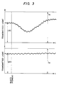
- Fig. 3 shows the changes with time of I1(t) and I2(t) as measured before and after the injection of a pigment.
- E b1 /E b2 is equal to E11/E2 (both values indicate the ratio of the absorptivity coefficient of hemoglobin in blood for light having a wavelength of ⁇ 1 to that of hemoglobin in blood for light having a wavelength of ⁇ 2)
- E b2 /Eg is known
- C b can be determined by actual measurement on collected blood
- ⁇ 1, I10 and I20 can be computed in the manner already described. Therefore, the time-dependent change in the concentration of a pigment of interest in blood can be determined over an adequately continuous period of time.
- Fig. 1 is a schematic block diagram of the apparatus.
- a light source is denoted by the numeral 1.
- Light issuing from this light source 1 is transmitted to light-receiving elements 4 and 5 through optical fibers 2 and 3, respectively.
- the filter 2 transmits light having a wavelength of ⁇ 1
- the filter 3 transmits light having a wavelength of ⁇ 2.
- Amplifier circuits 6 and 7 amplify the output signals from light-receiving elements 4 and 5, respectively.
- the optical fibers 2 and 3, light-receiving elements 4 and 5, and amplifier circuits 6 and 7 combine to make light quantity detecting means.
- the output signals from amplifier circuit 6 and 7 are supplied to logarithm computing circuits 8 and 9, respectively.
- Each of the circuits 8 and 9 convert the value of supplied signal to a logarithmic value and outputs a signal indicative of that logarithmic value.
- the output signal from the circuit 8 is supplied to each of a pulsating component extracting circuit 10, constant component extracting circuits 11 and 12, and a subtracter circuit 13.
- the output signal from the circuit 9 is supplied to each of a pulsating component extracting circuit 14, constant components extracting circuits 15 and 16, and a subtracter circuit 17.
- the circuits 10 and 14 extract the pulsating components of the output signals from logarithm computing circuits 8 and 9 and output the extracted pulsating components to a divider circuit 20.
- the divider circuit 20 divides the value of the output signal from the pulsating component extracting circuit 10 by the value of the output signal from the pulsating component extracting circuit 14, and supplies an appropriate signal to each of a ⁇ 1 memory circuit 21 and a ⁇ 2 memory circuit 22.
- the output signals from constant component extracting circuits 11 and 12 and from ⁇ 1 memory circuit 21 are supplied to an ischemic level computing circuit 23, and the output signals from constant component extracting circuits 15 and 16 and from ⁇ 2 memory circuit 22 are supplied to an ischemic level computing circuit 24. All of the circuits mentioned above are controlled in such a way that they are operated with a timing the values of which are predetermined by a control circuit (not shown).
- the constant component extracting circuits 11 and 12 extract, in response to a timing signal from said control circuit, the constant components of the output signal from the logarithm computing circuit 8 and store the extracted components.
- the constant component extracting circuits 15 and 16 extract, in response to a timing signal from said control circuit, the constant components of the output signal from the logarithm computing circuit 9 and store the extracted components.
- Each of the ⁇ 1 and ⁇ 2 memory circuits 21 and 22 stores and value of the output signal from the divider circuit 20 in response to a timing signal from said control circuit.
- the ischemic level computing circuit 23 (or 24) performs necessary calculations on the basis of the values stored in the constant component extracting circuits 11 and 12 (or 15 and 16) and in the in the ⁇ 1 memory circuit 21 (or ⁇ 2 memory circuit 22), determines the logarithm of the ischemic level for light having a wavelength of ⁇ 1 (or ⁇ 2), and stores the determined logarithmic value.
- the logarithm computing circuit 8 and 9, the pulsating component extracting circuits 10 and 14, the divider circuit 20, the constant component extracting circuits 11, 12, 15 and 16, and ⁇ 1 memory circuit 21, the ⁇ 2 memory circuit 22, and the ischemic level computing circuits 23 and 24 combine to make first computing means.
- the substracter 13 determines the difference between the value of output signal from the ischemic level computing circuits 23 (or 24) and the value of output signal from the logarithm computing circuits 8 (or 9) and outputs the difference to a divider circuits 25.
- the divider circuit 25 divides the value of output signal from the substracter circuits 13 by the value of output signal from the substracter 17, and outputs the results to a subtracter circuit 26.
- the subtracter circuit 26 determines the difference between the value of output signal from the divider circuit 25 and the value of output signal from the ⁇ 1 memory circuit 21 and outputs the result to a multiplier circuit 27.
- the multiplier circuit 27 multiplies the value of output signal from the substracter circuit 26 by a value associated with the value stored in a memory circuit 28, and outputs the product to a recording unit 29.
- the memory circuit 28 stores an externally set value of the hemoglobin concentration in blood.
- the logarithm computing circuits 8 and 9, the subtracter circuits 13 and 17, the divider circuit 25, the subtracter circuit 26, the multiplier circuit 27, and the memory circuit 28 combine to make second computing means.
- the operator prepares a sample of the living tissue to be analyzed and sets the sample 30 between light source 1 and each of the optical filters 2 and 3.
- the logarithm computing circuits 8 and 9 output signals that represent logI1(t) and logI2(t), respectively, which are the logarithms of I1(t) and I2(t) indicating the quantities of radiations of light having wavelengths of ⁇ 1 and ⁇ 2 that have been transmitted through the sample 30.
- the aforementioned control circuit (not shown) outputs a predetermined timing signal to each of the constant component extracting circuits 11 and 15 and the ⁇ 1 memory circuit 21.
- the circuit 11 extracts the constant components per heart beat of the signal value supplied from the logarithm computing circuit 8 (or 9) over a given duration of time, calculates the average of the extracted constant components, and stores the calculated average.
- the value stored in the constant component circuit 11 is logI11, shown in Fig. 2, which is the logarithm of I11, or the quantity or transmitted light having the wavelength ⁇ 1
- the value stored in the constraint component circuit 15 is log I21, also shown in Fig. 2, which is the logarithm of I21, or the quantity of transmitted light having the wavelength ⁇ 2.
- the ⁇ 1 memory circuit 21 also determines the average of signal values supplied per heart beat from the divider circuit 20 over the same duration of time, and stores this average.
- the value stored in the ⁇ 1 memory circuit 21 is ⁇ 1 which is expressed by equation (13).
- the operator causes a change in the absorptivity coefficient of blood in sample 30 with respect to light having the wavelength ⁇ 1. This may be done by changing the oxygen saturation of blood or by injecting a pigment into a blood vein.
- the control circuit (not shown) supplies a predetermined timing signal to each of the constant component extracting circuits 12 and 16 and the ⁇ 2 memory circuit 22.
- the constant component extracting circuit 12 (or 16) extracts the constant component per heart beat of the signal value supplied from the logarithm computing circuit 8 (or 9) over a given duration of time, calculates the average of these constant components, and stores the calculated average.
- the control circuit (not shown) then supplies a predetermined timing signal to each of the ischemic level computing circuits 23 and 24.
- the ischemic level computing circuit 23 (or 24) calculates logI10 or logI20) which is the logarithm of the ischemic level I10 (or I20) in accordance with equation (17) (or (18)).
- the operator injects into the sample 30 a pigment whose concentration is to be measured.
- the subtracter circuit 13 calculates the difference between logI10 (or logI20) stored in the ischemic level computing circuit 23 (or 24) and logI1(t) (or logI2(t)) supplied from the logarithm computing circuit 8 (or 9), and outputs the difference to the divider circuits 25. Accordingly, the divider circuits 25 outputs ⁇ (t) expressed by equation (21). Then, the subtracter circuit 26 calculates the difference between ⁇ (t) and the value of ⁇ 1 stored in ⁇ 1 memory circuit 21, and outputs the difference to the muliplier circuit 27.
- the multiplier circuits 27 holds a preliminarily loaded value of (E b2 /E g ) ⁇ C b , in which the component C b is supplied from the memory circuit 28 and, in the case under discussion, denotes the concentration of hemoglobin in the blood preliminarily collected from the sample of living tissue 30.
- the multiplier circuit 27 multiplies the value of ( ⁇ (t) - ⁇ 1) from the subtracter circuit 26 by (E b2 /E g ) ⁇ C b , and outputs the product to the recording unit 29. In this way, the multiplier circuit 27 determines C g (t) by performing calculations in accordance with equation (25) or (26). The values of C g (t) are recorded with unit 29 in a fully continuous manner.
- ⁇ 2, logI12 and logI22 to be used in calculating ischemic levels are determined by merely obtaining a single value of each parameter per heart beat and averaging the individual values, as in the case of determining fairly stable ⁇ 1, logI11 and logI21 (i.e., the values before pigment injection).
- this method is not capable of providing the correct values since ⁇ 2, logI12 and logI22, which are the values obtained either after pigment injection or after the change in the oxygen saturation of blood, have experienced marked changes.
- ⁇ 2, logI12 and logI22 are calculated by first obtaining a plurality of values for each parameter from the data for one heart beat, then averaging these values.
- the so determined values for each heart beat are stored as they are.
- the values of ⁇ 2, logI12 and logI22 for each heart beat are combined with those of ⁇ 1, logI11 and logI21 for each heart beat (the value of each parameter in the second group is stable and may be determined by averaging the values for a plurality of heart beats as described above) so as to compute logI10 and logI20 for each heart beat.
- logI10 and logI20 After computing these values of logI10 and logI20, those within the range where the pigment concentration is sufficiently high to be fairly stable are selected and averaged.
- the so obtained values of logI10 and logI20 are highly reliable and permit correct measurement of the change in pigment concentration.
- the operator is required to perform a prescribed sequence of operations each for the case of determining ischemic levels and for the case of constructing a pigment dilution curve C g (t) on the basis of the so determined ischemic levels.
- the operator may inject a pigment at a certain point of time, record all the values of logI1(t) and logI2(t) in a continuous manner over a duration of time including that point of time, determine ischemic levels by subsequently analyzing the recorded data, and construct a pigment dilution curve on the basis of the so determined ischemic levels.
- This method has the advantage that the operator needs to inject a pigment only once into the sample of living tissue to be analyzed.
- the apparatus shown in Fig. 1 is composed of analog circuitry. However, more rapid and precise measurements can be attained by performing A/D conversion on the signals produced from the light quantity detecting means, then performing subsequent processing with an electronic computer.
- the apparatus of the present invention is capable of measuring the change in the concentration of a pigment in blood in a fairly noninvasive and fully continuous manner.
Description
- The present invention relates to an apparatus for continuously measuring the change in the concentration of a pigment in blood in a living tissue.
- A technique known as pulse oximetry is capable of measuring the concentration of a pigment in the arterial blood in a living tissue in a noninvasive and continuous manner. However, the number of measurements that can be attained by this technique per heart beat is usually one, and no more than a few at maximum. This is because in order to attain one value of measurement by pulse oximetry, it is necessary to detect the quantity of light that has been transmitted through a pulsating blood at least at two points of time, which must be kept a part by a certain amount in order to ensure a correct value of measurement.
- The technique of pulse oximetry has the disadvantage that when the oxygen saturation of blood changes very rapidly or in such a case where the output of heart beat is to be calculated from a pigment dilution curve constructed by injecting a pigment into a blood vessel, it is impossible to measure the change in the concentration of the pigment in a fully continuous manner regardless of the cycle of heart beats.
- The present invention has been accomplished in order to eliminate this defect of the prior art technique. An object, therefore, of the present invention is to provide an apparatus capable of measuring the concentration of a pigment in blood in a noninvasive and fully continuous manner.
- The apparatus of the present invention comprises: light quantity detecting means for continuously detecting the quantities of radiations of light having different wavelengths that have been transmitted or reflected by a living tissue containing pulsating blood; first computing means which, when the concentration or absorptivity coefficient of a light-absorbing component in said blood changes with respect to light having either one of said wavelengths, computes the quantities of radiations of transmitted or reflected light having said wavelengths when said living tissue is in a state of ischemia on the basis of the constant and pulsating components of the quantity of each radiation of light that has been detected by said light quantity detecting means both before and after said change occurred; and second computing means which continuously determines the concentration of a pigment of interest in said blood by performing calculations based on the results of computation by said first computing means and on the quantities of radiations of light detected by said light quantity detecting means.
- The change in the concentration of a light-absorbing component may also be expressed as the change in the absorptivity of blood, so in the following description of the present invention discussion is made by referring to the change in absorptivity coefficient. The light quantity detecting means used in the apparatus of the present invention detects the quantity of light transmitted or reflected by a living tissue. The term "radiation of light reflected by a living tissue" means the light incident upon a living tissue that is refracted internally to go outside of the tissue. The following description is directed solely to transmitted light but it should be noted that the same explanation holds good for reflected light.
-
- Fig. 1 is a schematic block diagram of an apparatus according to one embodiment of the present invention; and
- Figs. 2 and 3 are diagrams illustrating the operating principle of the apparatus shown in Fig. 1.
- The apparatus of the present invention is operated in the following manner. The operator first causes a change in the absorptivity coefficient of blood with respect to a radiation of light having one wavelength. The first computing means determines the constant and pulsating components of the quantity of each of the radiations of transmitted light having different wavelengths on the basis of their quantities detected by said light quantity detecting means both before and after said change occurred, and computes from the determined values the ischemic level, or the quantity of each radiation of transmitted light when a living tissue being analyzed is in a state of ischemia. The second computing means continuously computes the concentration of a pigment of interest in blood on the basis of the ischemic levels computed by the first computing means and the quantities of radiations of light detected by the light quantity detecting means.
- The operating principle of an apparatus according to one embodiment of the present invention is hereunder described.
- Radiations of light having two different wavelengths, λ₁ and λ₂, are transmitted through a living tissue and the absorptivity coefficient of blood with respect to one wavelength, λ₁, is changed at a certain point of time by, for example, injecting a pigment into a blood vessel. Fig. 2 shows the resulting changes in the quantities of two radiations of transmitted light, I₁ and I₂. As shown, the values of I₁ and I₂ are subject to change in response to blood pulsations. In Fig. 2, the constant and pulsating components of transmitted light having a wavelength of λ₁ (or λ₂) before the absorptivity coefficient was changed are expressed by I₁₁ (or I₂₁) and ΔI₁₁ (orΔI₂₁), respectively, and the constant and pulsating components of transmitted having a wavelength of λ₁ (or λ₂) after the absorptivity coefficient was changed are expressed by I₁₂ (or I₂₂) and ΔI₁₂ (or ΔI₂₂), respectively. Suppose here that the absorptivity coefficient of blood with respect to light having the wavelength λ₁ is E₁₁ before it was changed, and E₂₁ after it was changed. On the other hand, the absorptivity coefficient of blood with respect to light having the wavelength λ₂ assumes a constant value of E₂.
- If the quantities of radiations of light having wavelengths λ₁ and λ₂ that have been transmitted through a living tissue in a state of ischemia are written as I₁₀ and I₂₀, respectively, then the following equations will hold good according to the general formula for determining the absorbance of light transmitted through a living tissue:


where C signifies the concentration of pigment contained in blood; D₁ and ΔD₁ denote the constant and pulsating components, respectively, of the thickness of a blood layer before the absorptivity coefficient was changed; and D₂ and ΔD₂ denote the constant and pulsating components, respectively, of the thickness of a blood layer after the absorptivity coefficient was changed. - Since


Equations (2) to (4) can be rewritten in like manner. When the pulsating and constant components are separately extracted from each of the rewritten equations, the following relations are established: -


-


Divide equation (5) by equation (7) and write the quotient as φ₂. In like manner, divide equation (6) by equation (8) and write the quotient as φ₂. The results are as follows:


- By measuring the values of ΔlogI₁₁, ΔlogI₂₁, ΔlogI₁₂ and ΔlogI₂₂, φ₁ and φ₂ can be determined from equations (13) and (14).
- From equations (9) and (11), the following relation is obtained:

Since

In like manner, the following equation is derived from equations (10) and (12):

- From equation (15) and (16),


- By determining the values of φ₁, φ₂, I₁₁, I₁₂, I₂₁ and I₂₂, two ischemic levels I₁₀ and I₂₀ can be calculated from equations (17) and (18), respectively.
- Using the so determined ischemic levels I₁₀ and I₂₀, a pigment dilution curve is constructed in the following manner.
- First suppose that a pigment to be injected into a blood vessel has an absorptivity coefficient of Eg with respect to light having a wavelength of λ₁, and a value of zero (no light absorption) with respect to light having a wavelength of λ₂. Also suppose that this pigment is present in blood at a concentration of Cg. The hemoglobin in blood is supposed to have an absorptivity coefficient of Eb1 with respect to light having a wavelength of λ₁, and Eb2 with respect to light having a wavelength of λ₂.
- The quantity of light having the wavelength λ₁ that has been transmitted through a living tissue is a function of time and can be written as I₁(t). In like manner, the quantity of light having the wavelength λ₂ that has been transmitted through the living tissue is written as I₂(t). D is a function of time and hence, be expressed as D(t). Fig. 3 shows the changes with time of I₁(t) and I₂(t) as measured before and after the injection of a pigment. Using the ischemic levels, I₁₀ and I₂₀, the absorbance of light that has been transmitted through a blood layer having a thickness of D can be expressed as follows:


Divide equation (19) by equation (20) and write the quotient as follows:

Then, the following relation is obtained:

Equation (22) can be rewritten as:

- Since Eb1/Eb2 is equal to E₁₁/E₂ (both values indicate the ratio of the absorptivity coefficient of hemoglobin in blood for light having a wavelength of λ₁ to that of hemoglobin in blood for light having a wavelength of λ₂),

Therefore, equation (23) can be rewritten either as:

or as:

In these equations, Eb2/Eg is known, Cb can be determined by actual measurement on collected blood, and φ₁, I₁₀ and I₂₀ can be computed in the manner already described. Therefore, the time-dependent change in the concentration of a pigment of interest in blood can be determined over an adequately continuous period of time. - An example of the apparatus that is designed to operate by the principle outlined above is described hereinafter.
- Fig. 1 is a schematic block diagram of the apparatus. In the figure, a light source is denoted by the numeral 1. Light issuing from this light source 1 is transmitted to light-receiving
elements optical fibers filter 2 transmits light having a wavelength of λ₁, and thefilter 3 transmits light having a wavelength of λ₂.Amplifier circuits elements optical fibers elements amplifier circuits - The output signals from
amplifier circuit logarithm computing circuits circuits circuit 8 is supplied to each of a pulsatingcomponent extracting circuit 10, constantcomponent extracting circuits subtracter circuit 13. The output signal from thecircuit 9 is supplied to each of a pulsatingcomponent extracting circuit 14, constantcomponents extracting circuits subtracter circuit 17. Thecircuits logarithm computing circuits divider circuit 20. Thedivider circuit 20 divides the value of the output signal from the pulsatingcomponent extracting circuit 10 by the value of the output signal from the pulsatingcomponent extracting circuit 14, and supplies an appropriate signal to each of aφ₁ memory circuit 21 and aφ₂ memory circuit 22. The output signals from constantcomponent extracting circuits φ₁ memory circuit 21 are supplied to an ischemiclevel computing circuit 23, and the output signals from constantcomponent extracting circuits φ₂ memory circuit 22 are supplied to an ischemiclevel computing circuit 24. All of the circuits mentioned above are controlled in such a way that they are operated with a timing the values of which are predetermined by a control circuit (not shown). The constantcomponent extracting circuits logarithm computing circuit 8 and store the extracted components. The constantcomponent extracting circuits logarithm computing circuit 9 and store the extracted components. Each of the φ₁ andφ₂ memory circuits divider circuit 20 in response to a timing signal from said control circuit. The ischemic level computing circuit 23 (or 24) performs necessary calculations on the basis of the values stored in the constantcomponent extracting circuits 11 and 12 (or 15 and 16) and in the in the φ₁ memory circuit 21 (or φ₂ memory circuit 22), determines the logarithm of the ischemic level for light having a wavelength of λ₁ (or λ₂), and stores the determined logarithmic value. Thelogarithm computing circuit component extracting circuits divider circuit 20, the constantcomponent extracting circuits φ₁ memory circuit 21, theφ₂ memory circuit 22, and the ischemiclevel computing circuits - Shown by 13 and 17 in Fig. 1 are substracter circuits. The substracter 13 (or 17) determines the difference between the value of output signal from the ischemic level computing circuits 23 (or 24) and the value of output signal from the logarithm computing circuits 8 (or 9) and outputs the difference to a
divider circuits 25. Thedivider circuit 25 divides the value of output signal from thesubstracter circuits 13 by the value of output signal from thesubstracter 17, and outputs the results to asubtracter circuit 26. Thesubtracter circuit 26 determines the difference between the value of output signal from thedivider circuit 25 and the value of output signal from theφ₁ memory circuit 21 and outputs the result to amultiplier circuit 27. Themultiplier circuit 27 multiplies the value of output signal from thesubstracter circuit 26 by a value associated with the value stored in amemory circuit 28, and outputs the product to arecording unit 29. Thememory circuit 28 stores an externally set value of the hemoglobin concentration in blood. Thelogarithm computing circuits subtracter circuits divider circuit 25, thesubtracter circuit 26, themultiplier circuit 27, and thememory circuit 28 combine to make second computing means. - The apparatus having the construction described above will be operated in the following manner.
- In the first step, the operator prepares a sample of the living tissue to be analyzed and sets the
sample 30 between light source 1 and each of theoptical filters logarithm computing circuits sample 30. The aforementioned control circuit (not shown) outputs a predetermined timing signal to each of the constantcomponent extracting circuits φ₁ memory circuit 21. In response to this timing signal, the circuit 11 (or 15) extracts the constant components per heart beat of the signal value supplied from the logarithm computing circuit 8 (or 9) over a given duration of time, calculates the average of the extracted constant components, and stores the calculated average. The value stored in theconstant component circuit 11 is logI₁₁, shown in Fig. 2, which is the logarithm of I₁₁, or the quantity or transmitted light having the wavelength λ₁, and the value stored in theconstraint component circuit 15 is log I₂₁, also shown in Fig. 2, which is the logarithm of I₂₁, or the quantity of transmitted light having the wavelength λ₂. Theφ₁ memory circuit 21 also determines the average of signal values supplied per heart beat from thedivider circuit 20 over the same duration of time, and stores this average. The value stored in theφ₁ memory circuit 21 is φ₁ which is expressed by equation (13). - In the next step, the operator causes a change in the absorptivity coefficient of blood in
sample 30 with respect to light having the wavelength λ₁. This may be done by changing the oxygen saturation of blood or by injecting a pigment into a blood vein. After a change has occurred in the absorptivity coefficient of blood, the control circuit (not shown) supplies a predetermined timing signal to each of the constantcomponent extracting circuits φ₂ memory circuit 22. In response to this timing signal, the constant component extracting circuit 12 (or 16) extracts the constant component per heart beat of the signal value supplied from the logarithm computing circuit 8 (or 9) over a given duration of time, calculates the average of these constant components, and stores the calculated average. The value stored in the constantcomponent extracting circuit 12 is logI₁₂, shown in Fig. 2, which is the logarithm of I₁₂, or the quantity of transmitted light having the wavelength λ₁, and the value stored in the constantcomponent extracting circuit 16 is logI₂₂, also shown in Fig. 2, which is the loagrithm of I₂₂, or the quantity of transmitted light having the wavelength λ₂. Theφ₂ memory circuit 22 also determines the average of signal values supplied per heart beat from thedivider circuit 20 over a second period of time having the same predetermined length of duration, and stores this average. The value stored in theφ₂ memory circuit 22 is φ₂ expressed by equation (14). - The control circuit (not shown) then supplies a predetermined timing signal to each of the ischemic
level computing circuits - In a subsequent step, the operator injects into the sample 30 a pigment whose concentration is to be measured. The subtracter circuit 13 (or 17) calculates the difference between logI₁₀ (or logI₂₀) stored in the ischemic level computing circuit 23 (or 24) and logI₁(t) (or logI₂(t)) supplied from the logarithm computing circuit 8 (or 9), and outputs the difference to the
divider circuits 25. Accordingly, thedivider circuits 25 outputs Ψ(t) expressed by equation (21). Then, thesubtracter circuit 26 calculates the difference between Ψ(t) and the value of φ₁ stored inφ₁ memory circuit 21, and outputs the difference to themuliplier circuit 27. Themultiplier circuits 27 holds a preliminarily loaded value of (Eb2/Eg)·Cb, in which the component Cb is supplied from thememory circuit 28 and, in the case under discussion, denotes the concentration of hemoglobin in the blood preliminarily collected from the sample of livingtissue 30. Themultiplier circuit 27 multiplies the value of (Ψ(t) - φ₁) from thesubtracter circuit 26 by (Eb2/Eg)·Cb, and outputs the product to therecording unit 29. In this way, themultiplier circuit 27 determines Cg(t) by performing calculations in accordance with equation (25) or (26). The values of Cg(t) are recorded withunit 29 in a fully continuous manner. - In the embodiment under discussion, φ₂, logI₁₂ and logI₂₂ to be used in calculating ischemic levels are determined by merely obtaining a single value of each parameter per heart beat and averaging the individual values, as in the case of determining fairly stable φ₁, logI₁₁ and logI₂₁ (i.e., the values before pigment injection). However, this method is not capable of providing the correct values since φ₂, logI₁₂ and logI₂₂, which are the values obtained either after pigment injection or after the change in the oxygen saturation of blood, have experienced marked changes. In order to overcome this defect, φ₂, logI₁₂ and logI₂₂ are calculated by first obtaining a plurality of values for each parameter from the data for one heart beat, then averaging these values. In the next place, the so determined values for each heart beat are stored as they are. In determining ischemic levels, the values of φ₂, logI₁₂ and logI₂₂ for each heart beat are combined with those of φ₁, logI₁₁ and logI₂₁ for each heart beat (the value of each parameter in the second group is stable and may be determined by averaging the values for a plurality of heart beats as described above) so as to compute logI₁₀ and logI₂₀ for each heart beat. After computing these values of logI₁₀ and logI₂₀, those within the range where the pigment concentration is sufficiently high to be fairly stable are selected and averaged. The so obtained values of logI₁₀ and logI₂₀ are highly reliable and permit correct measurement of the change in pigment concentration.
- In working with the apparatus shown in Fig. 1, the operator is required to perform a prescribed sequence of operations each for the case of determining ischemic levels and for the case of constructing a pigment dilution curve Cg(t) on the basis of the so determined ischemic levels. If desired, the operator may inject a pigment at a certain point of time, record all the values of logI₁(t) and logI₂(t) in a continuous manner over a duration of time including that point of time, determine ischemic levels by subsequently analyzing the recorded data, and construct a pigment dilution curve on the basis of the so determined ischemic levels. This method has the advantage that the operator needs to inject a pigment only once into the sample of living tissue to be analyzed.
- The apparatus shown in Fig. 1 is composed of analog circuitry. However, more rapid and precise measurements can be attained by performing A/D conversion on the signals produced from the light quantity detecting means, then performing subsequent processing with an electronic computer.
- Although a single light source and two light receiving elements are used in the foregoing embodiment, it is apparent that the invention is not limited thereto and thereby. For example, it is possible to use a single light receiving element for two alternatively lighting light sources in a time-divisional manner.
- As described on the foregoing pages, the apparatus of the present invention is capable of measuring the change in the concentration of a pigment in blood in a fairly noninvasive and fully continuous manner.
Claims (4)
- An apparatus for measuring the change in the concentration of a pigment in blood which comprises: light quantity detecting means (2-7) for continuously detecting the quantities of radiations of light (I₁,(t), I₂(t)) having different wavelengths (λ₁, λ₂) that have been transmitted or reflected by a living tissue (30) containing pulsating blood; first computing means (8-12, 14-16, 20-24) which, when the concentration or absorptivity coefficient of a light-absorbing component in said blood is changed with respect to light having either one of said wavelengths (λ₁, λ₂), computes the quantities of radiations (I₁₀, I₂₀) of transmitted or reflected light having said wavelengths (λ₁, λ₂) when said living tissue is in a state of ischemia on the basis of the constant and pulsating components of the quantity of each radiation of light that has been detected by said light quantity detecting means both before and after said change occurred; and second computing means (13, 17, 25-29) which continuously determines the concentration (Cg(t)) of a pigment of interest in said blood by performing calculations based on the results (I₁₀, I₂₀) of computation by said first computing means and on the quantities of radiations of light (I₁(t), I₂(t)) detected by said light quantity detecting means.
- An apparatus according to claim 1 wherein said first computing means is a processor that performs digital processing on the output of said light quantity detecting means.
- An apparatus according to claim 1 wherein said second computing means is a processor that performs digital processing on the outputs of said light quantity detecting means and said first computing means.
- An apparatus according to claim 2 wherein said second computing means is a processor that performs digital processing on the outputs of said light quantity detecting means and said first computing means.
Applications Claiming Priority (2)
| Application Number | Priority Date | Filing Date | Title |
|---|---|---|---|
| JP61314784A JPS63165757A (en) | 1986-12-26 | 1986-12-26 | Apparatus for measuring change in concentration of pigment in blood |
| JP314784/86 | 1986-12-26 |
Publications (2)
| Publication Number | Publication Date |
|---|---|
| EP0276477A1 EP0276477A1 (en) | 1988-08-03 |
| EP0276477B1 true EP0276477B1 (en) | 1992-10-28 |
Family
ID=18057551
Family Applications (1)
| Application Number | Title | Priority Date | Filing Date |
|---|---|---|---|
| EP19870119210 Expired EP0276477B1 (en) | 1986-12-26 | 1987-12-24 | Apparatus for measuring the change in the concentration of a pigment in blood |
Country Status (3)
| Country | Link |
|---|---|
| EP (1) | EP0276477B1 (en) |
| JP (1) | JPS63165757A (en) |
| DE (1) | DE3782416T2 (en) |
Families Citing this family (8)
| Publication number | Priority date | Publication date | Assignee | Title |
|---|---|---|---|---|
| JPH01129838A (en) * | 1987-11-13 | 1989-05-23 | Sumitomo Electric Ind Ltd | Liver function examination apparatus |
| CA1328018C (en) * | 1987-11-13 | 1994-03-22 | Masahiko Kanda | Liver function testing apparatus |
| JPH0657216B2 (en) * | 1988-09-14 | 1994-08-03 | 住友電気工業株式会社 | Liver function test device |
| JPH02111343A (en) * | 1988-10-21 | 1990-04-24 | Koorin Denshi Kk | Reflecting oxymeter |
| SE8902014L (en) * | 1989-06-02 | 1990-12-03 | Gambro Ab | AUTOTRANSFUSION SYSTEM FOR COLLECTION, TREATMENT AND TRANSFER OF A PATIENT'S BLOOD |
| IE912141A1 (en) * | 1990-07-06 | 1992-01-15 | Kapsch Ag | Method and device for qualitative and quantitative¹determination of tissue-specific parameters of a biological¹tissue |
| JP3364819B2 (en) * | 1994-04-28 | 2003-01-08 | 日本光電工業株式会社 | Blood absorption substance concentration measurement device |
| CN108872100B (en) * | 2018-04-13 | 2021-01-08 | 浙江省计量科学研究院 | Multi-time enhanced spectrum high-precision ammonia gas detection device and detection method |
Family Cites Families (3)
| Publication number | Priority date | Publication date | Assignee | Title |
|---|---|---|---|---|
| JPS5725217B2 (en) * | 1974-10-14 | 1982-05-28 | ||
| US4167331A (en) * | 1976-12-20 | 1979-09-11 | Hewlett-Packard Company | Multi-wavelength incremental absorbence oximeter |
| ZA861179B (en) * | 1985-02-28 | 1986-12-30 | Boc Group Inc | Oximeter |
-
1986
- 1986-12-26 JP JP61314784A patent/JPS63165757A/en active Granted
-
1987
- 1987-12-24 DE DE19873782416 patent/DE3782416T2/en not_active Expired - Fee Related
- 1987-12-24 EP EP19870119210 patent/EP0276477B1/en not_active Expired
Also Published As
| Publication number | Publication date |
|---|---|
| JPH0562541B2 (en) | 1993-09-08 |
| JPS63165757A (en) | 1988-07-09 |
| EP0276477A1 (en) | 1988-08-03 |
| DE3782416T2 (en) | 1993-03-11 |
| DE3782416D1 (en) | 1992-12-03 |
Similar Documents
| Publication | Publication Date | Title |
|---|---|---|
| US5190040A (en) | Apparatus for measuring the change in the concentration of a pigment in blood | |
| US4832484A (en) | Apparatus for determining the concentration of a light-absorbing material in blood | |
| US4854699A (en) | Backscatter oximeter | |
| US5999841A (en) | Apparatus for measuring circulating blood volume | |
| EP0679890A1 (en) | Apparatus for determining the concentration of light-absorbing materials in blood | |
| US5685301A (en) | Apparatus for precise determination of operating characteristics of optical devices contained in a monitoring probe | |
| US4266554A (en) | Digital oximeter | |
| EP0224571B1 (en) | Method and apparatus for determining oxygen saturation in vivo | |
| CA1037285A (en) | Ear oximetry process and apparatus | |
| US8507281B2 (en) | Method of removing abnormal data and blood component spectroscopy analysis system employing the same | |
| US5154176A (en) | Liver function testing apparatus | |
| JPS63252239A (en) | Reflection type oxymeter | |
| US5048524A (en) | Blood parameter measurement | |
| JP3270917B2 (en) | Oxygen saturation measuring device, blood light absorbing substance concentration measuring device, and biological signal processing method | |
| EP2087836B1 (en) | Apparatus and method for determining a physiological parameter | |
| EP0276477B1 (en) | Apparatus for measuring the change in the concentration of a pigment in blood | |
| US4676252A (en) | Double indicator pulmonary edema measurement | |
| US4403615A (en) | Thermal method for measuring blood perfusion | |
| US5774223A (en) | Optical measuring method and an optical measuring apparatus for determining the internal structure of an object | |
| JPH02309929A (en) | Hepatic function inspecting apparatus | |
| RU2093064C1 (en) | Liver function analysis device | |
| US4905703A (en) | Liver function testing apparatus and method | |
| EP2281504A1 (en) | Apparatus and method for determining a physiological parameter | |
| Guier et al. | Beat-by-beat stroke volume from aortic-pulse-pressure analysis | |
| JPS63218841A (en) | Apparatus for measuring concentration of light absorbing substance in blood |
Legal Events
| Date | Code | Title | Description |
|---|---|---|---|
| PUAI | Public reference made under article 153(3) epc to a published international application that has entered the european phase |
Free format text: ORIGINAL CODE: 0009012 |
|
| AK | Designated contracting states |
Kind code of ref document: A1 Designated state(s): DE FR GB IT NL SE |
|
| 17P | Request for examination filed |
Effective date: 19890203 |
|
| 17Q | First examination report despatched |
Effective date: 19911212 |
|
| GRAA | (expected) grant |
Free format text: ORIGINAL CODE: 0009210 |
|
| AK | Designated contracting states |
Kind code of ref document: B1 Designated state(s): DE FR GB IT NL SE |
|
| REF | Corresponds to: |
Ref document number: 3782416 Country of ref document: DE Date of ref document: 19921203 |
|
| ITF | It: translation for a ep patent filed |
Owner name: SOCIETA' ITALIANA BREVETTI S.P.A. |
|
| ET | Fr: translation filed | ||
| PLBE | No opposition filed within time limit |
Free format text: ORIGINAL CODE: 0009261 |
|
| STAA | Information on the status of an ep patent application or granted ep patent |
Free format text: STATUS: NO OPPOSITION FILED WITHIN TIME LIMIT |
|
| 26N | No opposition filed | ||
| ITTA | It: last paid annual fee | ||
| EAL | Se: european patent in force in sweden |
Ref document number: 87119210.0 |
|
| PGFP | Annual fee paid to national office [announced via postgrant information from national office to epo] |
Ref country code: SE Payment date: 19981125 Year of fee payment: 12 |
|
| PGFP | Annual fee paid to national office [announced via postgrant information from national office to epo] |
Ref country code: GB Payment date: 19981224 Year of fee payment: 12 |
|
| PGFP | Annual fee paid to national office [announced via postgrant information from national office to epo] |
Ref country code: NL Payment date: 19981231 Year of fee payment: 12 Ref country code: FR Payment date: 19981231 Year of fee payment: 12 |
|
| PGFP | Annual fee paid to national office [announced via postgrant information from national office to epo] |
Ref country code: DE Payment date: 19990127 Year of fee payment: 12 |
|
| PG25 | Lapsed in a contracting state [announced via postgrant information from national office to epo] |
Ref country code: GB Free format text: LAPSE BECAUSE OF NON-PAYMENT OF DUE FEES Effective date: 19991224 |
|
| PG25 | Lapsed in a contracting state [announced via postgrant information from national office to epo] |
Ref country code: SE Free format text: LAPSE BECAUSE OF NON-PAYMENT OF DUE FEES Effective date: 19991225 |
|
| PG25 | Lapsed in a contracting state [announced via postgrant information from national office to epo] |
Ref country code: NL Free format text: LAPSE BECAUSE OF NON-PAYMENT OF DUE FEES Effective date: 20000701 |
|
| EUG | Se: european patent has lapsed |
Ref document number: 87119210.0 |
|
| GBPC | Gb: european patent ceased through non-payment of renewal fee |
Effective date: 19991224 |
|
| PG25 | Lapsed in a contracting state [announced via postgrant information from national office to epo] |
Ref country code: FR Free format text: LAPSE BECAUSE OF NON-PAYMENT OF DUE FEES Effective date: 20000831 |
|
| NLV4 | Nl: lapsed or anulled due to non-payment of the annual fee |
Effective date: 20000701 |
|
| PG25 | Lapsed in a contracting state [announced via postgrant information from national office to epo] |
Ref country code: DE Free format text: LAPSE BECAUSE OF NON-PAYMENT OF DUE FEES Effective date: 20001003 |
|
| REG | Reference to a national code |
Ref country code: FR Ref legal event code: ST |
|
| PG25 | Lapsed in a contracting state [announced via postgrant information from national office to epo] |
Ref country code: IT Free format text: LAPSE BECAUSE OF NON-PAYMENT OF DUE FEES;WARNING: LAPSES OF ITALIAN PATENTS WITH EFFECTIVE DATE BEFORE 2007 MAY HAVE OCCURRED AT ANY TIME BEFORE 2007. THE CORRECT EFFECTIVE DATE MAY BE DIFFERENT FROM THE ONE RECORDED. Effective date: 20051224 |