EP0276417B1 - Printing apparatus having coating function - Google Patents
Printing apparatus having coating function Download PDFInfo
- Publication number
- EP0276417B1 EP0276417B1 EP87118002A EP87118002A EP0276417B1 EP 0276417 B1 EP0276417 B1 EP 0276417B1 EP 87118002 A EP87118002 A EP 87118002A EP 87118002 A EP87118002 A EP 87118002A EP 0276417 B1 EP0276417 B1 EP 0276417B1
- Authority
- EP
- European Patent Office
- Prior art keywords
- rotary shaft
- cylinder
- printing apparatus
- coating
- ink
- Prior art date
- Legal status (The legal status is an assumption and is not a legal conclusion. Google has not performed a legal analysis and makes no representation as to the accuracy of the status listed.)
- Expired - Lifetime
Links
Images



Classifications
-
- B—PERFORMING OPERATIONS; TRANSPORTING
- B41—PRINTING; LINING MACHINES; TYPEWRITERS; STAMPS
- B41F—PRINTING MACHINES OR PRESSES
- B41F23/00—Devices for treating the surfaces of sheets, webs, or other articles in connection with printing
- B41F23/08—Print finishing devices, e.g. for glossing prints
-
- Y—GENERAL TAGGING OF NEW TECHNOLOGICAL DEVELOPMENTS; GENERAL TAGGING OF CROSS-SECTIONAL TECHNOLOGIES SPANNING OVER SEVERAL SECTIONS OF THE IPC; TECHNICAL SUBJECTS COVERED BY FORMER USPC CROSS-REFERENCE ART COLLECTIONS [XRACs] AND DIGESTS
- Y10—TECHNICAL SUBJECTS COVERED BY FORMER USPC
- Y10S—TECHNICAL SUBJECTS COVERED BY FORMER USPC CROSS-REFERENCE ART COLLECTIONS [XRACs] AND DIGESTS
- Y10S101/00—Printing
- Y10S101/49—Convertible printing press, e.g. lithographic to letter press
Definitions
- This invention relates to a printing apparatus which enables coating operation as needed in addition to numbering and imprinting.
- Printed matters which require a good-looking appearance such as book covers, catalogs, and pamphlets are often coated with a varnish which forms a film on the printed paper to prevent the surface from staining and give it a gloss.
- the coating operation may be performed by an independent device (coater), but in many cases carried out by a coater provided in a delivery passage of a printing apparatus to perform the coating operation immediately following the print operation for improved working efficiency.
- a numbering and imprinting device is provided in the delivery passage of the printing apparatus for partial imprinting or numbering.
- a numbering device can be attached to a printing shaft to perform numbering, or a relief imprinting cylinder in place of the numbering device can be attached to the printing shaft to perform imprinting.
- the coater or the numbering and imprinting device is provided as an independent device.
- the printing shaft of the numbering and imprinting device is normally divided into shaft supporting sections at both ends of the shaft and a central section to support the numbering device or the like, in order to facilitate attaching and detaching of the numbering device or an relief imprinting cylinder to and from the printing shaft and cleaning of an impression cylinder which is located at the rear side of the printing shaft.
- the central section of the printing shaft can be solely removed from the printing apparatus, and the numbering device or the relief imprinting cylinder can be attached to the removed central section of the printing shaft, thereby facilitating attaching the device.
- the removal of the central section of the printing shaft makes a space in the printing apparatus, which facilitates cleaning the inside of the printing apparatus.
- the central section of the shaft is detachably mounted on the shaft supporting sections with retaining means such as bolts, the central section is possibly mounted eccentrically relative to the shaft supporting sections with restricted mounting accuracy.
- a coating cylinder to coat a varnish or the like on the print paper in combination with the impression cylinder is required to make exact rotation. If the coating cylinder rotates eccentrically, the distance between the coating cylinder surface and the impression cylinder varies in a turn with a variation in contact pressure, which results in uneven thickness of the coating layer.
- US-A 3,999,480 discloses a printing apparatus with an integral rotary shaft but without a coating cylinder mounted thereon.
- FR-A 2.183.153 discloses a printing apparatus wherein one and the same impression cylinder cooperates with the coating unit and with a blanket cylinder.
- EP-A 0 115 855 discloses a printing apparatus provided with a secondary printing couple comprising a coating unit.
- the invention relates to a printing apparatus with an integral rotary shaft (13) disposed adjacent to an impression cylinder (5), which rotary shaft (13) is supported at its both ends on main unit frames (25) and driven to rotate synchronized with said impression cylinder (5) as well as a numbering device (67) and a relief imprinting cylinder (71) alternatively mounted detachably on said rotary shaft (13) which apparatus further has an ink unit (17) detachably mounted on a printing apparatus main unit (15) for supplying ink to said numbering device (67) or said relief imprinting cylinder (71), characterized in that said numbering device (67) and said relief imprinting cylinder (71) may be substituted by a coating cylinder (69) which can be detachably mounted on said rotary shaft (13) and that a coater unit (19) for supplying a coating material to said coating cylinder (69) may be detachably mounted on said printing apparatus main unit (15) in substitution of said ink unit (17); and wherein said rotary shaft (13) is supported at its
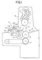
- Fig.1 is a schematic view of an embodiment of the sheet-feed offset printing apparatus according to the present invention.
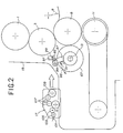
- Fig.2 is a schematic view showing part of the embodiment of the sheet-feed offset printing apparatus shown in Fig.1.
- Fig.3 is a schematic vertical sectional view of of a rotary shaft provided with a coating cylinder.
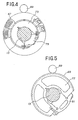
- Fig.4 and Fig.5 are side views of a numbering device and the coating cylinder, respectively.
- Fig.6 is a schematic oblique view showing a relief imprinting cylinder mounted on the rotary shaft.
- Fig.7 is a schematic view of the printing apparatus according to the present invention which is set up for coating operation.
- numeral 1 indicates a plate cylinder
- numeral 3 indicates a blanket cylinder
- number 5 indicates an impression cylinder
- numeral 7 indicates an ink feeder for plate cylinder
- number 9 indicates a sheet feeder
- numeral 11 indicates a sheet discharger.
- a line pattern transferred from the plate cylinder 1 to the blanket cylinder is imprinted on a sheet of paper supplied from the sheet feeder 9 into between the blanket cylinder 3 and the impression cylinder 5, and the printed sheet is discharged by the sheet discharger 11.
- a rotary shaft 13 is disposed adjacent to the impression cylinder 5, which is commonly used for numbering, imprinting, and coating.
- An ink unit 17 is detachably mounted opposing the rotary shaft 13 on a printing apparatus main unit 15.
- the mounting location of the ink unit 17 on the printing apparatus main unit 15 can be detachably mounted with a coater unit 19 which will be described later herein, alternatively to the ink unit 17 (Fig.7).
- the rotary shaft 13 is an integrally formed cylinder, supported at its both ends by eccentric bushings 23 through bearing metals 21, and the eccentric bushings 24 are supported by main unit frames 25.
- the eccentric bushings 23 are rotatably supported by the main unit frames 25 and have an eccentricity e between the center of the inner peripheral surfaces of the bushings 23 contacting with the bearing metals 21 and the center of the outer peripheral surfaces contacting with the main unit frames 25, thereby allowing movement of the axial center position of the rotary shaft 13 by changing the phase angle of the eccentric bushings 23 through rods 27 mounted on the eccentric bushings 23.
- the rotary shaft 13 is moved and the distance between axial centers of the rotary shaft 13 and the impression cylinder 5 is adjusted for adapting for the thickness of paper to be printed and withdrawal of the rotary shaft 13 in the event of a malfunction.
- the rotary shaft 13 can be removed and inserted in the axial direction with the bearing metals 21 attached to the main unit frames 25.
- the central part of the rotary shaft 13 other than its both ends supported by the bearings has a smaller diameter by more than its fitting tolerance than the inner diameter of the bearing metals 21. Therefore, by removing a plate position adjusting device which will be described later, the rotary shaft 13 can be easily removed with the bearing metals 21 left on the main unit frames 25, thereby improving the workability in cleaning the impression cylinder 5.
- the rotary shaft 13 has the plate position adjusting device for fine adjustment of the axial position of the rotary shaft 13 and its rotational phase relative to the impression cylinder 5.
- a disk 31 is mounted at one end of the rotary shaft 13 (left end in Fig.3) through a bracket 29, and an axial adjusting shaft 33 is connected unmovably in the axial direction but rotatably to the rotary shaft 13 through thrust bearings 32 disposed at both sides of the disk 31.
- the axial adjusting shaft 33 is screwed in a nut 37 of a supporting frame 35 fixed to the main unit frame 25, and is normally fixed to the supporting frame 35 with a lock nut 39.
- a knob 31 is provided at the end of the axial adjusting shaft 33.
- the knob 41 can be turned to rotate the axial adjusting shaft 33 and move it forward and reverse, which is screwed in with the nut 37, thereby transmitting the movement to the rotary shaft 13 through the disk 31 to move the rotary shaft 33 axially.
- the axial position of the rotary shaft 13 is adjusted.
- a spur gear 43 is mounted at the other end of the rotary shaft 13 (right end in Fig.3), which engages with an internal spur gear 48 provided in a drive gear member 45.
- the drive gear member 45 engaged with the spur gear 43 can be moved relatively in the axial direction together with the spur gear 43.
- a helical gear 49 is provided on the outer periphery of the drive gear member 45, and the helical gear 49 engages with an impression cylinder gear which is not shown.
- rotation of the impression cylinder 5 is transmitted to the drive gear member 45 through the helical gear 49 which, through the spur gear 43, further rotates the rotary shaft 13 in synchronization with the impression cylinder 5.
- the drive gear member 45 is mounted with a disk 51, and connected with a circumferential adjusting shaft 55 through a thrust bearing 53 similarly to the construction of the left end of the rotary shaft 13.
- the circumferential adjusting shaft 55 is screwed with a nut 59 of a supporting frame 57 mounted on the main unit frame 25 and normally fixed to the supporting frame 57 with a lock nut 61. With the lock nut 61 loosened, a knob 63 which is provided at the end of the circumferential adjusting shaft 55 can be turned to rotate the circumferential adjusting shaft 55 and move it forward and reverse in the axial direction, thereby moving the drive gear member 45 in the axial direction.
- the axial movement of the drive gear member 45 changes the engaging phase of the helical gear 49 with the impression cylinder gear, thereby adjusting the rotational phase of the rotary shaft 13 relative to the impression cylinder 5.
- the movement of the rotary shaft 13 by the axial adjusting shaft 33 and the relative axial movement of the spur gear 43 and the drive gear member 45 through the movement of the drive gear member 45 by the circumferential adjusting shaft 55 are absorbed by a relative movement of the spur gear 43 and the drive gear member 45 in the gear tooth direction.
- the printing position or coating position can be adjusted horizontally and vertically by the axial and circumferential movement of the rotary shaft 13.
- Numeral 65 in Fig.3 indicates a cover.
- the rotary shaft 13 is detachably mounted alternatively with a numbering device 67 as shown in Fig.4, a coating cylinder 69 as shown in Fig.5, or a relief imprinting cylinder 71 as shown in Fig.6.
- Fig.3 shows the rotary shaft 13 mounted with the coating cylinder 69.
- Each of the numbering device 67, the coating cylinder 69, and the relief imprinting cylinder 71 is cut out of part of its circumference so that it can be mounted and detached from the peripheral surface of the rotary shaft 13, and the cutout can be detachably mounted with a cap.
- the numbering device 67 is mounted on a mount 73 having a cutout which allows the rotary shaft 13 to pass, so that the position of the numbering device 67 can be circumferentially adjusted.
- the mount 73 can be mounted at any axial position on the rotary shaft 13 so that the rotary shaft 13 is placed between the mount 73 and a cap 75.
- the coating cylinder 69 comprises a mount 77 with a partial cutout and a resin sheet stuck on the outer peripheral surface of the mount 77, and is detachably mounted on the rotary shaft so that the rotary shaft 13 is pinched between the mount 77 and a cap 81 as for the case of the numbering device 67.
- the sheet on the surface of the coating cylinder 69 is provided on a part corresponding to that to be coated.
- the sheet is provided on the overall surface of the coating cylinder 69, or to coat partly, the sheet is provided only on the corresponding part of the surface of the coating cylinder 69.
- the relief imprinting cylinder 71 can be detachably mounted on the rotary shaft 13 using a mount 83 and a cap 85.
- one of the numbering device 67, the coating cylinder 69, and the relief imprinting cylinder 71 is alternatively mounted on the rotary shaft 13 as needed.
- the bosses of the levers 87 have projecting mounting pieces 91.
- Springs 93 are stretchedly provided between the mounting pieces 91 and the main unit frames 25, and the stretching force of the springs 93 urges the levers 87 counter-clockwise in Fig.2.
- the levers 87 are mounted with swing claws 95, and the swing claws 95 detachably hook on hooking pieces 99 which are projectingly provided on supporting bars 97 mounted on the main unit frames 25, thereby restricting rotation of the levers 87 due to the springs 93.
- the ink unit 17 has an ink bottle 101, a bottle roller 103, a transfer roller 105, an intermediate leveling roller 107, and a leveling roller 109 which contacts with the application roller 89.
- the ink unit 17 is detachably mounted, using a conventional method known in the art, on an opening of the printing apparatus main unit 15 provided opposing the application roller 89. With the ink unit 17 mounted, the leveling roller 109 contacts with the ink application roller 89, and the rollers 89 and 109 are pressed against each other with an adequate nip pressure provided by the springs 93.
- the ink unit 17 also has a drive gear mechanism (now shown) for these rollers 101, 103, 107, and 109, and is driven by the drive gear mechanism which engages with a gear 111 (see Fig.3) mounted on the rotary shaft 13 when the ink unit 17 is installed on the printing apparatus main unit 15.
- a drive gear mechanism (now shown) for these rollers 101, 103, 107, and 109, and is driven by the drive gear mechanism which engages with a gear 111 (see Fig.3) mounted on the rotary shaft 13 when the ink unit 17 is installed on the printing apparatus main unit 15.
- the coater unit 19 has a varnish boat 113, a pick-up roller 115 which is partly dipped in the varnish boat 113, and a metering roller 117 which contacts with the application roller 89 for coating material mounted on the printing apparatus main unit 15, and is detachably mounted on the printing apparatus main unit 15 as for the case of the ink unit 17.
- the metering roller 117 is pressed against the application roller 89 with an adequate pressure by the urging force of the springs 93, and a drive gear mechanism (not shown) in the coater unit 19 engages with the gear 111 as for the case of the ink unit 17.
- the numbering device 67 is mounted on the rotary shaft 13 and the ink unit 17 on the printing apparatus main unit 15, as shown in Fig.1 and Fig.2. Ink is supplied from the leveling roller 109 to the numbering device 67 through the ink application roller 89, and number printing is made on paper to be printed which is inserted between the numbering device 67 and the impression cylinder 5.
- the relief imprinting cylinder 71 is mounted on the rotary shaft 13 in place of the numbering device 67 as shown in Fig.6, and other operation is the same as for numbering operation.
- the coating cylinder 69 is mounted on the rotary shaft 13 and the coater unit 19 is mounted on the printing apparatus main unit 15 as shown in Fig.7.
- a coating material such as varnish is supplied from the metering roller 117 to the coating cylinder through the application roller 89 for coating material, and coated on paper to be printed which is inserted between the coating cylinder 69 and the impression cylinder 5.
- a conveyer belt 119 is disposed beneath the sheet discharger 11, and a coated sheet discharged from the sheet discharger 11 is carried by the conveyer belt 119 to a dryer 121 where the sheet is dried and then put into a pile 123.
- the coating position is adjusted by the plate position adjusting device.
- the numbering device 67, the application roller 89 which contacts directly with the coating cylinder 69, or the relief imprinting cylinder 71 is disposed on the printing apparatus main unit 15, a constant nip pressure between the application roller 89 and the numbering device 67, the coating cylinder 69, or the relief imprinting cylinder 71 is achieved irrespective of movement of the rotary shaft 13, the ink unit 17 or the coater unit 19. Therefore, the nip pressure is unnecessary to be adjusted even when the ink unit 17 or the coater unit 19 is inserted in substitution for another unit, and an adequate amount of ink or coating material can always be maintained.
- the application roller 89 which contacts directly with the numbering device 67, the coating cylinder 69, or the relief imprinting cylinder 71 can be alternatively provided on the side of the ink unit 17 or coater unit 19. In some cases, the plate position adjusting device can be omitted.
- the present invention uses the integral rotary shaft which can be easily supported at a high precision, which enables numbering, imprinting and coating operations by a single printing apparatus, thereby reducing the equipment cost and installation space.
Landscapes
- Engineering & Computer Science (AREA)
- Mechanical Engineering (AREA)
- Rotary Presses (AREA)
- Ink Jet (AREA)
- Road Signs Or Road Markings (AREA)
- Road Repair (AREA)
- Printing Methods (AREA)
Abstract
Description
- This invention relates to a printing apparatus which enables coating operation as needed in addition to numbering and imprinting.
- Printed matters which require a good-looking appearance such as book covers, catalogs, and pamphlets are often coated with a varnish which forms a film on the printed paper to prevent the surface from staining and give it a gloss. The coating operation may be performed by an independent device (coater), but in many cases carried out by a coater provided in a delivery passage of a printing apparatus to perform the coating operation immediately following the print operation for improved working efficiency.
- On the other hand, in some cases, a numbering and imprinting device is provided in the delivery passage of the printing apparatus for partial imprinting or numbering. In the numbering and imprinting device, a numbering device can be attached to a printing shaft to perform numbering, or a relief imprinting cylinder in place of the numbering device can be attached to the printing shaft to perform imprinting.
- In prior art printing presses, the coater or the numbering and imprinting device is provided as an independent device.
- As described above, since the coater and the numbering and imprinting device are separate devices in the prior art printing presses, both devices must be installed when coating operation is required in addition to numbering and imprinting operation, which result in an increase in equipment cost and installation space.
- When to design a printing apparatus that can perform the coating operation in addition to the numbering and imprinting operation, there occur the following problems. The printing shaft of the numbering and imprinting device is normally divided into shaft supporting sections at both ends of the shaft and a central section to support the numbering device or the like, in order to facilitate attaching and detaching of the numbering device or an relief imprinting cylinder to and from the printing shaft and cleaning of an impression cylinder which is located at the rear side of the printing shaft. Thus, the central section of the printing shaft can be solely removed from the printing apparatus, and the numbering device or the relief imprinting cylinder can be attached to the removed central section of the printing shaft, thereby facilitating attaching the device. Further, the removal of the central section of the printing shaft makes a space in the printing apparatus, which facilitates cleaning the inside of the printing apparatus. However, since the central section of the shaft is detachably mounted on the shaft supporting sections with retaining means such as bolts, the central section is possibly mounted eccentrically relative to the shaft supporting sections with restricted mounting accuracy. For the case of the coater, a coating cylinder to coat a varnish or the like on the print paper in combination with the impression cylinder is required to make exact rotation. If the coating cylinder rotates eccentrically, the distance between the coating cylinder surface and the impression cylinder varies in a turn with a variation in contact pressure, which results in uneven thickness of the coating layer. Since a quick-drying type varnish is used, all of the varnish supplied to the coating cylinder must be transferred to the paper surface. However, if there is an eccentric rotation of the coating cylinder, flow of the varnish is interrupted and the varnish hardens on the coating cylinder, which results in increased unevenness more than due to the eccentric rotation of the coating cylinder. Therefore, a printed matter with enhanced gloss cannot be obtained. As compared with numbering, coating requires an increased printing pressure. However, if the central section of the printing shaft is fastened with a bolt, the central section is liable to shift in the direction perpendicular to the axis of the bolt, which results in an increased eccentricity and a vibration. Therefore, it is practically impossible to attach the coating cylinder to the central section of the printing shaft.
- Further, since normally the prior art coating cylinder has been integrally combined with the shaft supporting sections, the whole frames supporting the coating cylinder must be dismantled to remove the coating cylinder, which has made it difficult to remove and replace the coating cylinder.
- US-A 3,999,480 discloses a printing apparatus with an integral rotary shaft but without a coating cylinder mounted thereon.
- FR-A 2.183.153 discloses a printing apparatus wherein one and the same impression cylinder cooperates with the coating unit and with a blanket cylinder.
- EP-A 0 115 855 discloses a printing apparatus provided with a secondary printing couple comprising a coating unit.
- The invention relates to a printing apparatus with an integral rotary shaft (13) disposed adjacent to an impression cylinder (5), which rotary shaft (13) is supported at its both ends on main unit frames (25) and driven to rotate synchronized with said impression cylinder (5) as well as a numbering device (67) and a relief imprinting cylinder (71) alternatively mounted detachably on said rotary shaft (13) which apparatus further has an ink unit (17) detachably mounted on a printing apparatus main unit (15) for supplying ink to said numbering device (67) or said relief imprinting cylinder (71), characterized in that said numbering device (67) and said relief imprinting cylinder (71) may be substituted by a coating cylinder (69) which can be detachably mounted on said rotary shaft (13) and that a coater unit (19) for supplying a coating material to said coating cylinder (69) may be detachably mounted on said printing apparatus main unit (15) in substitution of said ink unit (17); and
wherein said rotary shaft (13) is supported at its both ends by bearing metals (21), the central part of said rotary shaft (13) intermediate its both ends supported by said bearing metals (21) having a diameter smaller than inner diameter of at least one of said bearing metals (21) thereby enabling removal of said rotary shaft (13) in the axial direction without removing said bearing metals (21) from said main unit frames (25). - Other and further objects of this invention will become obvious upon an understanding of the illustrative embodiment about to be described or will be indicated in the appended claims, and various advantages not referred to herein will occur to one skilled in the art upon employment of the invention in practice.
- Fig.1 is a schematic view of an embodiment of the sheet-feed offset printing apparatus according to the present invention.
- Fig.2 is a schematic view showing part of the embodiment of the sheet-feed offset printing apparatus shown in Fig.1.
- Fig.3 is a schematic vertical sectional view of of a rotary shaft provided with a coating cylinder.
- Fig.4 and Fig.5 are side views of a numbering device and the coating cylinder, respectively.
- Fig.6 is a schematic oblique view showing a relief imprinting cylinder mounted on the rotary shaft.
- Fig.7 is a schematic view of the printing apparatus according to the present invention which is set up for coating operation.
- An embodiment of the present invention when applied to a printing apparatus will be described with reference to the drawings. Referring to Fig.1, numeral 1 indicates a plate cylinder,
numeral 3 indicates a blanket cylinder,number 5 indicates an impression cylinder, numeral 7 indicates an ink feeder for plate cylinder,number 9 indicates a sheet feeder, and numeral 11 indicates a sheet discharger. A line pattern transferred from the plate cylinder 1 to the blanket cylinder is imprinted on a sheet of paper supplied from thesheet feeder 9 into between theblanket cylinder 3 and theimpression cylinder 5, and the printed sheet is discharged by the sheet discharger 11. In a sheet discharge passage between theimpression cylinder 5 and the sheet discharger 11, arotary shaft 13 is disposed adjacent to theimpression cylinder 5, which is commonly used for numbering, imprinting, and coating. Anink unit 17 is detachably mounted opposing therotary shaft 13 on a printing apparatusmain unit 15. The mounting location of theink unit 17 on the printing apparatusmain unit 15 can be detachably mounted with acoater unit 19 which will be described later herein, alternatively to the ink unit 17 (Fig.7). - As shown in Fig.3, the
rotary shaft 13 is an integrally formed cylinder, supported at its both ends byeccentric bushings 23 throughbearing metals 21, and the eccentric bushings 24 are supported bymain unit frames 25. Theeccentric bushings 23 are rotatably supported by themain unit frames 25 and have an eccentricity e between the center of the inner peripheral surfaces of thebushings 23 contacting with thebearing metals 21 and the center of the outer peripheral surfaces contacting with themain unit frames 25, thereby allowing movement of the axial center position of therotary shaft 13 by changing the phase angle of theeccentric bushings 23 throughrods 27 mounted on theeccentric bushings 23. Thus, by turning theeccentric bushings 23, therotary shaft 13 is moved and the distance between axial centers of therotary shaft 13 and theimpression cylinder 5 is adjusted for adapting for the thickness of paper to be printed and withdrawal of therotary shaft 13 in the event of a malfunction. Therotary shaft 13 can be removed and inserted in the axial direction with thebearing metals 21 attached to themain unit frames 25. The central part of therotary shaft 13 other than its both ends supported by the bearings has a smaller diameter by more than its fitting tolerance than the inner diameter of thebearing metals 21. Therefore, by removing a plate position adjusting device which will be described later, therotary shaft 13 can be easily removed with thebearing metals 21 left on themain unit frames 25, thereby improving the workability in cleaning theimpression cylinder 5. - Further, the
rotary shaft 13 has the plate position adjusting device for fine adjustment of the axial position of therotary shaft 13 and its rotational phase relative to theimpression cylinder 5. Adisk 31 is mounted at one end of the rotary shaft 13 (left end in Fig.3) through abracket 29, and an axial adjustingshaft 33 is connected unmovably in the axial direction but rotatably to therotary shaft 13 throughthrust bearings 32 disposed at both sides of thedisk 31. The axial adjustingshaft 33 is screwed in anut 37 of a supportingframe 35 fixed to themain unit frame 25, and is normally fixed to the supportingframe 35 with alock nut 39. Aknob 31 is provided at the end of the axial adjustingshaft 33. With thelock nut 39 loosened, theknob 41 can be turned to rotate the axial adjustingshaft 33 and move it forward and reverse, which is screwed in with thenut 37, thereby transmitting the movement to therotary shaft 13 through thedisk 31 to move therotary shaft 33 axially. Thus, the axial position of therotary shaft 13 is adjusted. - A
spur gear 43 is mounted at the other end of the rotary shaft 13 (right end in Fig.3), which engages with an internal spur gear 48 provided in adrive gear member 45. Thedrive gear member 45 engaged with thespur gear 43 can be moved relatively in the axial direction together with thespur gear 43. Ahelical gear 49 is provided on the outer periphery of thedrive gear member 45, and thehelical gear 49 engages with an impression cylinder gear which is not shown. Thus, rotation of theimpression cylinder 5 is transmitted to thedrive gear member 45 through thehelical gear 49 which, through thespur gear 43, further rotates therotary shaft 13 in synchronization with theimpression cylinder 5. Thedrive gear member 45 is mounted with adisk 51, and connected with a circumferential adjustingshaft 55 through a thrust bearing 53 similarly to the construction of the left end of therotary shaft 13. Thecircumferential adjusting shaft 55 is screwed with anut 59 of a supportingframe 57 mounted on themain unit frame 25 and normally fixed to the supportingframe 57 with alock nut 61. With thelock nut 61 loosened, aknob 63 which is provided at the end of the circumferential adjustingshaft 55 can be turned to rotate thecircumferential adjusting shaft 55 and move it forward and reverse in the axial direction, thereby moving thedrive gear member 45 in the axial direction. The axial movement of thedrive gear member 45 changes the engaging phase of thehelical gear 49 with the impression cylinder gear, thereby adjusting the rotational phase of therotary shaft 13 relative to theimpression cylinder 5. The movement of therotary shaft 13 by the axial adjustingshaft 33 and the relative axial movement of thespur gear 43 and thedrive gear member 45 through the movement of thedrive gear member 45 by thecircumferential adjusting shaft 55 are absorbed by a relative movement of thespur gear 43 and thedrive gear member 45 in the gear tooth direction. - Thus, the printing position or coating position can be adjusted horizontally and vertically by the axial and circumferential movement of the
rotary shaft 13.Numeral 65 in Fig.3 indicates a cover. - The
rotary shaft 13 is detachably mounted alternatively with anumbering device 67 as shown in Fig.4, acoating cylinder 69 as shown in Fig.5, or arelief imprinting cylinder 71 as shown in Fig.6. Fig.3 shows therotary shaft 13 mounted with thecoating cylinder 69. Each of thenumbering device 67, thecoating cylinder 69, and therelief imprinting cylinder 71 is cut out of part of its circumference so that it can be mounted and detached from the peripheral surface of therotary shaft 13, and the cutout can be detachably mounted with a cap. Referring to Fig.4, thenumbering device 67 is mounted on amount 73 having a cutout which allows therotary shaft 13 to pass, so that the position of thenumbering device 67 can be circumferentially adjusted. Themount 73 can be mounted at any axial position on therotary shaft 13 so that therotary shaft 13 is placed between themount 73 and acap 75. Referring to Fig.5, thecoating cylinder 69 comprises amount 77 with a partial cutout and a resin sheet stuck on the outer peripheral surface of themount 77, and is detachably mounted on the rotary shaft so that therotary shaft 13 is pinched between themount 77 and acap 81 as for the case of thenumbering device 67. The sheet on the surface of thecoating cylinder 69 is provided on a part corresponding to that to be coated. For example, to coat an overall surface of a sheet, the sheet is provided on the overall surface of thecoating cylinder 69, or to coat partly, the sheet is provided only on the corresponding part of the surface of thecoating cylinder 69. Similarly, as shown in Fig.6, therelief imprinting cylinder 71 can be detachably mounted on therotary shaft 13 using amount 83 and acap 85. Thus, one of thenumbering device 67, thecoating cylinder 69, and therelief imprinting cylinder 71 is alternatively mounted on therotary shaft 13 as needed. - As shown in Fig.3, on the
eccentric bushings 23 at both ends of therotary shaft 13 bosses oflevers 87 are mounted. Rotational centers of thelevers 87 are aligned with the centers of inner peripheral arcs of theeccentric bushings 23, that is the rotational center of therotary shaft 13. Anapplication roller 89 is detachably mounted between the ends of thelevers 87 so that theapplication roller 89 extends in parallel to therotary shaft 13 and is in rotatable contact with the outer peripheral surface of thenumbering device 67, thecoating cylinder 69, or therelief imprinting cylinder 71 mounted on therotary shaft 13. Theapplication roller 89 is replaced at the same time theink unit 17 and thecoater unit 19 are replaced. Theapplication roller 89 for ink is used for numbering or imprinting operation, or theapplication roller 89 for coating material is used for coating operation. - The bosses of the
levers 87 have projecting mountingpieces 91.Springs 93 are stretchedly provided between the mountingpieces 91 and the main unit frames 25, and the stretching force of thesprings 93 urges thelevers 87 counter-clockwise in Fig.2. Thelevers 87 are mounted withswing claws 95, and theswing claws 95 detachably hook on hookingpieces 99 which are projectingly provided on supportingbars 97 mounted on the main unit frames 25, thereby restricting rotation of thelevers 87 due to thesprings 93. - Referring to Fig.1 and Fig.2, the
ink unit 17 has anink bottle 101, abottle roller 103, atransfer roller 105, anintermediate leveling roller 107, and a levelingroller 109 which contacts with theapplication roller 89. Theink unit 17 is detachably mounted, using a conventional method known in the art, on an opening of the printing apparatusmain unit 15 provided opposing theapplication roller 89. With theink unit 17 mounted, the levelingroller 109 contacts with theink application roller 89, and therollers springs 93. Theink unit 17 also has a drive gear mechanism (now shown) for theserollers rotary shaft 13 when theink unit 17 is installed on the printing apparatusmain unit 15. - As shown in Fig.7 showing schematically the printing apparatus according to the present invention which is ready for coating operation, the
coater unit 19 has avarnish boat 113, a pick-uproller 115 which is partly dipped in thevarnish boat 113, and ametering roller 117 which contacts with theapplication roller 89 for coating material mounted on the printing apparatusmain unit 15, and is detachably mounted on the printing apparatusmain unit 15 as for the case of theink unit 17. With the coater unit installed on the printing apparatusmain unit 15, themetering roller 117 is pressed against theapplication roller 89 with an adequate pressure by the urging force of thesprings 93, and a drive gear mechanism (not shown) in thecoater unit 19 engages with the gear 111 as for the case of theink unit 17. - For performing numbering operation with the above-described arrangement, the
numbering device 67 is mounted on therotary shaft 13 and theink unit 17 on the printing apparatusmain unit 15, as shown in Fig.1 and Fig.2. Ink is supplied from the levelingroller 109 to thenumbering device 67 through theink application roller 89, and number printing is made on paper to be printed which is inserted between the numberingdevice 67 and theimpression cylinder 5. For imprinting, therelief imprinting cylinder 71 is mounted on therotary shaft 13 in place of thenumbering device 67 as shown in Fig.6, and other operation is the same as for numbering operation. - For coating operation, the
coating cylinder 69 is mounted on therotary shaft 13 and thecoater unit 19 is mounted on the printing apparatusmain unit 15 as shown in Fig.7. A coating material such as varnish is supplied from themetering roller 117 to the coating cylinder through theapplication roller 89 for coating material, and coated on paper to be printed which is inserted between thecoating cylinder 69 and theimpression cylinder 5. Aconveyer belt 119 is disposed beneath the sheet discharger 11, and a coated sheet discharged from the sheet discharger 11 is carried by theconveyer belt 119 to adryer 121 where the sheet is dried and then put into apile 123. The coating position is adjusted by the plate position adjusting device. - Since, in the above-described embodiment according to the present invention, the
numbering device 67, theapplication roller 89 which contacts directly with thecoating cylinder 69, or therelief imprinting cylinder 71 is disposed on the printing apparatusmain unit 15, a constant nip pressure between theapplication roller 89 and thenumbering device 67, thecoating cylinder 69, or therelief imprinting cylinder 71 is achieved irrespective of movement of therotary shaft 13, theink unit 17 or thecoater unit 19. Therefore, the nip pressure is unnecessary to be adjusted even when theink unit 17 or thecoater unit 19 is inserted in substitution for another unit, and an adequate amount of ink or coating material can always be maintained. In the present invention, theapplication roller 89 which contacts directly with thenumbering device 67, thecoating cylinder 69, or therelief imprinting cylinder 71 can be alternatively provided on the side of theink unit 17 orcoater unit 19. In some cases, the plate position adjusting device can be omitted. - As described above in detail with the embodiment, the present invention uses the integral rotary shaft which can be easily supported at a high precision, which enables numbering, imprinting and coating operations by a single printing apparatus, thereby reducing the equipment cost and installation space.
Claims (7)
- A printing apparatus with an integral rotary shaft (13) disposed adjacent to an impression cylinder (5), which rotary shaft (13) is supported at its both ends on main unit frames (25) and driven to rotate synchronized with said impression cylinder (5) as well as a numbering device (67) and a relief imprinting cylinder (71) alternatively mounted detachably on said rotary shaft (13) which apparatus further has an ink unit (17) detachably mounted on a printing apparatus main unit (15) for supplying ink to said numbering device (67) or said relief imprinting cylinder (71), characterized in that said numbering device (67) and said relief imprinting cylinder (71) may be substituted by a coating cylinder (69) which can be detachably mounted on said rotary shaft (13) and that a coater unit (19) for supplying a coating material to said coating cylinder (69) may be detachably mounted on said printing apparatus main unit (15) in substitution of said ink unit (17); and
wherein said rotary shaft (13) is supported at its both ends by bearing metals (21), the central part of said rotary shaft (13) intermediate its both ends supported by said bearing metals (21) having a diameter smaller than inner diameter of at least one of said bearing metals (21) thereby enabling removal of said rotary shaft (13) in the axial direction without removing said bearing metals (21) from said main unit frames (25). - A printing apparatus having coating function as claimed in claim 1, wherein said rotary shaft (13) is supported at its both ends through eccentric bushings (23) and the position of the axis of said rotary shaft (13) can be adjusted by turning said eccentric bushings (23).
- A printing apparatus having coating function as claimed in one of claims 1 or 2, wherein each of said numbering device (67), said relief imprinting cylinder (71), and said coating cylinder (69) comprises a ring-shaped mount (73; 83; 77) having a cutout of part of its circumference so as to allow said rotary shaft (13) to pass, and a cap (75; 85; 81) detachably mounted on said cutout of said mount (73; 83; 77) for supporting said rotary shaft (13) between said cap (75; 85; 81) and said mount (73; 83; 77).
- A printing apparatus having coating function as claimed in one of claims 1 to 3, wherein an application roller (89) for ink rotatably contacting with outer peripheral surface of said numbering device (67) or said relief imprinting cylinder (71) mounted on said rotary shaft (13) is detachably mounted parallel to said rotary shaft (13) in said printing apparatus main unit (15), and said ink unit (17) has a leveling roller (109) rotatably contacting with outer peripheral surface of said application roller (89) for ink for supplying said application roller (89) with ink.
- A printing apparatus having coating function as claimed in one of claims 1 to 3, wherein an application roller (89) for coating material rotatably contacting with the outer peripheral surface of said coating cylinder (69) mounted on said rotary shaft (13) is detachably mounted parallel to said rotary shaft (13) in said printing apparatus main unit (15), and said coater unit (19) has a metering roller (117) rotatably contacting with the outer peripheral surface of said application roller (89) for coating material for supplying said application roller (89) with coating material.
- A printing apparatus having coating function as claimed in claim 4 or 5, wherein said application roller (89) is supported on levers (87) supported on said main unit frames (15) concentrically in relation to the rotational center of said rotary shaft (13), and said levers (87) are urged by springs (93) to press said application roller (89) against said leveling roller (109) or said metering roller (117).
- A printing apparatus having coating function as claimed in one of claims 1 to 6, wherein said rotary shaft (13) has connected thereto a plate position adjusting device (33; 55) for fine adjustment of axial position and rotational phase of said rotary shaft (13).
Priority Applications (1)
| Application Number | Priority Date | Filing Date | Title |
|---|---|---|---|
| AT87118002T ATE86548T1 (en) | 1987-01-30 | 1987-12-05 | PRINTING DEVICE WITH POSSIBILITY TO PAINT. |
Applications Claiming Priority (2)
| Application Number | Priority Date | Filing Date | Title |
|---|---|---|---|
| JP62018689A JPH07106628B2 (en) | 1987-01-30 | 1987-01-30 | Printing machine with a coater function |
| JP18689/87 | 1987-01-30 |
Publications (3)
| Publication Number | Publication Date |
|---|---|
| EP0276417A2 EP0276417A2 (en) | 1988-08-03 |
| EP0276417A3 EP0276417A3 (en) | 1990-01-17 |
| EP0276417B1 true EP0276417B1 (en) | 1993-03-10 |
Family
ID=11978582
Family Applications (1)
| Application Number | Title | Priority Date | Filing Date |
|---|---|---|---|
| EP87118002A Expired - Lifetime EP0276417B1 (en) | 1987-01-30 | 1987-12-05 | Printing apparatus having coating function |
Country Status (5)
| Country | Link |
|---|---|
| US (1) | US4848265A (en) |
| EP (1) | EP0276417B1 (en) |
| JP (1) | JPH07106628B2 (en) |
| AT (1) | ATE86548T1 (en) |
| DE (1) | DE3784689T2 (en) |
Families Citing this family (19)
| Publication number | Priority date | Publication date | Assignee | Title |
|---|---|---|---|---|
| US4898752A (en) * | 1988-03-30 | 1990-02-06 | Westvaco Corporation | Method for making coated and printed packaging material on a printing press |
| JPH0347123U (en) * | 1989-09-18 | 1991-05-01 | ||
| US5101757A (en) * | 1990-02-28 | 1992-04-07 | Wpc Machinery Corporation | Glue cells apparatus for applying glue in a web printing unit |
| US5209179A (en) * | 1991-06-04 | 1993-05-11 | Herbert Products, Inc. | Liquid coating apparatus for use in conjunction with printing presses where access of the coating apparatus to the press cylinders is restricted |
| US5186104A (en) * | 1991-06-24 | 1993-02-16 | Brandt, Inc. | Automatic endorser |
| US5335596A (en) * | 1991-08-30 | 1994-08-09 | Howard W. DeMoore | Coating apparatus for sheet-fed, offset rotary printing presses |
| US5176077A (en) * | 1991-08-30 | 1993-01-05 | Howard W. DeMoore | Coating apparatus for sheet-fed, offset rotary printing presses |
| DE4218422C2 (en) * | 1992-06-04 | 1994-04-28 | Heidelberger Druckmasch Ag | Sheet-fed offset rotary press with removable imprinting or finishing unit |
| DE19516150B4 (en) * | 1995-05-03 | 2005-09-29 | Heidelberger Druckmaschinen Ag | Device for exchanging a numbering cylinder of a numbering and printing unit of rotary printing presses |
| US5630363A (en) | 1995-08-14 | 1997-05-20 | Williamson Printing Corporation | Combined lithographic/flexographic printing apparatus and process |
| DE19943027C5 (en) | 1998-10-28 | 2016-11-17 | Heidelberger Druckmaschinen Ag | Positioning device in a printing machine |
| DE10043812B4 (en) * | 1999-10-04 | 2010-08-19 | Heidelberger Druckmaschinen Ag | Method and device for controlling the travel speed of a unit of a printing material processing machine and the like |
| JP2002120348A (en) * | 2000-10-13 | 2002-04-23 | Komori Corp | Printer |
| JP2002166677A (en) * | 2000-11-30 | 2002-06-11 | Komori Corp | Printer |
| EP1950037A3 (en) * | 2007-01-25 | 2009-12-23 | Komori Corporation | Switch-Over Processing Method And apparatus |
| DE102009020753A1 (en) * | 2009-04-28 | 2010-11-04 | Spm Steuer Gmbh & Co. Kg | Print finishing machine |
| JP5238836B2 (en) * | 2011-02-01 | 2013-07-17 | 株式会社小森コーポレーション | Printer |
| CN104718080B (en) * | 2012-10-22 | 2017-07-21 | 小森公司 | Combined printing machine |
| JP2015136905A (en) * | 2014-01-24 | 2015-07-30 | 株式会社小森コーポレーション | Number printer and printer using the same |
Family Cites Families (16)
| Publication number | Priority date | Publication date | Assignee | Title |
|---|---|---|---|---|
| US399480A (en) * | 1889-03-12 | Rene boiin | ||
| US2751843A (en) * | 1952-08-29 | 1956-06-26 | Time Inc | Self-adjusting form roll |
| US3054346A (en) * | 1960-04-09 | 1962-09-18 | Roland Off Setmaschinenfabrik | Tripping device for printing machine cylinders |
| US3093070A (en) * | 1962-01-30 | 1963-06-11 | Millard B Beaver | Printing apparatus |
| GB1285553A (en) * | 1968-06-05 | 1972-08-16 | Almerindo Jamie Correia Barros | Improvements in or relating to rotary fabric printing machines |
| DE1813495A1 (en) * | 1968-12-09 | 1970-06-25 | Koenig & Bauer Schnellpressfab | Device for setting the application rollers for inking units |
| US3721188A (en) * | 1972-02-23 | 1973-03-20 | Allied Gear And Machine Co Inc | Printing cylinder assembly |
| US4024812A (en) * | 1972-05-02 | 1977-05-24 | Heidelberger Druckmaschinen Aktiengesellschaft | Removable numbering and imprinting device for sheet-fed offset machines |
| CH559106A5 (en) * | 1972-05-02 | 1975-02-28 | Heidelberger Druckmasch Ag | |
| US3728960A (en) * | 1972-05-19 | 1973-04-24 | Heath Printers Inc | Rotary number printer with end-wise withdrawal for accessibility |
| JPS5931467B2 (en) * | 1977-04-27 | 1984-08-02 | 株式会社東京機械製作所 | Plate cylinder device in rotary printing press |
| DE2853901C2 (en) * | 1978-12-14 | 1982-10-28 | M.A.N.- Roland Druckmaschinen AG, 6050 Offenbach | Impression device for a printing machine, in particular a rotary printing machine |
| IT1130347B (en) * | 1980-05-02 | 1986-06-11 | Cigardi Omc Sa | IMPROVEMENT OF DEVICES FOR NUMBERING, OVERPRINTING, PERFORATION AND CUTTING ON A "OFFSET" PRINTING MACHINE FROM A SHEET, AND RELEVANT PERFECTED DEVICES |
| DE3248232C1 (en) * | 1982-12-27 | 1984-02-09 | M.A.N.- Roland Druckmaschinen AG, 6050 Offenbach | Printing machine for printing and final varnishing of sheets |
| JPS59142150A (en) * | 1983-02-03 | 1984-08-15 | Komori Printing Mach Co Ltd | Varnish coater for print |
| DE8510774U1 (en) * | 1985-04-12 | 1985-06-20 | Heidelberger Druckmaschinen Ag, 6900 Heidelberg | Rotary printing machine with side frames of the printing units, which consist of a lower part and an upper part |
-
1987
- 1987-01-30 JP JP62018689A patent/JPH07106628B2/en not_active Expired - Lifetime
- 1987-12-05 AT AT87118002T patent/ATE86548T1/en not_active IP Right Cessation
- 1987-12-05 DE DE8787118002T patent/DE3784689T2/en not_active Expired - Fee Related
- 1987-12-05 EP EP87118002A patent/EP0276417B1/en not_active Expired - Lifetime
- 1987-12-08 US US07/130,011 patent/US4848265A/en not_active Expired - Fee Related
Also Published As
| Publication number | Publication date |
|---|---|
| JPS63188049A (en) | 1988-08-03 |
| EP0276417A2 (en) | 1988-08-03 |
| EP0276417A3 (en) | 1990-01-17 |
| US4848265A (en) | 1989-07-18 |
| DE3784689T2 (en) | 1993-06-17 |
| DE3784689D1 (en) | 1993-04-15 |
| ATE86548T1 (en) | 1993-03-15 |
| JPH07106628B2 (en) | 1995-11-15 |
Similar Documents
| Publication | Publication Date | Title |
|---|---|---|
| US4848265A (en) | Printing apparatus having coating function | |
| US9533486B2 (en) | Printing press for security printing and method for changing a printing forme and printing press start-up | |
| CN1097511C (en) | Impression cylinder of a sheet-fed printing machine | |
| US6041706A (en) | Complete release blanket | |
| JPS6061262A (en) | Gearless driving flexographic press | |
| US9486993B2 (en) | Method and device for setting ink-conducting rotational bodies of a printing press | |
| EP0115855B1 (en) | Varnish coater for printed product | |
| US5060568A (en) | Distributing roller unit and printing mechanism provided therewith | |
| CN1076283C (en) | Sheet-feed offset rotary printing machine | |
| US6119593A (en) | Apparatus and method for changing images during operation of a printing press | |
| KR100258709B1 (en) | Interchangeable inker having enclosed transmission | |
| EP0275025B1 (en) | Inking device for printing apparatus | |
| US5676057A (en) | Device for mounting a roller in a printing machine | |
| JPH0696284B2 (en) | Sheet-fed printing machine with upside-down orientation adjustment device | |
| US4759286A (en) | Mounting bracket for printing or duplicating machine roller | |
| US4137844A (en) | Perfector printer press | |
| US4981077A (en) | Dampening apparatus for lithographic press | |
| JP2646053B2 (en) | Web feed stop mechanism in web offset rotary multicolor printing press | |
| US4932322A (en) | Swing away color head for offset duplicator | |
| US4656940A (en) | Metering roll system for printing press | |
| GB2096543A (en) | Adjustments in printing presses | |
| US5647673A (en) | Plate-cylinder bearing arrangement | |
| US5235913A (en) | Litho start-off device and method of stabilizing an offset lithographic printing press to print a precise ink image | |
| US4896599A (en) | Swing-away colorhead for offset duplicator | |
| US2699115A (en) | Rotary offset printing press with gripper cages |
Legal Events
| Date | Code | Title | Description |
|---|---|---|---|
| PUAI | Public reference made under article 153(3) epc to a published international application that has entered the european phase |
Free format text: ORIGINAL CODE: 0009012 |
|
| AK | Designated contracting states |
Kind code of ref document: A2 Designated state(s): AT CH DE FR GB IT LI SE |
|
| PUAL | Search report despatched |
Free format text: ORIGINAL CODE: 0009013 |
|
| AK | Designated contracting states |
Kind code of ref document: A3 Designated state(s): AT CH DE FR GB IT LI SE |
|
| 17P | Request for examination filed |
Effective date: 19900407 |
|
| RAP1 | Party data changed (applicant data changed or rights of an application transferred) |
Owner name: KOMORI CORPORATION |
|
| 17Q | First examination report despatched |
Effective date: 19911022 |
|
| GRAA | (expected) grant |
Free format text: ORIGINAL CODE: 0009210 |
|
| AK | Designated contracting states |
Kind code of ref document: B1 Designated state(s): AT CH DE FR GB IT LI SE |
|
| REF | Corresponds to: |
Ref document number: 86548 Country of ref document: AT Date of ref document: 19930315 Kind code of ref document: T |
|
| ITF | It: translation for a ep patent filed | ||
| REF | Corresponds to: |
Ref document number: 3784689 Country of ref document: DE Date of ref document: 19930415 |
|
| ET | Fr: translation filed | ||
| PGFP | Annual fee paid to national office [announced via postgrant information from national office to epo] |
Ref country code: SE Payment date: 19931110 Year of fee payment: 7 |
|
| PGFP | Annual fee paid to national office [announced via postgrant information from national office to epo] |
Ref country code: FR Payment date: 19931115 Year of fee payment: 7 |
|
| PGFP | Annual fee paid to national office [announced via postgrant information from national office to epo] |
Ref country code: GB Payment date: 19931130 Year of fee payment: 7 |
|
| PGFP | Annual fee paid to national office [announced via postgrant information from national office to epo] |
Ref country code: AT Payment date: 19931203 Year of fee payment: 7 |
|
| PGFP | Annual fee paid to national office [announced via postgrant information from national office to epo] |
Ref country code: CH Payment date: 19931214 Year of fee payment: 7 |
|
| PLBE | No opposition filed within time limit |
Free format text: ORIGINAL CODE: 0009261 |
|
| STAA | Information on the status of an ep patent application or granted ep patent |
Free format text: STATUS: NO OPPOSITION FILED WITHIN TIME LIMIT |
|
| PGFP | Annual fee paid to national office [announced via postgrant information from national office to epo] |
Ref country code: DE Payment date: 19940217 Year of fee payment: 7 |
|
| 26N | No opposition filed | ||
| PG25 | Lapsed in a contracting state [announced via postgrant information from national office to epo] |
Ref country code: GB Effective date: 19941205 Ref country code: AT Effective date: 19941205 |
|
| PG25 | Lapsed in a contracting state [announced via postgrant information from national office to epo] |
Ref country code: SE Effective date: 19941206 |
|
| PG25 | Lapsed in a contracting state [announced via postgrant information from national office to epo] |
Ref country code: LI Effective date: 19941231 Ref country code: CH Effective date: 19941231 |
|
| EAL | Se: european patent in force in sweden |
Ref document number: 87118002.2 |
|
| GBPC | Gb: european patent ceased through non-payment of renewal fee |
Effective date: 19941205 |
|
| PG25 | Lapsed in a contracting state [announced via postgrant information from national office to epo] |
Ref country code: FR Effective date: 19950831 |
|
| REG | Reference to a national code |
Ref country code: CH Ref legal event code: PL |
|
| PG25 | Lapsed in a contracting state [announced via postgrant information from national office to epo] |
Ref country code: DE Effective date: 19950901 |
|
| EUG | Se: european patent has lapsed |
Ref document number: 87118002.2 |
|
| REG | Reference to a national code |
Ref country code: FR Ref legal event code: ST |
|
| PG25 | Lapsed in a contracting state [announced via postgrant information from national office to epo] |
Ref country code: IT Free format text: LAPSE BECAUSE OF NON-PAYMENT OF DUE FEES;WARNING: LAPSES OF ITALIAN PATENTS WITH EFFECTIVE DATE BEFORE 2007 MAY HAVE OCCURRED AT ANY TIME BEFORE 2007. THE CORRECT EFFECTIVE DATE MAY BE DIFFERENT FROM THE ONE RECORDED. Effective date: 20051205 |