EP0275787B1 - Brake device for use in towing an aeroplane on the ground - Google Patents
Brake device for use in towing an aeroplane on the ground Download PDFInfo
- Publication number
- EP0275787B1 EP0275787B1 EP87402974A EP87402974A EP0275787B1 EP 0275787 B1 EP0275787 B1 EP 0275787B1 EP 87402974 A EP87402974 A EP 87402974A EP 87402974 A EP87402974 A EP 87402974A EP 0275787 B1 EP0275787 B1 EP 0275787B1
- Authority
- EP
- European Patent Office
- Prior art keywords
- aircraft
- braking
- towing
- brake
- control member
- Prior art date
- Legal status (The legal status is an assumption and is not a legal conclusion. Google has not performed a legal analysis and makes no representation as to the accuracy of the status listed.)
- Expired - Lifetime
Links
- 239000012530 fluid Substances 0.000 description 4
- 230000005540 biological transmission Effects 0.000 description 3
- 238000006073 displacement reaction Methods 0.000 description 1
- 239000000446 fuel Substances 0.000 description 1
Images
Classifications
-
- B—PERFORMING OPERATIONS; TRANSPORTING
- B64—AIRCRAFT; AVIATION; COSMONAUTICS
- B64F—GROUND OR AIRCRAFT-CARRIER-DECK INSTALLATIONS SPECIALLY ADAPTED FOR USE IN CONNECTION WITH AIRCRAFT; DESIGNING, MANUFACTURING, ASSEMBLING, CLEANING, MAINTAINING OR REPAIRING AIRCRAFT, NOT OTHERWISE PROVIDED FOR; HANDLING, TRANSPORTING, TESTING OR INSPECTING AIRCRAFT COMPONENTS, NOT OTHERWISE PROVIDED FOR
- B64F1/00—Ground or aircraft-carrier-deck installations
- B64F1/22—Ground or aircraft-carrier-deck installations for handling aircraft
-
- B—PERFORMING OPERATIONS; TRANSPORTING
- B60—VEHICLES IN GENERAL
- B60T—VEHICLE BRAKE CONTROL SYSTEMS OR PARTS THEREOF; BRAKE CONTROL SYSTEMS OR PARTS THEREOF, IN GENERAL; ARRANGEMENT OF BRAKING ELEMENTS ON VEHICLES IN GENERAL; PORTABLE DEVICES FOR PREVENTING UNWANTED MOVEMENT OF VEHICLES; VEHICLE MODIFICATIONS TO FACILITATE COOLING OF BRAKES
- B60T7/00—Brake-action initiating means
- B60T7/12—Brake-action initiating means for automatic initiation; for initiation not subject to will of driver or passenger
- B60T7/20—Brake-action initiating means for automatic initiation; for initiation not subject to will of driver or passenger specially for trailers, e.g. in case of uncoupling of or overrunning by trailer
Definitions
- the present invention relates to a braking device for towing an aircraft on the ground driven by an automotive tractor unit according to the preamble of claim 1.
- An object of the present invention is to provide a braking device for the re-towing of an aircraft on the ground which does not have this drawback.
- a braking device for towing an airplane to the ground driven by a tractor vehicle mechanically connected to the airplane and equipped with braking means controlled by a braking control member which is connected to a braking circuit of the airplane for controlling the wheel brakes of the airplane during towing, characterized in that the airplane comprises a parking braking circuit comprising a hydraulic accumulator connected to the wheel brakes via a braking member and in that the braking control member of the towing vehicle is connected to the braking member in parallel with a control lever for the parking brake circuit.
- This solution has the advantage of being inexpensive in terms of energy, so that the tractor vehicle is able to supply the energy necessary for actuating the wheel brakes of the aircraft.
- the airplane braking member is a distributor driven by an operating member connected to the braking control member of the towing vehicle via a comparator having an input connected to a setpoint transmission member associated with the brake control member of the towing vehicle and an input connected to a position sensor of the distributor.
- the braking circuit of the aircraft comprises a pump driven by an electric motor connected to the towing vehicle. This ensures that the aircraft's braking circuit is constantly supplied with sufficient pressure to obtain effective braking.
- the device according to the invention is intended to ensure braking when towing an airplane 1 on the ground driven by a tractor vehicle 2 mechanically connected to the airplane 1, for example by means of a bar tow 3 suitably attached to the nose gear 4 of the airplane 1.
- the towing braking device is associated with the aircraft parking brake circuit.
- This parking braking circuit comprises a supply line 5 connected to a supply pump (not shown) of the braking circuit when the aircraft engines are in service.
- a hydraulic accumulator 6 is connected to the supply pipe 5 and makes it possible to execute a certain number of braking maneuvers when the usual supply pumps are out of service.
- the parking braking circuit also conventionally comprises a braking member, generally designated at 7, formed by a distributor comprising a two-stage differential piston 8 sliding in a housing 9 having an inlet 10 connected to the supply pipe. 5, an outlet 11 connected to wheel brakes 12 by pipe sections 13 and a second outlet 14 connected to a return pipe 15.
- the piston 8 is subjected to the action of a spring 16 acting in the direction d '' a cut in the brake fluid supply and a connection between the pipe section 11 and the return pipe 15.
- a calibrated orifice 17 connects the intermediate space of the differential piston 8 with the end face facing the spring return piston 16.
- the piston 8 is connected to a piston rod 18 on which the end of an operating spring 19 itself is supported, more or less compressed by an operating rod 20 driven p ar an operating cable 21 associated with a parking brake control lever 22 via a control box 23.
- an electric motor 24, for example an electric stepping motor is associated with the operating rod 20 to ensure the displacement of the latter in parallel to the cable 21.
- the motor 24 is rotated in response to signals from a comparator 25 having a first input connected by a line 34 to a setpoint transmission member 26 associated with the brake pedal 27 of the towing vehicle 2 and a second input connected to a position detector 28 of the operating rod 20, for example a potentiometric position detector associated with a cursor carried by the operating rod 20.
- an electric pump 29 is also provided according to the invention having an inlet port connected to a reserve of brake fluid via a section of pipe 30 and an outlet port connected to the pipe supply 5 via a pipe section 31 on which a non-return valve 32 is mounted.
- the electric pump 29 is connected to the tractor vehicle 2 by an electric supply line 33.
- the parking brake circuit When the aircraft is in service, the parking brake circuit is used normally by operating the parking brake handle 22. When it is desired to tow the aircraft by means of a tractor 2, the line is connected. power supply 33 and the first input of the comparator 25 is connected to the setpoint transmission member 26 of the tractor 2, then the control lever 22 is moved to the brake release position. In this position, the distributor 7 of the parking brake circuit is controlled by the signals from the comparator 25 acting on the second motor 24.
- the invention is not limited to the embodiment described and it is possible to make variant embodiments which will appear to those skilled in the art.
- an electric pump 29 which may be of low power, in the braking circuit of the aircraft in order to ensure sufficient pressure of the braking fluid in this circuit, it is possible to also plan to use the aircraft's usual fuel pumps by driving them by means of the aircraft's auxiliary power unit.
Landscapes
- Engineering & Computer Science (AREA)
- Mechanical Engineering (AREA)
- Aviation & Aerospace Engineering (AREA)
- Transportation (AREA)
- Regulating Braking Force (AREA)
- Braking Systems And Boosters (AREA)
Abstract
Description
La présente invention concerne un dispositif de freinage au remorquage d'un avion au sol entraîné par un organe tracteur automobile selon le preambu- le de la revendication 1.The present invention relates to a braking device for towing an aircraft on the ground driven by an automotive tractor unit according to the preamble of claim 1.
On sait qu'en raison du développement croissant des transports aériens, la taille de aéroports a considérablement augmenté et les aires de stationnement des avions sont parfois très éloignées du point où l'avion doit être amené avant un vol pour l'embarquement des passagers. Pour amener un avion de l'aire de stationnement au point d'embarquement, on utilise de façon habituelle un véhicule tracteur automobile auquel l'avion est relié mécaniquement par une barre de remorquage, généralement fixée au train avant de l'avion.We know that due to the growing development of air transport, the size of airports has increased considerably and the aircraft parking areas are sometimes very far from the point where the plane must be brought before a flight for passenger boarding. To bring an airplane from the parking area to the embarkation point, a motor vehicle is usually used to which the airplane is mechanically connected by a tow bar, generally fixed to the front axle of the airplane.
Un problème se pose, quand on cherche à réaliser un véhicule tracteur rapide en vue de minimaliser les temps de remorquage, qui est de mettre au point un dispositif de freinage permettant de provoquer un arrêt brutal d'un avion lourd par rapport au véhicule tracteur, sans qu'il en résulte de dommage pour le véhicule tracteur ou pour l'avion.A problem arises when trying to make a fast towing vehicle with a view to minimizing towing times, which is to develop a braking device making it possible to bring about a sudden stop of a heavy aircraft with respect to the towing vehicle, without resulting in damage to the towing vehicle or to the aircraft.
Le brevet américain 4 007 890 décrit un système de freinage au remorquage d'un avion au sol entraîné par un véhicule tracteur, dans lequel le véhicule tracteur est équipé de moyens de freinage commandés par un organe de commande de freinage qui est relié au circuit de freinage automatique de l'avion pour commander les freins de roues de l'avion au remorquage. Cette solution présente l'inconvénient d'être coûteuse en ce qu'elle implique la présence d'un pilote à bord de l'avion pour la mise en route du groupe auxiliaire de puissance de l'avion, nécessaire à l'alimentation électrique des pompes du circuit hydraulique de freinage.American patent 4,007,890 describes a braking system for towing an aircraft on the ground driven by a towing vehicle, in which the towing vehicle is equipped with braking means controlled by a braking control member which is connected to the automatic airplane braking to control the airplane wheel brakes when towing. This solution has the disadvantage of being costly in that it involves the presence of a pilot on board the airplane for the start-up of the auxiliary power unit of the airplane, necessary for the electrical supply of the hydraulic brake system pumps.
Un but de la présente invention est de proposer un dispositif de freinage au remoquage d'un avion au sol qui ne présente pas cet inconvénient.An object of the present invention is to provide a braking device for the re-towing of an aircraft on the ground which does not have this drawback.
En vue de la réalisation de ce but, on prévoit un dispositif de freinage au remorquage d'un avion au sol entraîné par un véhicule tracteur relié mécaniquement à l'avion et équipé de moyens de freinage commandés par un organe de commande de freinage qui est relié à un circuit de freinage de l'avion pour commander des freins de roues de l'avion au remorquage, caractérisé en ce que l'avion comporte un circuit de freinage de parking comprenant un accumulateur hydraulique relié aux freins de roues par l'intermédiaire d'un organe de freinage et en ce que l'organe de commande de freinage du véhicule tracteur est relié à l'organe de freinage en parallèle avec une manette de commande du circuit de freinage de parking. Cette solution présente l'intérêt d'être peu dispendieuse en énergie, de sorte que le véhicule tracteur est à même de fournir l'énergie nécessaire à l'actionnement des freins de roues de l'avion.With a view to achieving this goal, a braking device is provided for towing an airplane to the ground driven by a tractor vehicle mechanically connected to the airplane and equipped with braking means controlled by a braking control member which is connected to a braking circuit of the airplane for controlling the wheel brakes of the airplane during towing, characterized in that the airplane comprises a parking braking circuit comprising a hydraulic accumulator connected to the wheel brakes via a braking member and in that the braking control member of the towing vehicle is connected to the braking member in parallel with a control lever for the parking brake circuit. This solution has the advantage of being inexpensive in terms of energy, so that the tractor vehicle is able to supply the energy necessary for actuating the wheel brakes of the aircraft.
Selon une version avantageuse de l'invention, l'organe de freinage de l'avion est un distributeur entraîné par un organe de manoeuvre relié à l'organe de commande de freinage du véhicule tracteur par l'intermédiaire d'un comparateur ayant une entrée reliée à un organe d'émission de consigne associé à l'organe de commande de freinage du véhicule tracteur et une entrée reliée à un détecteur de position du distributeur. Ainsi, on obtient aisément une action de freinage de l'avion proportionnée à l'action sur l'organe de commande de freinage du véhicule tracteur.According to an advantageous version of the invention, the airplane braking member is a distributor driven by an operating member connected to the braking control member of the towing vehicle via a comparator having an input connected to a setpoint transmission member associated with the brake control member of the towing vehicle and an input connected to a position sensor of the distributor. Thus, an airplane braking action is easily obtained proportional to the action on the braking control member of the towing vehicle.
Selon un mode de réalisation préféré de l'invention, le circuit de freinage de l'avion comporte une pompe entraînée par un moteur électrique relié au véhicule tracteur. Ainsi on s'assure que le circuit de freinage de l'avion reste constamment alimenté à une pression suffisante pour obtenir un freinage efficace.According to a preferred embodiment of the invention, the braking circuit of the aircraft comprises a pump driven by an electric motor connected to the towing vehicle. This ensures that the aircraft's braking circuit is constantly supplied with sufficient pressure to obtain effective braking.
D'autres caractéristiques et avantages de l'invention apparaîtront encore à la lecture de la description qui suit d'un mode de réalisation particulier non limitatif de l'invention en liaison avec la figure unique ci-jointe qui illustre l'invention de façon schématique.Other characteristics and advantages of the invention will become apparent on reading the following description of a particular non-limiting embodiment of the invention in conjunction with the attached single figure which illustrates the invention schematically .
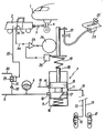
En référence à la figure, le dispositif selon l'invention est destiné à assurer le freinage au remorquage d'un avion 1 au sol entraîné par un véhicule tracteur 2 relié mécaniquement à l'avion 1, par exemple au moyen d'une barre de remorquage 3 convenablement fixée au train avant 4 de l'avion 1.Referring to the figure, the device according to the invention is intended to ensure braking when towing an airplane 1 on the ground driven by a
Dans le mode de réalisation préféré illustré, le dispositif de freinage au remorquage est associé au circuit de freinage de parking de l'avion. Ce circuit de freinage de parking comporte une ligne d'alimentation 5 reliée à une pompe d'alimentation non représentée du circuit de freinage lorsque les moteurs de l'avion sont en service. Un accumulateur hydraulique 6 est relié à la canalisation d'alimentation 5 et permet d'exécuter un certain nombre de manoeuvres de freinage lorsque les pompes d'alimentation habituelles sont hors service. Le circuit de freinage de parking comporte en outre de façon classique un organe de freinage, généralement désigné en 7, formé par un distributeur comportant un piston différentiel 8 à deux étages coulissant dans un boîtier 9 ayant une entrée 10 reliée à la canalisation d'alimentation 5, une sortie 11 reliée à des freins de roues 12 par des tronçons de canalisation 13 et une seconde sortie 14 reliée à une canalisation de retour 15. Le piston 8 est soumis à l'action d'un ressort 16 agissant dans le sens d'une coupure de l'alimentation en fluide de freinage et d'une liaison entre le tronçon de canalisation 11 et la canalisation de retour 15. Un orifice calibré 17 relie l'espace intermédiaire du piston différentiel 8 avec la face extrême tournée vers le ressort de rappel 16. Le piston 8 est relié à une tige de piston 18 sur laquelle prend appui l'extrémité d'un ressort de manoeuvre 19 lui-même plus ou moins comprimé par une tige de manoeuvre 20 entraînée par un câble de manoeuvre 21 associé à une manette de commande de frein de parking 22 par l'intermédiaire d'un boîtier de commande 23.In the preferred embodiment illustrated, the towing braking device is associated with the aircraft parking brake circuit. This parking braking circuit comprises a
Selon le mode de réalisation préféré de l'invention, un moteur électrique 24, par exemple un moteur électrique pas à pas est associé à la tige de manoeuvre 20 pour assurer le déplacement de celle-ci en parallèle au câble 21. Le moteur 24 est entraîné en rotation en réponse à des signaux provenant d'un comparateur 25 ayant une première entrée reliée par une ligne 34 à un organe d'émission de consigne 26 associé à la pédale de freinage 27 du véhicule tracteur 2 et une seconde entrée reliée à un détecteur de position 28 de la tige de manoeuvre 20, par exemple un détecteur de position potentiométrique associé à un curseur porté par la tige de manoeuvre 20.According to the preferred embodiment of the invention, an
De préférence, on prévoit également selon l'invention une pompe électrique 29 ayant un orifice d'admission relié à une réserve de fluide de freinage par l'intermédiaire d'un tronçon de canalisation 30 et un orifice de sortie relié à la canalisation d'alimentation 5 par l'intermédiaire d'un tronçon de canalisation 31 sur lequel est monté un clapet anti-retour 32. La pompe électrique 29 est reliée au véhicule tracteur 2 par une ligne d'alimentation électrique 33.Preferably, an electric pump 29 is also provided according to the invention having an inlet port connected to a reserve of brake fluid via a section of
Lorsque l'avion est en service, le circuit de freinage de parking est utilisé normalement en manoeuvrant la poignée de freinage de parking 22. Lorsque l'on souhaite remorquer l'avion au moyen d'un tracteur 2, on branche la ligne d'alimentation électrique 33 et l'on relie la première entrée du comparateur 25 à l'organe d'émission de consigne 26 du tracteur 2, puis on déplace la manette de commande 22 vers la position de débloquage des freins. Dans cette position, le distributeur 7 du circuit de freins de parking se trouve commandé par les signaux du comparateur 25 agissant sur le second moteur 24.When the aircraft is in service, the parking brake circuit is used normally by operating the
Bien entendu l'invention n'est pas limitée au mode de réalisation décrit et on peut y apporter des variantes de réalisation qui apparaîtront à l'homme de métier. En particulier, au lieu d'utiliser le distributeur du circuit de freinage de parking de l'avion, on peut agir sur un autre organe de freinage du circuit de freinage de l'avion ou prévoir de disposer un organe de freinage particulier dans ce circuit de freinage.Of course, the invention is not limited to the embodiment described and it is possible to make variant embodiments which will appear to those skilled in the art. In particular, instead of using the distributor of the aircraft parking brake circuit, it is possible to act on another braking member of the aircraft braking circuit or to provide for having a particular braking member in this circuit braking.
On peut également prévoir de remplacer la liaison électrique décrite entre le tracteur et l'avion par une liaison hydraulique, le circuit de freinage du tracteur 2 étant alors directement associé au circuit de freinage de l'avion. Une telle solution suppose toutefois que des précautions soient prises pour assurer une pureté suffisante du fluide de freinage utilisé sur le tracteur afin de ne pas risquer de polluer le circuit de freinage de l'avion lors d'une utilisation du dispositif de freinage au remorquage.It is also possible to provide for replacing the electrical connection described between the tractor and the airplane with a hydraulic connection, the braking circuit of the
Bien que selon l'invention il soit préféré d'incorporer une pompe électrique 29, qui peut être de faible puissance, dans le circuit de freinage de l'avion afin d'assurer une pression suffisante du fluide de freinage dans ce circuit, on peut également prévoir d'utiliser les pompes d'alimentation habituelles de l'avion en entraînant celles-ci au moyen du groupe auxiliaire de puissance de l'avion.Although according to the invention it is preferred to incorporate an electric pump 29, which may be of low power, in the braking circuit of the aircraft in order to ensure sufficient pressure of the braking fluid in this circuit, it is possible to also plan to use the aircraft's usual fuel pumps by driving them by means of the aircraft's auxiliary power unit.
Claims (3)
Applications Claiming Priority (2)
| Application Number | Priority Date | Filing Date | Title |
|---|---|---|---|
| FR8618199 | 1986-12-26 | ||
| FR8618199A FR2608986B1 (en) | 1986-12-26 | 1986-12-26 | BRAKING DEVICE FOR TOWING AN AIRCRAFT ON THE GROUND |
Publications (2)
| Publication Number | Publication Date |
|---|---|
| EP0275787A1 EP0275787A1 (en) | 1988-07-27 |
| EP0275787B1 true EP0275787B1 (en) | 1990-08-08 |
Family
ID=9342314
Family Applications (1)
| Application Number | Title | Priority Date | Filing Date |
|---|---|---|---|
| EP87402974A Expired - Lifetime EP0275787B1 (en) | 1986-12-26 | 1987-12-23 | Brake device for use in towing an aeroplane on the ground |
Country Status (4)
| Country | Link |
|---|---|
| US (1) | US4976499A (en) |
| EP (1) | EP0275787B1 (en) |
| JP (1) | JPS63240498A (en) |
| FR (1) | FR2608986B1 (en) |
Cited By (1)
| Publication number | Priority date | Publication date | Assignee | Title |
|---|---|---|---|---|
| DE19931865A1 (en) * | 1999-07-09 | 2001-01-11 | Schopf Maschb Gmbh | Aircraft towing vehicle |
Families Citing this family (15)
| Publication number | Priority date | Publication date | Assignee | Title |
|---|---|---|---|---|
| DE4024894C2 (en) * | 1990-08-06 | 1997-05-22 | Krauss Maffei Ag | Aircraft towing vehicle |
| GB9207183D0 (en) * | 1992-04-01 | 1992-05-13 | Melnick Irving | Method and apparatus for moving aircraft |
| US20090014261A1 (en) * | 2006-08-29 | 2009-01-15 | Jonathan Sidney Edelson | Apparatus for controlling aircraft parking brakes |
| US8245980B2 (en) | 2006-09-28 | 2012-08-21 | Israel Aerospace Industries Ltd. | System and method for transferring airplanes |
| US8544792B2 (en) | 2006-09-28 | 2013-10-01 | Israel Aerospace Industries Ltd. | Towbarless airplane tug |
| US9403604B2 (en) | 2006-09-28 | 2016-08-02 | Israel Aerospace Industries Ltd. | System and method for transferring airplanes |
| US7975959B2 (en) * | 2006-09-28 | 2011-07-12 | Israel Aerospace Industries Ltd. | System and method for transferring airplanes |
| US9199745B2 (en) * | 2007-05-16 | 2015-12-01 | Israel Aerospace Industries Ltd. | System and method for transferring airplanes |
| IL198950A (en) | 2008-11-25 | 2013-01-31 | Israel Aerospace Ind Ltd | Towbarless airplane tug |
| CN102869573B (en) | 2010-02-16 | 2015-06-17 | 以色列宇航工业有限公司 | Plane tractor and method for using same to grab and pull plane |
| IL206061A0 (en) | 2010-05-30 | 2010-11-30 | Israel Aerospace Ind Ltd | Controller for a hydraulic drive system |
| IL206262A0 (en) | 2010-06-09 | 2011-02-28 | Raphael E Levy | System and method for transferring airplanes |
| EP2964525B1 (en) * | 2013-03-06 | 2022-10-05 | Airbus Canada Limited Partnership | Parking brake control system for an aircraft |
| CN104803007A (en) * | 2015-03-31 | 2015-07-29 | 中国民航大学 | Intelligent speech recognition system of aircraft tractor |
| US10093296B2 (en) | 2017-01-25 | 2018-10-09 | Goodrich Corporation | Electrically activated park and emergency valve with on-valve manual actuation feature |
Citations (1)
| Publication number | Priority date | Publication date | Assignee | Title |
|---|---|---|---|---|
| US4007890A (en) * | 1975-09-30 | 1977-02-15 | The Boeing Company | Aircraft towing braking system |
Family Cites Families (12)
| Publication number | Priority date | Publication date | Assignee | Title |
|---|---|---|---|---|
| FR951343A (en) * | 1942-01-06 | 1949-10-21 | Westinghouse Air Brake Co | Pressurized brake enhancements |
| US2365557A (en) * | 1942-08-06 | 1944-12-19 | Keith Glenn | Multiple means for applying brakes |
| US3048976A (en) * | 1958-08-25 | 1962-08-14 | John D Grigsby | Brake control system |
| US3034598A (en) * | 1960-07-11 | 1962-05-15 | Goodyear Tire & Rubber | Tractor-trailer brake combination |
| US3350142A (en) * | 1965-02-08 | 1967-10-31 | Midland Ross Corp | Actuator system |
| FR1490557A (en) * | 1966-05-04 | 1967-08-04 | Citroen Sa Andre | Improvements to braking devices for articulated vehicles |
| DE1506001A1 (en) * | 1966-08-26 | 1969-07-24 | Dornier Reparaturwerft Gmbh | Towing device for aircraft with hydraulic braking system |
| DE2404519C2 (en) * | 1974-01-31 | 1986-02-20 | Robert Bosch Gmbh, 7000 Stuttgart | Hydraulic braking system for a towing vehicle with a trailer |
| SE411736B (en) * | 1974-06-15 | 1980-02-04 | Birkeholm Mogens | PROCEDURE AND DEVICE FOR TOWING A VEHICLE, EXAMPLE OF AN AIRPLANE |
| AU512993B2 (en) * | 1976-03-25 | 1980-11-06 | Bull J L | Towed vehicle brake |
| US4056286A (en) * | 1976-06-08 | 1977-11-01 | Westinghouse Air Brake Company | Remote control brake system for a railway train |
| US4635758A (en) * | 1985-06-19 | 1987-01-13 | Beard Jr Frank A | Hydraulic control system for simultaneous application of brakes of towing and towed vehicles with equal intensity |
-
1986
- 1986-12-26 FR FR8618199A patent/FR2608986B1/en not_active Expired - Lifetime
-
1987
- 1987-12-23 EP EP87402974A patent/EP0275787B1/en not_active Expired - Lifetime
- 1987-12-25 JP JP62327532A patent/JPS63240498A/en active Granted
-
1989
- 1989-12-06 US US07/449,306 patent/US4976499A/en not_active Expired - Lifetime
Patent Citations (1)
| Publication number | Priority date | Publication date | Assignee | Title |
|---|---|---|---|---|
| US4007890A (en) * | 1975-09-30 | 1977-02-15 | The Boeing Company | Aircraft towing braking system |
Cited By (1)
| Publication number | Priority date | Publication date | Assignee | Title |
|---|---|---|---|---|
| DE19931865A1 (en) * | 1999-07-09 | 2001-01-11 | Schopf Maschb Gmbh | Aircraft towing vehicle |
Also Published As
| Publication number | Publication date |
|---|---|
| FR2608986A1 (en) | 1988-07-01 |
| JPH0573622B2 (en) | 1993-10-14 |
| JPS63240498A (en) | 1988-10-06 |
| EP0275787A1 (en) | 1988-07-27 |
| FR2608986B1 (en) | 1990-11-30 |
| US4976499A (en) | 1990-12-11 |
Similar Documents
| Publication | Publication Date | Title |
|---|---|---|
| EP0275787B1 (en) | Brake device for use in towing an aeroplane on the ground | |
| CA2500842C (en) | Longitudinal piloting system of a taxiing aircraft | |
| FR2569381A1 (en) | CIRCUIT ARRANGEMENT FOR CONTROLLING A CLUTCH OF A MOTOR VEHICLE | |
| FR2474717A1 (en) | SPEED CONTROL OF AN ENGINE | |
| EP1205369A1 (en) | Architecture of a hydraulic brake system for an aircraft | |
| FR2579945A1 (en) | ||
| EP1107897B1 (en) | Braking device with combined power-assistance and control | |
| WO2009141550A2 (en) | Ancillary device for taxiing along the ground an aircraft with an air turbine | |
| EP0928740A1 (en) | Brake device for a set of aircraft wheels | |
| EP1160157B1 (en) | Fly-by-wire aircraft with autopilot | |
| EP0334723A1 (en) | Control device for a hydraulic double-acting actuator | |
| EP1026565A1 (en) | Yaw control system for an aircraft | |
| FR2576261A1 (en) | BRAKE PRESSURE GENERATOR FOR MOTOR VEHICLE | |
| FR2769284A1 (en) | Control device of helicopter tail rotor aerodynamic steering surface | |
| EP3578459A1 (en) | Aircraft landing gear with adjustable lower portion and simplified directing device | |
| CA3065871C (en) | Control device for undercarriage motorization | |
| FR2669883A1 (en) | AUTOMATIC BRAKING DEVICE FOR VEHICLE. | |
| EP0410891B1 (en) | Hydraulic brake circuit | |
| CA1279682C (en) | Braking device for airplane being towed on an apron | |
| FR3060528A1 (en) | DEVICE FOR CONTROLLING MOBILE SURFACES AND A WHEEL DIRECTOR OF AN AIRCRAFT | |
| FR2658475A1 (en) | VEHICLE WITH ELEVATOR CAB. | |
| FR2544973A1 (en) | Improvements to swivelling driving seats, in particular for forestry vehicles | |
| EP0637536B1 (en) | Transmission and control unit with dual input and its application in a working vehicle with two steering locations | |
| EP0054500B1 (en) | Hydraulic driving device for a tractor-coupled semi-trailer | |
| EP1029761B1 (en) | Braking system for a motor vehicle with hydro-pneumatic suspension |
Legal Events
| Date | Code | Title | Description |
|---|---|---|---|
| PUAI | Public reference made under article 153(3) epc to a published international application that has entered the european phase |
Free format text: ORIGINAL CODE: 0009012 |
|
| 17P | Request for examination filed |
Effective date: 19871224 |
|
| AK | Designated contracting states |
Kind code of ref document: A1 Designated state(s): GB SE |
|
| 17Q | First examination report despatched |
Effective date: 19890517 |
|
| GRAA | (expected) grant |
Free format text: ORIGINAL CODE: 0009210 |
|
| AK | Designated contracting states |
Kind code of ref document: B1 Designated state(s): GB SE |
|
| GBT | Gb: translation of ep patent filed (gb section 77(6)(a)/1977) | ||
| PLBE | No opposition filed within time limit |
Free format text: ORIGINAL CODE: 0009261 |
|
| STAA | Information on the status of an ep patent application or granted ep patent |
Free format text: STATUS: NO OPPOSITION FILED WITHIN TIME LIMIT |
|
| 26N | No opposition filed | ||
| EAL | Se: european patent in force in sweden |
Ref document number: 87402974.7 |
|
| PGFP | Annual fee paid to national office [announced via postgrant information from national office to epo] |
Ref country code: SE Payment date: 19951218 Year of fee payment: 9 |
|
| PG25 | Lapsed in a contracting state [announced via postgrant information from national office to epo] |
Ref country code: SE Effective date: 19961224 |
|
| EUG | Se: european patent has lapsed |
Ref document number: 87402974.7 |
|
| REG | Reference to a national code |
Ref country code: GB Ref legal event code: IF02 |
|
| PGFP | Annual fee paid to national office [announced via postgrant information from national office to epo] |
Ref country code: GB Payment date: 20061222 Year of fee payment: 20 |
|
| REG | Reference to a national code |
Ref country code: GB Ref legal event code: PE20 |
|
| PG25 | Lapsed in a contracting state [announced via postgrant information from national office to epo] |
Ref country code: GB Free format text: LAPSE BECAUSE OF EXPIRATION OF PROTECTION Effective date: 20071222 |