EP0275511A1 - A process and device for measuring and processing the displacements between two or more points in structures, buildings, machinery or the like - Google Patents
A process and device for measuring and processing the displacements between two or more points in structures, buildings, machinery or the like Download PDFInfo
- Publication number
- EP0275511A1 EP0275511A1 EP87118824A EP87118824A EP0275511A1 EP 0275511 A1 EP0275511 A1 EP 0275511A1 EP 87118824 A EP87118824 A EP 87118824A EP 87118824 A EP87118824 A EP 87118824A EP 0275511 A1 EP0275511 A1 EP 0275511A1
- Authority
- EP
- European Patent Office
- Prior art keywords
- targets
- laser
- prism
- photodetector
- points
- Prior art date
- Legal status (The legal status is an assumption and is not a legal conclusion. Google has not performed a legal analysis and makes no representation as to the accuracy of the status listed.)
- Withdrawn
Links
- 238000000034 method Methods 0.000 title claims abstract description 22
- 238000012545 processing Methods 0.000 title claims abstract description 7
- 238000006073 displacement reaction Methods 0.000 title 1
- 230000000694 effects Effects 0.000 claims description 6
- 230000003245 working effect Effects 0.000 claims description 6
- 230000001143 conditioned effect Effects 0.000 claims 2
- 238000005259 measurement Methods 0.000 description 4
- 238000011161 development Methods 0.000 description 2
- 238000009434 installation Methods 0.000 description 2
- 239000007788 liquid Substances 0.000 description 2
- 238000007596 consolidation process Methods 0.000 description 1
- 238000001514 detection method Methods 0.000 description 1
- 238000010586 diagram Methods 0.000 description 1
- CPBQJMYROZQQJC-UHFFFAOYSA-N helium neon Chemical compound [He].[Ne] CPBQJMYROZQQJC-UHFFFAOYSA-N 0.000 description 1
- 238000002347 injection Methods 0.000 description 1
- 239000007924 injection Substances 0.000 description 1
- 230000003902 lesion Effects 0.000 description 1
Images
Classifications
-
- G—PHYSICS
- G01—MEASURING; TESTING
- G01C—MEASURING DISTANCES, LEVELS OR BEARINGS; SURVEYING; NAVIGATION; GYROSCOPIC INSTRUMENTS; PHOTOGRAMMETRY OR VIDEOGRAMMETRY
- G01C15/00—Surveying instruments or accessories not provided for in groups G01C1/00 - G01C13/00
- G01C15/002—Active optical surveying means
- G01C15/004—Reference lines, planes or sectors
Definitions
- the present invention concerns a process and a device for the measurement and processing in real time of the level changes which may occur between two or more points in a structure, building, machinery or the like, specially during works of civil engineering directly or indirectly involving the same.
- Typical examples of said applications can be found in tunnel workings, where phenomena of surface draw can take place related to the changes in the ground tensive state, in particular changes induced during works of injection and/or consolidation.
- the importance of such draws obviously varies in proportion to the distance of the considered points from the tunnel and to several other factors; in urban areas, in any case, said distance is necessarily reduced and therefore there is the need of controlling the effects that said draws have on the buildings located near the tunnel, as the distortions caused may involve structural lesions of considerable importance and even affect the stability of the buildings themselves.
- the same types of draws can affect the correct positioning of machinery, for instance digging machines.
- a possible control consists in using techniques which optimize the operative modes of said workings, but said techniques present a too high degree of approximation, mainly in urban areas, and therefore cannot represent a sufficiently valid method for controlling said phenomena.
- communicating vessel level meters allow the continuous measurement of differential changes of level in a number of points or stations, between one another or with respect to the level of one station taken as a reference point.
- the disadvantage of said system lies in the fact that, as indicated by its name, it works according to the principle of the communicating vessels; the system therefore needs a certain number of vessels (one for each station) which must be closed and provided with instruments, partially filled with a liquid and communicating by means of a double connection (liquid side and gas side), as obtained by one or more ducts which must be installed horizontally or, when this is not possible, must be provided with special devices compensating the non horizontal development of the system.
- the resulting system is consequently rigid and complicated, and its extremely difficult installation makes the use thereof not suitable for limited periods of time, such as those involved during urban workings.
- An object of the present invention is therefore to solve the above mentioned problems by providing a process and a device for measuring in real time the differential changes of level between two or more points in a building, machinery or structure undergoing the effects caused by workings of civil engineering.
- the present invention relates to a process for measuring in real time the differential changes between two or more predetermined points in a building, structure, machinery or the like, in particular when submitted to the effects of works of civil engineering, said process being based on the use of a laser ray and characterized in that it comprises the steps of: positioning a laser tube and a rotating prism assembled on a motor; generating a laser ray; refracting said laser ray by means of said rotating prism to move it along an arc, on a planar or conical surface, as far as to hit in sequence one or more targets located in predetermined points of the work or the like; detecting the position of the interception point of the rotating laser ray on each one of said targets; obtaining a signal proportional to the position of the interception point with respect to a reference level on each target and processing the data obtained according to present modes and standards.
- the invention relates to a device for measuring in real time the differential changes of level between two or more points or stations in a building, structure, machinery or the like, specially if undergoing the effects of workings of civil engineering, of the type using a laser level meter, characterized in that it comprises a source of laser light, a rotating prism, several targets made integral with said points or stations, one or more signal conditioners/amplifiers provided by the targets because of the impact on them of the laser ray, and at least a computer for storing and processing the obtained signals.
- the laser level meters presently known essentially consist in a laser, a receiver and a control panel and are generally applied in agriculture, in the preparation of rice-fields which must present an optimal inclination.
- This type of application however operates on one target which is moved in the field and does not envisage to simultaneously perform several detections on several fixed targets by means of a single laser.
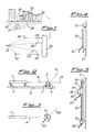
- a device 30, consisting of a laser tube and a rotating prism, is positioned in a way as to "see” a series of targets 32 fixed for instance to the walls of buildings located in the area involved by the digging work of a tunnel 31.
- the targets 32 when hit by the laser ray, emit a signal which is sent, by means of connecting devices 34, to a computer 36, which may be common to all targets.
- a laser tube 1 for instance a gas tube of the Helium-Neon type (He-Ne), is fixed to a base 2 by means of micrometer screws 3, which are used for adijusting the position of the tube itself.
- He-Ne Helium-Neon type
- a prism 5 assembled on a motor 6 which is on its turn housed on a support 7 allowing to adjust in a micrometric way the position of the axis of prism 5 and the inclination of its rotation axis with respect to the vertical.
- the motor 6 rotates the prism 5 by an angle of 360 degrees or less, at a speed which is preferably low (for example less than 60 r.p.m.), but can be also high (for example exceeding 3000 r.p.m.).
- the ray 4, passing through the rotating prism 5, is then refracted and "sweeps" a surface that can be the surface of a plane 8 or of a cone 9, according to the prism inclination.
- the ray rotating on the planar surface 8 or conical surface 9 hits in sequence the targets which have been previously arranged in predetermined positions.
- the speed of the rotating ray (namely the speed at which the prism 5 is rotated) is preferably not high, but also a high speed of the ray trasfer from one target to the subsequent one and a reduced speed of the ray "passage" on the target can also advantageously be used.
- the targets essentially consist each of a photodetector mounted on a support and can be of the fixed type (diagrammatically shown in figure 4) or of the mobile type (figure 5).
- a fixed screen 23 is envisaged, formed by a cylindrical surface provided with a number of openings for the passage of the ray 4 coming from the tube 1 and for the passage of the ray 8 or 9 directed to the targets.
- the surface presents for instance mobile plates which are removed in correspondence to the alignments with the tube 1 and the targets.
- the target of fixed type includes a support 10 which can be bonded for instance to the wall 11 of a building; the support 10 bears a photodetector 12, preferably of the continuous type with position cells on a sigle axis, such as for example the photodetectors of the series "LSC" manufactured by United Detector Technology.
- a photodetector 12 preferably of the continuous type with position cells on a sigle axis, such as for example the photodetectors of the series "LSC" manufactured by United Detector Technology.
- a local yielding of the building causes a level variation of at least one of the photodetectors 12 and therefore a change in the signal sent to the computer which processes and possibly visualizes said change by means of a printer and/or a monitor or the like.
- this variation specially when compared with that of nearby targets, exceeds a preset level of danger, an alarm system is activated.
- the target of mobile type (figure 5) consists of a support 14, to be fixed for example to the wall 11 of a building, on which a worm screw 15 is mounted and is operated by a motor 16.
- the screw 15 moves a support 17 which bears a central photodetector 18, a maximum photodetector 19 and a minimum photodetector 20.
- the device and the process described allow therefore to obtain in real time the measurement of the change of level in a number of points or stations with respect to a point or station taken as reference and/or with respect to each other, in an extremely simple manner, thus providing a flexible and easy to use system for the control of yieldings in civil or industrial buildings, in machinery supports or the like.
Landscapes
- Physics & Mathematics (AREA)
- Engineering & Computer Science (AREA)
- General Physics & Mathematics (AREA)
- Radar, Positioning & Navigation (AREA)
- Remote Sensing (AREA)
- Length Measuring Devices By Optical Means (AREA)
Abstract
A process and device for measuring and processing in real time the changes of level between two or more points in buildings, structures, machinery or the like, when interested by works of civil engineering, wherein a laser ray generated by a laser tube and rotated on a planar or conical surface hits one or more targets constituted by fixed or mobile photodetectors, said targets being placed in correspondence with said points. The signals generated by the targets are transferred to a computer to be processed and immediately read.
Description
- The present invention concerns a process and a device for the measurement and processing in real time of the level changes which may occur between two or more points in a structure, building, machinery or the like, specially during works of civil engineering directly or indirectly involving the same. Typical examples of said applications can be found in tunnel workings, where phenomena of surface draw can take place related to the changes in the ground tensive state, in particular changes induced during works of injection and/or consolidation. The importance of such draws obviously varies in proportion to the distance of the considered points from the tunnel and to several other factors; in urban areas, in any case, said distance is necessarily reduced and therefore there is the need of controlling the effects that said draws have on the buildings located near the tunnel, as the distortions caused may involve structural lesions of considerable importance and even affect the stability of the buildings themselves. The same types of draws can affect the correct positioning of machinery, for instance digging machines.
- A possible control consists in using techniques which optimize the operative modes of said workings, but said techniques present a too high degree of approximation, mainly in urban areas, and therefore cannot represent a sufficiently valid method for controlling said phenomena.
- It is therefore necessary to find a system for controlling and measuring in real time said draw, in order to allow to take in due time the appropriate measures. For this reason, and in any case to maintain the control on the conditions of buildings or machinery during digging operations, as well as for other applications in civil engineering field, so-called communicating vessel level meters are used. Said communicating vessel level meters allow the continuous measurement of differential changes of level in a number of points or stations, between one another or with respect to the level of one station taken as a reference point. The disadvantage of said system lies in the fact that, as indicated by its name, it works according to the principle of the communicating vessels; the system therefore needs a certain number of vessels (one for each station) which must be closed and provided with instruments, partially filled with a liquid and communicating by means of a double connection (liquid side and gas side), as obtained by one or more ducts which must be installed horizontally or, when this is not possible, must be provided with special devices compensating the non horizontal development of the system. The resulting system is consequently rigid and complicated, and its extremely difficult installation makes the use thereof not suitable for limited periods of time, such as those involved during urban workings.
- So there still is the need of a system for the continuuous measurement in time of the differential changes of level between two or more points, which is flexible and of easy installation. Said need is made even more urgent by the impulse recently given to the development of underground transport in large urban areas.
- An object of the present invention is therefore to solve the above mentioned problems by providing a process and a device for measuring in real time the differential changes of level between two or more points in a building, machinery or structure undergoing the effects caused by workings of civil engineering.
- Accordingly, the present invention relates to a process for measuring in real time the differential changes between two or more predetermined points in a building, structure, machinery or the like, in particular when submitted to the effects of works of civil engineering, said process being based on the use of a laser ray and characterized in that it comprises the steps of: positioning a laser tube and a rotating prism assembled on a motor; generating a laser ray; refracting said laser ray by means of said rotating prism to move it along an arc, on a planar or conical surface, as far as to hit in sequence one or more targets located in predetermined points of the work or the like; detecting the position of the interception point of the rotating laser ray on each one of said targets; obtaining a signal proportional to the position of the interception point with respect to a reference level on each target and processing the data obtained according to present modes and standards. Furthermore, the invention relates to a device for measuring in real time the differential changes of level between two or more points or stations in a building, structure, machinery or the like, specially if undergoing the effects of workings of civil engineering, of the type using a laser level meter, characterized in that it comprises a source of laser light, a rotating prism, several targets made integral with said points or stations, one or more signal conditioners/amplifiers provided by the targets because of the impact on them of the laser ray, and at least a computer for storing and processing the obtained signals.
- It must be noticed that the laser level meters presently known essentially consist in a laser, a receiver and a control panel and are generally applied in agriculture, in the preparation of rice-fields which must present an optimal inclination. This type of application however operates on one target which is moved in the field and does not envisage to simultaneously perform several detections on several fixed targets by means of a single laser.
- The invention will be now described more in detail with reference to the accompanying drawings which are given for illustrative and not limiting purpose and wherein:
- - figure 1 is a general diagram showing the operation of a differential level detecting device according to the invention;
- - figure 2 is a side view of the laser ray emission and refraction unit, which is part of the device of figure 1;
- - figure 3 is a view from the top of the lase ray emission and refraction unit;
- - figure 4 is a cross-sectional view of a fixed type target;
- - figure 5 in a cross-sectional view of a mobile type target.
- In the scheme of figure 1, a
device 30, consisting of a laser tube and a rotating prism, is positioned in a way as to "see" a series oftargets 32 fixed for instance to the walls of buildings located in the area involved by the digging work of atunnel 31. - The
targets 32, when hit by the laser ray, emit a signal which is sent, by means of connectingdevices 34, to acomputer 36, which may be common to all targets. - With reference to figures 2 and 3, a laser tube 1, for instance a gas tube of the Helium-Neon type (He-Ne), is fixed to a base 2 by means of micrometer screws 3, which are used for adijusting the position of the tube itself.
- In front of the tube 1, on the side where the laser ray 4 comes out, there is a
prism 5 assembled on amotor 6 which is on its turn housed on a support 7 allowing to adjust in a micrometric way the position of the axis ofprism 5 and the inclination of its rotation axis with respect to the vertical. - The
motor 6 rotates theprism 5 by an angle of 360 degrees or less, at a speed which is preferably low (for example less than 60 r.p.m.), but can be also high (for example exceeding 3000 r.p.m.). The ray 4, passing through therotating prism 5, is then refracted and "sweeps" a surface that can be the surface of a plane 8 or of a cone 9, according to the prism inclination. - The ray rotating on the planar surface 8 or conical surface 9 hits in sequence the targets which have been previously arranged in predetermined positions. The speed of the rotating ray (namely the speed at which the
prism 5 is rotated) is preferably not high, but also a high speed of the ray trasfer from one target to the subsequent one and a reduced speed of the ray "passage" on the target can also advantageously be used. The targets essentially consist each of a photodetector mounted on a support and can be of the fixed type (diagrammatically shown in figure 4) or of the mobile type (figure 5). Preferably, around therotating prism 5, a fixed screen 23 is envisaged, formed by a cylindrical surface provided with a number of openings for the passage of the ray 4 coming from the tube 1 and for the passage of the ray 8 or 9 directed to the targets. The surface presents for instance mobile plates which are removed in correspondence to the alignments with the tube 1 and the targets. - The target of fixed type (figure 4) includes a
support 10 which can be bonded for instance to thewall 11 of a building; thesupport 10 bears aphotodetector 12, preferably of the continuous type with position cells on a sigle axis, such as for example the photodetectors of the series "LSC" manufactured by United Detector Technology. When the laser ray hits thephotodetector 12, it generates a signal which is a function of the distance of the impact point from the end contacts of the photodetector. Said signal is sent through one ormore cables 13, or by radio, to a conditioner/amplifier and then to a computer (not shown) which processes and possibly visualizes said signal, together with other similar signals, for their immediate reading. A local yielding of the building causes a level variation of at least one of thephotodetectors 12 and therefore a change in the signal sent to the computer which processes and possibly visualizes said change by means of a printer and/or a monitor or the like. In case this variation, specially when compared with that of nearby targets, exceeds a preset level of danger, an alarm system is activated. - The target of mobile type (figure 5) consists of a
support 14, to be fixed for example to thewall 11 of a building, on which aworm screw 15 is mounted and is operated by amotor 16. Thescrew 15 moves asupport 17 which bears acentral photodetector 18, amaximum photodetector 19 and aminimum photodetector 20. - According to what is photodetector hit by the laser ray, different signals are generated. When the ray 8 hits the
photodetector motor 16 until thephotodetector 18 is again at the height of the surface covered by the ray and themotor 16 generates on its turn signals which are sent throughcables 22 or by radio to said conditioner/amplifier (not shown) and then to a computer which processes and possibly visualizes said signals by means of a monitor, a printer and the like. The device and the process described allow therefore to obtain in real time the measurement of the change of level in a number of points or stations with respect to a point or station taken as reference and/or with respect to each other, in an extremely simple manner, thus providing a flexible and easy to use system for the control of yieldings in civil or industrial buildings, in machinery supports or the like.
Claims (15)
1. A process for measuring in real time the differential changes of position between two or more predetermined points or stations in a building, machinery, structure or the like, in particular undergoing the effects of works of civil engineering, by using a laser ray, characterized in that it comprises the steps of: positioning a laser tube and a rotating prism mounted on a motor; generating a laser ray; refracting the laser ray by means of said rotating prism to move it along an arc, on a planar or conical surface, as far as to hit in sequence a number of targets located in correspondence with said stations in the building or the like; detecting the position of the interception point of the rotating laser ray on each one of said targets; obtaining a signal proportional to the position of the interception point with respect to one reference position on each target; and processing the data obtained according to present methods and standards.
2. A process according to claim 1, characterized in that the laser ray refracted by the rotating prism is screened along the arc of the prism rotation, except in points aligned with the targets.
3. A process according to claim 1 or 2, characterized in that the prism is positioned by adjusting the inclination of its rotation axis with respect to the vertical.
4. A process according to claim 1, characterized in that the prism is rotated at a speed below 60 r.p.m.
5. A process according to claim 1, characterized in that the prism is rotated at a speed of a least 3000 r.p.m.
6. A process according to one of the claims 1 to 5, characterized in that the signal generated by the laser ray on each target is conditioned, amplified and sent to a computer which is common to all targets, sait targets being in the form of photodetectors.
7. A process according to claim 6, characterized in that the signal generated by the laser ray on each photodetector actuates, through a computer, a mechanical device for adjusting the position in height of the same photodetector.
8. A process according to claim 7, characterized in that the adjustment in height of the photodetector position generates a signal which is conditioned, amplified and sent to a computer.
9. A device for measuring in real time the differential changes of position between two or more points or stations in a building, structure, machinery or the like, specially undergoing the effects of civil engineering workings, of the type using a laser level meter, characterized in that it comprises: a source of laser light; a rotating prism; several targets made integral with said points or stations; one or more conditioners/amplifiers of signals provided by the targets after the impact on them of a laser ray; and at least a computer for storing and processing said signals.
10. A device according to claim 9, characterized in that said source of laser light is a laser tube mounted on micrometer screws for position adjustment.
11. A device according to claim 9, characterized in that said prism is mounted on a motor rotating at slow speed (10-30 r.p.m.) or at a high speed (at least 3000 r.p.m.).
12. A device according to one of the claims 9 to 11, characterized in that the prism is surrounded by a screen wherein openings are provided in corrispondence with the alignments with the laser tube and the targets.
13. A device according to claim 9, characterized in that the targets consist of fixed photodetectors of the continuous type with position cells, mounted along an axis and generating a signal which is a function of the distance of the impact point of the laser ray from the photodetector ends.
14. A device according to claim 9, characterized in that the targets consist of mobile photodetectors including a central photodetector, a maximum photodetector and a minimum photodetector, all mounted on a support which is movable along a worm screw.
15. A device according to claim 14, characterized in that the worm screw is connected to a motor actuated by said computer on the basis of signals provided by one of said photodetectors.
Applications Claiming Priority (2)
| Application Number | Priority Date | Filing Date | Title |
|---|---|---|---|
| IT2283286 | 1986-12-23 | ||
| IT22832/86A IT1205317B (en) | 1986-12-23 | 1986-12-23 | PROCEDURE AND DEVICE FOR THE MEASUREMENT AND PROCESSING OF MOVEMENTS BETWEEN TWO OR MORE IN STRUCTURES, BUILDINGS, MACHINERY OR SIMILAR |
Publications (1)
| Publication Number | Publication Date |
|---|---|
| EP0275511A1 true EP0275511A1 (en) | 1988-07-27 |
Family
ID=11200962
Family Applications (1)
| Application Number | Title | Priority Date | Filing Date |
|---|---|---|---|
| EP87118824A Withdrawn EP0275511A1 (en) | 1986-12-23 | 1987-12-18 | A process and device for measuring and processing the displacements between two or more points in structures, buildings, machinery or the like |
Country Status (3)
| Country | Link |
|---|---|
| US (1) | US4889997A (en) |
| EP (1) | EP0275511A1 (en) |
| IT (1) | IT1205317B (en) |
Cited By (5)
| Publication number | Priority date | Publication date | Assignee | Title |
|---|---|---|---|---|
| GB2296323A (en) * | 1994-12-23 | 1996-06-26 | Monitoring Sys Ltd | Monitoring vertical movement of structures |
| EP0859215A4 (en) * | 1996-08-30 | 1998-09-30 | ||
| EP0962747A3 (en) * | 1998-06-01 | 2000-05-17 | Demetrio Federico | Remote control automated theodolite |
| EP1632749A1 (en) * | 2004-09-07 | 2006-03-08 | Bouygues Travaux Publics | Method and device for controlling the digging of an elongated excavation in a terrain. |
| WO2014166738A1 (en) * | 2013-04-08 | 2014-10-16 | Peri Gmbh | Formwork system for producing a concrete ceiling |
Families Citing this family (12)
| Publication number | Priority date | Publication date | Assignee | Title |
|---|---|---|---|---|
| DE4039881C2 (en) * | 1990-12-13 | 1997-04-30 | Hofmann Werkstatt Technik | Method and device for optically measuring an angle which wheel positions on vehicles form relative to one another |
| US5404132A (en) * | 1994-03-14 | 1995-04-04 | Canty; Jeffery N. | Deflection monitoring system |
| US5642297A (en) * | 1994-12-12 | 1997-06-24 | Gurley Precision Instruments, Inc. | Apparatus and method for measuring the kinematic accuracy in machines and mechanisms using absolute encoders |
| US5657003A (en) * | 1996-02-26 | 1997-08-12 | Fuentes; Alfredo | Structure movement monitoring and emergency alarm system |
| US5850185A (en) * | 1996-04-03 | 1998-12-15 | Canty; Jeffery N. | Deflection monitoring system |
| US6240783B1 (en) * | 1998-05-02 | 2001-06-05 | Usbi, Co | Bridge monitoring system |
| FR2843797B1 (en) * | 2002-08-23 | 2004-12-10 | Soldata | A SYSTEM FOR MONITORING THE MOVEMENTS OF WORKING PARTS |
| US7392592B2 (en) * | 2005-10-07 | 2008-07-01 | Milwaukee Electric Tool Corporation | Ruggedized laser level |
| US8020271B2 (en) * | 2007-07-11 | 2011-09-20 | Norton Baum | Self-raising form control system and method |
| CN102620673A (en) * | 2012-03-16 | 2012-08-01 | 同济大学 | Tunnel deformation online monitoring system based on image analysis and application of system |
| CN103604425B (en) * | 2013-11-22 | 2015-11-25 | 山东大学 | A kind of device for tunnel layout of the monitoring points and method of operating thereof |
| CN113865499B (en) * | 2021-09-16 | 2024-04-02 | 中建八局第一建设有限公司 | High formwork deformation monitoring device and method based on infrared point location projection |
Citations (4)
| Publication number | Priority date | Publication date | Assignee | Title |
|---|---|---|---|---|
| US3469919A (en) * | 1965-07-14 | 1969-09-30 | Floyd L Zellner | Electronic surveying instrument |
| FR2133176A5 (en) * | 1971-04-09 | 1972-11-24 | Comp Generale Electricite | |
| FR2135027A1 (en) * | 1971-03-29 | 1972-12-15 | Cilas | |
| EP0046647A2 (en) * | 1980-08-21 | 1982-03-03 | Idc Group Limited | Digital measuring device |
Family Cites Families (2)
| Publication number | Priority date | Publication date | Assignee | Title |
|---|---|---|---|---|
| US3822943A (en) * | 1973-02-28 | 1974-07-09 | New Hampshire Ball Bearings | Apparatus for establishing a visible plane or fan of light |
| US4674870A (en) * | 1985-10-18 | 1987-06-23 | Spectra-Physics, Inc. | Laser alignment system with modulated field |
-
1986
- 1986-12-23 IT IT22832/86A patent/IT1205317B/en active
-
1987
- 1987-12-18 EP EP87118824A patent/EP0275511A1/en not_active Withdrawn
- 1987-12-21 US US07/135,828 patent/US4889997A/en not_active Expired - Fee Related
Patent Citations (4)
| Publication number | Priority date | Publication date | Assignee | Title |
|---|---|---|---|---|
| US3469919A (en) * | 1965-07-14 | 1969-09-30 | Floyd L Zellner | Electronic surveying instrument |
| FR2135027A1 (en) * | 1971-03-29 | 1972-12-15 | Cilas | |
| FR2133176A5 (en) * | 1971-04-09 | 1972-11-24 | Comp Generale Electricite | |
| EP0046647A2 (en) * | 1980-08-21 | 1982-03-03 | Idc Group Limited | Digital measuring device |
Cited By (7)
| Publication number | Priority date | Publication date | Assignee | Title |
|---|---|---|---|---|
| GB2296323A (en) * | 1994-12-23 | 1996-06-26 | Monitoring Sys Ltd | Monitoring vertical movement of structures |
| EP0859215A4 (en) * | 1996-08-30 | 1998-09-30 | ||
| EP0962747A3 (en) * | 1998-06-01 | 2000-05-17 | Demetrio Federico | Remote control automated theodolite |
| EP1632749A1 (en) * | 2004-09-07 | 2006-03-08 | Bouygues Travaux Publics | Method and device for controlling the digging of an elongated excavation in a terrain. |
| FR2875015A1 (en) * | 2004-09-07 | 2006-03-10 | Bouygues Travaux Publics Sa | METHOD AND DEVICE FOR DETECTING THE POSSIBLE MOVEMENTS OF A GROUND CONSECUTIVE TO THE CREATION OF AN EXCAVATION EXTENDED IN THE FIELD |
| WO2006027498A1 (en) * | 2004-09-07 | 2006-03-16 | Bouygues Travaux Publics | Method and device for monitoring the digging of an elongated excavation in a ground |
| WO2014166738A1 (en) * | 2013-04-08 | 2014-10-16 | Peri Gmbh | Formwork system for producing a concrete ceiling |
Also Published As
| Publication number | Publication date |
|---|---|
| IT8622832A0 (en) | 1986-12-23 |
| US4889997A (en) | 1989-12-26 |
| IT1205317B (en) | 1989-03-15 |
Similar Documents
| Publication | Publication Date | Title |
|---|---|---|
| US4889997A (en) | Process and device for measuring and processing the displacements between two or more points in structures, buildings, machinery or the like | |
| US5055666A (en) | Surveying apparatus detecting relative angular position of projector and range finder | |
| US5784282A (en) | Method and apparatus for identifying the position in three dimensions of a movable object such as a sensor or a tool carried by a robot | |
| US5077557A (en) | Surveying instrument with receiver for satellite position-measuring system and method of operation | |
| EP0269283B1 (en) | Position sensing apparatus | |
| US3588255A (en) | Optical alignment methods and means utilizing coordinated laser beams and laser beam coordinating means for same | |
| EP0426287B1 (en) | Improved detection and display device | |
| EP0353968B1 (en) | Detection and display device | |
| JP2846950B2 (en) | Apparatus for forming or defining the position of a measuring point | |
| US3612700A (en) | Laser beam reference line means and method | |
| US4334775A (en) | Method for dynamically determining the horizontal motion and twist of a microwave tower | |
| JPS5825207B2 (en) | Device for setting each point and straight line | |
| US5189799A (en) | Laser goniometer | |
| CN106767926B (en) | Calibration method of digital calibration system of demarcation device | |
| CN210774020U (en) | Ceiling and ground levelness measuring device for project supervision | |
| US3560753A (en) | Method and apparatus for determining the displacement of a construction equipment guided along a desired course by a laser beam | |
| CN113884075A (en) | An intelligent display tunnel over-under-excavation projector and operation method | |
| GB2173369A (en) | Determining position | |
| CN112964191A (en) | Micro-deformation laser collimation measurement method | |
| CN107402035A (en) | Damping type support meanss for measuring instrument outdoor study | |
| US5721618A (en) | Apparatus for measuring the dimensions of large objects | |
| CN115507826B (en) | A measuring device and method for positioning an assembled guide wall | |
| GB2296323A (en) | Monitoring vertical movement of structures | |
| CN209230528U (en) | A kind of foundation pit enclosure structure deeply mixing cement-soil pile monitoring system | |
| JP3006379B2 (en) | Control device for slip form method |
Legal Events
| Date | Code | Title | Description |
|---|---|---|---|
| PUAI | Public reference made under article 153(3) epc to a published international application that has entered the european phase |
Free format text: ORIGINAL CODE: 0009012 |
|
| AK | Designated contracting states |
Kind code of ref document: A1 Designated state(s): AT BE CH DE ES FR GB GR IT LI NL SE |
|
| 17P | Request for examination filed |
Effective date: 19881229 |
|
| 17Q | First examination report despatched |
Effective date: 19900201 |
|
| STAA | Information on the status of an ep patent application or granted ep patent |
Free format text: STATUS: THE APPLICATION IS DEEMED TO BE WITHDRAWN |
|
| 18D | Application deemed to be withdrawn |
Effective date: 19920128 |