EP0275191B1 - Color cathode-ray tube having a three-lens electron gun - Google Patents
Color cathode-ray tube having a three-lens electron gun Download PDFInfo
- Publication number
- EP0275191B1 EP0275191B1 EP88300247A EP88300247A EP0275191B1 EP 0275191 B1 EP0275191 B1 EP 0275191B1 EP 88300247 A EP88300247 A EP 88300247A EP 88300247 A EP88300247 A EP 88300247A EP 0275191 B1 EP0275191 B1 EP 0275191B1
- Authority
- EP
- European Patent Office
- Prior art keywords
- electrode
- lens
- potential
- beams
- asymmetrically
- Prior art date
- Legal status (The legal status is an assumption and is not a legal conclusion. Google has not performed a legal analysis and makes no representation as to the accuracy of the status listed.)
- Expired - Lifetime
Links
- 238000010894 electron beam technology Methods 0.000 claims description 73
- 238000001125 extrusion Methods 0.000 claims description 12
- 230000004075 alteration Effects 0.000 description 4
- 230000000694 effects Effects 0.000 description 4
- 230000002093 peripheral effect Effects 0.000 description 4
- 238000007493 shaping process Methods 0.000 description 4
- OAICVXFJPJFONN-UHFFFAOYSA-N Phosphorus Chemical compound [P] OAICVXFJPJFONN-UHFFFAOYSA-N 0.000 description 3
- 238000010586 diagram Methods 0.000 description 3
- 230000008901 benefit Effects 0.000 description 2
- 239000011248 coating agent Substances 0.000 description 2
- 238000000576 coating method Methods 0.000 description 2
- 238000010276 construction Methods 0.000 description 2
- 239000001825 Polyoxyethene (8) stearate Substances 0.000 description 1
- 230000009471 action Effects 0.000 description 1
- 230000006978 adaptation Effects 0.000 description 1
- 201000009310 astigmatism Diseases 0.000 description 1
- 230000015572 biosynthetic process Effects 0.000 description 1
- 239000002131 composite material Substances 0.000 description 1
- 230000003247 decreasing effect Effects 0.000 description 1
- 230000007547 defect Effects 0.000 description 1
- 230000001419 dependent effect Effects 0.000 description 1
- 239000011521 glass Substances 0.000 description 1
- 125000001475 halogen functional group Chemical group 0.000 description 1
- 238000003384 imaging method Methods 0.000 description 1
- 230000006872 improvement Effects 0.000 description 1
- 230000003993 interaction Effects 0.000 description 1
- 238000004519 manufacturing process Methods 0.000 description 1
- 239000000463 material Substances 0.000 description 1
- 238000009966 trimming Methods 0.000 description 1
- 239000004108 vegetable carbon Substances 0.000 description 1
Images





Classifications
-
- H—ELECTRICITY
- H01—ELECTRIC ELEMENTS
- H01J—ELECTRIC DISCHARGE TUBES OR DISCHARGE LAMPS
- H01J29/00—Details of cathode-ray tubes or of electron-beam tubes of the types covered by group H01J31/00
- H01J29/46—Arrangements of electrodes and associated parts for generating or controlling the ray or beam, e.g. electron-optical arrangement
- H01J29/48—Electron guns
- H01J29/50—Electron guns two or more guns in a single vacuum space, e.g. for plural-ray tube
- H01J29/503—Three or more guns, the axes of which lay in a common plane
-
- H—ELECTRICITY
- H01—ELECTRIC ELEMENTS
- H01J—ELECTRIC DISCHARGE TUBES OR DISCHARGE LAMPS
- H01J2229/00—Details of cathode ray tubes or electron beam tubes
- H01J2229/48—Electron guns
- H01J2229/4844—Electron guns characterised by beam passing apertures or combinations
- H01J2229/4848—Aperture shape as viewed along beam axis
- H01J2229/4872—Aperture shape as viewed along beam axis circular
-
- H—ELECTRICITY
- H01—ELECTRIC ELEMENTS
- H01J—ELECTRIC DISCHARGE TUBES OR DISCHARGE LAMPS
- H01J2229/00—Details of cathode ray tubes or electron beam tubes
- H01J2229/48—Electron guns
- H01J2229/4844—Electron guns characterised by beam passing apertures or combinations
- H01J2229/4848—Aperture shape as viewed along beam axis
- H01J2229/4896—Aperture shape as viewed along beam axis complex and not provided for
Definitions
- the invention relates to a color cathode-ray tube having an electron gun with three electron lenses, and, more particularly, to a three-lens electron gun capable of providing asymmetrically-shaped electron beams of substantially constant current density.
- FIGURE 1 shows a conventional rectangular color picture tube 10 having a glass envelope 11 comprising a rectangular faceplate panel 12 and a tubular neck 14 connected by a rectangular funnel 16.
- the panel 12 comprises a viewing faceplate 18 and a peripheral flange or sidewall 20 which is sealed to the funnel 16 by a frit seal 21.
- a mosaic three-color phosphor screen 22 is located on the inner surface of the faceplate 18.
- the screen preferably is a line screen with the phosphor lines extending substantially perpendicular to the high frequency raster line scan of the tube (normal to the plane of the FIGURE 1). Alternatively, the screen could be a dot screen.
- a multi-apertured color selection electrode or shadow mask 24 is removably mounted, by conventional means, in predetermined spaced relation to the screen 22.
- An inline electron gun 26, shown schematically by dashed lines in FIGURE 1, is centrally mounted within the neck 14 to generate and direct three electron beams 28 along initially coplanar beam paths through the mask 24 and toward the screen 22.
- One type of electron gun that is conventional is a four grid bi-potential electron gun such as that shown in FIGURE 2 and described in U. S. Patent No. 4,620,133, issued to Morrell et al. on October 28, 1986.
- the tube of FIGURE 1 is designed to be used with an external magnetic deflection yoke, such as yoke 30 located in the region of the funnel-to-neck junction.
- yoke 30 When activated, the yoke 30 subjects the three beams 28 to magnetic fields which cause the beams to scan horizontally and vertically in a rectangular raster over the screen 22.
- the initial plane of deflection (at zero deflection) is shown by the line P-P in FIGURE 1 at about the middle of the yoke 30. Because of fringe fields, the zone of deflection of the tube extends axially from the yoke 30 into the region of the gun 26. For simplicity, the actual curvature of the deflected beam paths in the deflection zone is not shown in FIGURE 1.
- the yoke 30 provides an inhomogeneous magnetic field that has a strong pincushion-like vertical deflection magnetic field and a strong barrel-like horizontal deflection magnetic field, to converge the electron beams at the peripheral part of the screen 22.
- the beams are subject to distortions and defocusing.
- FIGURE 3 represents an electron beam spot for a single beam which is circular at the center of the screen and undergoes various types of distortions at the periphery of the screen 22. As shown in FIGURE 3, the beam spot becomes horizontally elongated when deflected along the horizontal axis.
- the beam spot at the four corners of the screen comprises a combination of horizontally elongated portions and vertically elongated portion that form elliptically-shaped spots with halo-shaped elongations thereabout.
- the resolution is degraded as the electron beam is deflected, and the non-uniform focusing, which cannot be neglected, presents a problem which must be addressed.
- FIG. 4a herein shows an electron beam current density contour, at the center of the screen 22, for an electron beam produced by the beam forming region and the main lens of the electron gun shown in FIGURE 2.
- the beam current of the electron gun is 4 milliamperes.
- FIGURE 4a shows the beam current density contour within the main lens, L2, that is between the G3 and G4 electrodes of Fig. 2.
- the electron beam at this location is horizontally elongated; however, the 50% beam current density portion is contained within the small elliptical center section of the beam which is circumscribed by the larger elliptical portions which represent the 5% and 1% beam current density profiles.
- FIGURE 4c shows the electron beam current density contour of the electron beam deflected into the upper right hand corner of the screen. Some haloing occurs above and below the central portion of the beam.
- FIGURE 5 depicts the paths of the electrons emerging from the beam forming region of the electron gun of FIGURE 2 for various beam currents.
- the beam current is adjusted to 4 milliamperes, and a crossover point occurs at about 2.8 to 2.9 mm (110 to 115 mils) from the cathode located at the origin.
- the electrons are concentrated in the center portion of the beam. This distribution of electrons produces the current density contour, at the screen, shown in FIGURE 4a.
- FIGURE 5b when the beam current is decreased to 0.8 millampere, the crossover point is shifted to a location about 1.14 mm (45 mils) from the cathode. It is apparent that the divergence angle of the electron beam is somewhat less at an operating current of 0.8 milliampere than at an operating current of 4.0 milliamperes (FIGURE 5a).
- FIGURE 5c at a beam current of 0.2 milliampere, the crossover point is located less than about 0.6 mm (25 mils) from the cathode, and the beam is virtually a laminar beam.
- the advantage of that two-lens structure over prior bi-potential structures is that, unlike various types of prior bi-potential electron guns, such as that shown in FIGURE 2, which provide an astigmatic shape to the electron beam by means of the first grid, Koshigoe et al. have utilized the second and/or third grids as the first astigmatic lens.
- the latter structure allegedly permits the astigmatic electron beam formed by the first astigmatic lens to be compensated for in the main astigmatic focus lens, to provide a substantially circular-shaped beam spot on a phosphor screen of a cathode ray tube.
- the structure described in the Koshigoe et al. patent is also applied to a composite lens type electron gun having six grids and three separate electron lenses, such as that shown in FIGURE 6.
- the first (prefocus) lens, L1 is formed between the second and third grids; the third, fourth, and fifth grids constitute a sub-lens, L2; and the fifth and sixth grids constitute a main lens, L3.
- the first (prefocus) lens serves as the first astigmatic lens
- the main lens serves as the second astigmatic lens.
- the allegation is that the deflected beam spot in this electron gun is superior to that obtained in prior art electron guns.
- the location of the crossover point is dependent upon the beam current of the electron gun.
- the first asymmetric lens, L1 is formed in the region between the second and third grid electrodes, G2 and G3, respectively, the crossover point may occur either before or after lens L1, depending upon the electron beam current.
- the crossover point occurs after the lens L1, closer to the G3 electrode.
- the asymmetric effect of lens L1 is a function of beam current.
- the asymmetric lens should be located beyond the crossover point, regardless of the operating beam current of the electron gun. Additionally, it is desirable to have a gun structure which provides beams of substantially constant current density, in both the horizontal and vertical directions, in the main lens.
- a plate (18) is provided in the second lens with apertures for compensating for the spherical aberration.
- a focusing lens system for an electron gun including a beam shaping or pre-focus lens, a main lens and a sub-lens intermediate the pre-focus lens and the main lens for reducing the angular cross-section of the electron beam from the pre-focus lens.
- EP-A-104674 discloses a lens system for an electron gun comprising two lenses, namely a beam shaping lens (20,21,24) and main lens (25,26,37). In this arrangement an aperture insert (30) is inserted in the main lens to provide a correction for manufacturing tolerances in the basic lens system.
- US-A-2884559 discloses a lens system for an electron gun comprising two lenses, namely a beam shaping lens (13), and a main Einzel lens (25-28), wherein the inner two lens plates of the Einzel lens are provided with horizontal and vertical elliptically shaped apertures and are connected to receive the deflection voltages applied to the deflection plates in order to provide dynamic compensation to the shape of the beam spot.
- EP-A-0231964 discloses a lens system for an electron gun which has essentially two lenses, namely a beam shaping lens (20,24,27) and a main focusing lens (28,29). There is in addition inserted an auxiliary electrode (G ast ) which is not a further lens, but which is connected to a dynamically varying voltage, which is in synchronism with the line deflection for providing a compensation or trimming effect to the shape of the electron beams.
- G ast auxiliary electrode
- Patent Abstracts of Japan, Vol. 10, No 244 (E-430) [2300], 22 August 1986; & JP-A-61074246, disclose a three lens system for an electron gun wherein the centre lens, which may be regarded as an adaptation of the simple Einzel lens has an extra centre plate (9) with rectangular apertures for the three electron beams to provide compensation for defects in the shape of the beam; there is no asymmetric beam formation.
- the present invention provides in one aspect a colour cathode-ray tube, including an envelope having therein an inline electron gun for generating and directing three inline electron beams along initially coplanar axes on paths towards a screen on an interior portion of said envelope, said gun including a plurality of spaced electrodes which provide a first lens, a second lens and a third lens for focusing said electron beams, said first lens including a beam-forming region for providing substantially symmetrical beams to said second lens; said first lens comprising a first electrode, a second electrode and a first portion of a third electrode, said second lens comprising a second portion of said third electrode, a fourth electrode and a first portion of a fifth electrode, and said third lens comprising a second portion of said fifth electrode and a sixth electrode, said second electrode and said fourth electrode being interconnected, and said third electrode and said first portion of said fifth electrode being interconnected, said electrodes having suitable operating voltages applied thereto, said second lens including beam refraction means for refracting said electron beams,
- the invention provides a colour cathode-ray tube, including an envelope having therein an inline electron gun for generating and directing three inline electron beams along initially coplanar axes on paths toward a screen on an interior portion of said envelope, said gun including a plurality of spaced electrodes which provide a first lens, a second lens and a third lens for focusing said electron beams, said first lens including a beam-forming region for providing substantially symmetrical beams to said second lens; said first lens comprising a first electrode, a second electrode and a first portion of a third electrode, said second lens comprising a second portion of said third electrode, a fourth electrode and a first portion of a fifth electrode, and said third lens comprising a second portion of said fifth electrode and a sixth electrode, said third electrode and said first portion of said fifth electrode being interconnected, and said fourth electrode and said sixth electrode being interconnected, said electrodes having suitable operating voltages applied thereto, said second lens including beam refraction means for refracting said electron beams emerging off
- the present invention as claimed provides an improvement in color picture tubes which include an electron gun for generating and directing three electron beams, a centre beam and two side beams, along initially coplanar paths towards the screen of the tube.
- the gun includes a plurality of spaced electrodes which provide a first lens including a beam forming region for providing substantially symmetrical beams to a second lens.
- the second lens includes beam refraction means for refracting the electron beams, emerging off the axis from the first lens, toward the axis, and asymmetric beam-focusing means for providing asymmetrically shaped beams to a third lens.
- the third lens is a low aberration main focusing lens for providing an asymmetrically shaped beam of substantially constant current density to the screen.
- FIGURE 1 is a plan view, partially in axially section, of a conventional color cathode-ray tube.
- FIGURE 2 is a schematic sectional view showing an overall construction of a conventional bi-potential four-grid electron gun.
- FIGURE 3 is a representation showing the shapes of electron beam spots on the screen of a conventional color cathode-ray tube.
- FIGURE 4a shows the electron beam current density contour at the center of the screen, for the conventional electron gun of FIGURE 2;
- FIGURE 4b shows the electron beam current density contour within the main lens; and
- FIGURE 4c shows the current density contour for the electron beam deflected to the upper right hand corner of FIGURE 3.
- FIGURE 5a shows the electron beam ray diagram for the beam forming region of the conventional electron gun of FIGURE 2, operating at a beam current of 4.0 milliamperes;
- FIGURE 5b shows that same conventional electron gun operating at a beam current of 0.8 milliampere;
- FIGURE 5c shows that same conventional electron gun operating at a beam current of 0.2 milliampere.
- FIGURE 6 is a schematic sectional view showing a six grid electron gun operating with the second and fourth grids at a first potential and the third and fifth grids at a second potential.
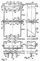
- FIGURES 7 and 8 are axial top and side views, respectively, of an electron gun according to the present invention.
- FIGURES 9, 10 and 11 are sectional views of the electron gun shown in Figure 7, taken along lines 9-9, 10-10 and 11-11, respectively.
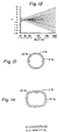
- FIGURE 12 shows the electron beam ray diagram for the beam forming region of the present electron gun.
- FIGURE 13 shows the electron beam current density contour from the beam forming region (first lens) of the present electron gun.
- FIGURE 14 shows the electron beam current density contour within the main lens produced by the second lens of the present electron gun, connected as shown in Figure 6.
- FIGURES 15a, 15b and 15c show the beam current density contour of the present electron gun, connected as shown in FIGURE 6, at the center of the screen, deflected to the upper right corner of the screen, and at the same deflected location on the screen but with a dynamic correction voltage applied to one electrode of the main (third) lens.
- FIGURE 16 is a schematic sectional view showing a second embodiment of a six grid electron gun, operating with the third and fifth grids at a second potential and the fourth and sixth grids at a third potential.
- FIGURE 17 shows the electron beam current density contour within the main lens produced by the second embodiment of the present electron gun, connected as shown in FIGURE 16.
- FIGURE 18 shows the electron beam current density contour at the center of the screen for the second embodiment of the present electron gun, connected as shown in FIGURE 16.
- an electron gun 40 is shown as comprising three equally spaced coplanar cathodes 42 (one for each beam), a control grid 44 (G1), a screen grid 46 (G2), a third electrode 48 (G3), a fourth electrode 50 (G4), a fifth electrode 52 (G5), the G5 electrode including a spatially separated portion G5′ identified as element 54, and a sixth electrode 56 (G6).
- the electrodes are spaced in the order named from the cathodes and are attached to a pair of support rods (not shown).
- the cathodes 42, the G1 electrode 44, the G2 electrode 46 and a portion of the G3 electrode 48 facing the G2 electrode 46 comprise a beam forming region of the electron gun 40.
- Another portion of the G3 electrode 48, the G4 electrode 50 and the G5 electrode 52 comprise a first asymmetric lens.
- the portion 54 of the G5′ electrode and the G6 electrode 56 comprise a main focusing (or second asymmetric) lens.
- Each cathode 42 comprises a cathode sleeve 58 closed at its forward end by a cap 60 having an end coating 62 of an electron emissive material thereon, as is known in the art.
- Each cathode 42 is indirectly heated by a heater coil (not shown) positioned within the sleeve 58.
- the G1 and G2 electrodes, 44 and 46 are two closely spaced substantially flat plates each having three pairs of inline apertures 64 and 66, respectively, therethrough.
- the apertures 64 and 66 are centered with the cathode coating 62, to initiate three equally-spaced coplanar electron beams 28 (as shown in Figure 1) directed towards the screen 22.
- the initial electron beam paths are substantially parallel, with the middle path coinciding with the central axis A-A of the electron gun.
- the G3 electrode 48 includes a substantially flat outer plate portion 68 having three inline apertures 70 therethrough, which are aligned with the apertures 66 and 64 in the G2 and G1 electrodes 46 and 44, respectively.
- the G3 electrode 48 also includes a pair of cup-shaped first and second portions 72 and 74, respectively, which are joined together at their open ends.
- the first portion 72 has three inline apertures 76 formed through the bottom of the cup, which are aligned with the apertures 70 in the plate 68.
- the second portion 74 of the G3 electrode has three apertures 78 formed through its bottom, which are aligned with the apertures 76 in the first portion 72. Extrusions 79 surround the apertures 78.
- the plate portions 68 with its inline apertures 70 may be formed as an integral part of the first portion 72.
- the G4 electrode 50 comprises a substantially flat plate having three inline apertures 80 formed therethrough, which are aligned with the apertures 78 in the G3 electrode.
- the G5 electrode 52 is a deep-drawn cup-shaped member having three apertures 82, surrounded by extrusions 83, formed in the bottom end thereof.
- the G5′ electrode 54 comprises a deep-drawn cup-shaped member having a recess 92, formed in the bottom end with three inline apertures 94 formed in the bottom surface thereof. Extrusions 95 surround the apertures 94.
- the opposite open end of the G5′ electrode 54 is closed by a second plate portion 96 having three openings 98 formed therethrough, which are aligned with and cooperate with the openings 90 in the first plate portion 88 in a manner described below.
- the G6 electrode 56 is a cup-shaped deep-drawn member having a large opening 100 at one end, through which all three electron beams pass, and an open end, which is attached to and closed by a plate member 102 that has three apertures 104 therethrough which are aligned with the apertures 94 in the G5′ electrode 54. Extrusions 105 surround the apertures 104.
- the shape of the recess 92 in the G5′ electrode 54 is shown in FIGURE 9.
- the recess 92 has a uniform vertical width at each of the electron beam paths, with rounded ends. Such a shape has been referred to as the "racetrack" shape.
- the shape of the large aperture 100 in the G6 electrode 56 is shown in FIGURE 10.
- the aperture 100 is vertically higher at the side electron beam paths than it is at the center beam path.
- Such a shape has been referred to as the "dogbone” or “barbell” shape.
- the first plate portion 88 of the G5 electrode 52 is spatially separated from, and faces the second plate portion 96 of the G5′ electrode 54.
- the apertures 90 in the first plate portion 88 of the G5 electrode 52 have extrusions, extending from the plate portion, that have been divided into two segments 106 and 108 for each aperture.
- the apertures 98 in the second plate portion 96 of the G5′ electrode 54 also have extrusions, extending from the plate portion 96, that have been divided into two segments 110 and 112 for each aperture. As shown in FIGURE 11, the segments 106 and 108 are interleaved with the segments 110 and 112.
- These segments are used to create quadrupole lenses in the paths of each electron beam when different potentials are applied to the G5 and G5′ electrodes 52 and 54, respectively.
- a dynamic voltage differential to either the G5 electrode 52 or the G5′ electrode 54, it is possible to use the quadrupole lenses established by the segments 106, 108, 110 and 112 to provide an astigmatic correction to the electron beams, to compensate for astigmatisms occurring in either the electron gun or in the deflection yoke.
- the electron gun is electrically connected as shown in FIGURE 6.
- the cathode operates at about 150V
- the G1 electrode is at ground potential
- the G2 and G4 electrodes are electrically interconnected and operate within the range of about 300V to 1000V
- the G3 and G5 electrodes also are electrically interconnected and operate at about 7kV
- the G6 electrode operates at an anode potential of about 25 kV.
- the first lens, L1 (FIGURE 6) provides a symmetrically-shaped high quality electron beam into the second lens, L2.
- the beam has a large divergence angle of about 120 milliradians and an electron distribution as shown by the ray diagram in FIGURE 12.
- the crossover for the electron beam, operating at about 4 mA, occurs at a distance of about 2.3mm (0.090 inch) from the cathode.
- the corresponding beam current density contour of one of the beams is shown in FIGURE 13. It can be seen that the present beam forming region does not introduce any appreciable asymmetry into the electron beam.
- the second lens, L2 comprising the G4 electrode 50 and the adjacent portions of the G3 electrode 48 and the G5 electrode 52, constitutes an asymmetric lens which provides a horizontally-elongated electron beam which, within the third or main focus lens, L3, has the beam spot contour shown in FIGURE 14.
- the substantially rectangular shape of the electron beam is produced by the rectangular apertures 80 formed through the G4 electrode 50. Since the Vertical dimensions of the apertures 80 are less than the horizontal dimensions, and the adjacent G3 and G5 electrodes operate at a potential greater than the potential on the G4 electrode, there is stronger vertical focusing of the beams prior to entering the main lens, L3.
- the G5′ electrode 54 is adapted to have a dynamic differential focus voltage applied thereto.
- That voltage ranges from the potential on the G5 electrode 52, with no deflection, to a voltage more positive than the voltage on the G5 electrode, but less positive than the voltage applied to the G4 electrode 50 and the G6 electrode 56, at maximum deflection.
- a slight misalignment of about 0.025 mm (0.001 inch) occurs in the apertures 64, 66 and 70 of the beam-forming region
- the main focus lens, L3, formed between the G5′ electrode 54 and the G6 electrode 56 also is a low aberration, asymmetric lens, which provides a vertically-elongated, or asymmetrically-shaped, electron beam spot at the center of the screen.
- the resultant beam spot, shown in FIGURE 15a has a substantially gaussian current density contour.
- deflection of the beam to the upper right corner of the screen causes substantial elongation of the central 50% region of the beam, with enlarged regions or halos of lower intensity surrounding the central region.
- the deflected electron beam current density contour can be improved as shown in FIGURE 15c.
- a second embodiment of the computer modeled electron gun 40 shown in FIGURES 7 and 8 is presented in TABLE II.
- the beam-forming region of the electron gun of the second embodiment is identical to the beam-forming region of the first embodiment, and like numbers are used to designate like tube elements throughout the electron gun.
- the electron gun 40 is electrically connected as shown in FIGURE 16.
- the cathode operates at about 150V
- the G1 electrode at ground potential
- the G2 electrode at about 400V.
- the G3 electrode is electrically interconnected to the G5 electrode and operates at about 7 kV
- the G4 electrode is electrically interconnected to the G6 electrode which operates at an anode potential of about 25 kV.
- the first lens, L1 (FIGURE 16) provides a symmetrically-shaped high quality electron beam into the second lens, L2. Since the beam-forming region of the second embodiment is identical to that of the first embodiment, FIGURES 12 and 13 also show, respectively, the electron distribution and beam current density contour for one of the electron beams therefrom.
- the second electron lens, L2 comprising the G4 electrode 50 and the adjacent portions of the G3 electrode 48 and the G5 electrode 52, constitutes an asymmetric lens which provides a horizontally-elongated, elliptically-shaped electron beam which, within the third or main focus lens, L3, has the beam current density contour shown in FIGURE 17.
- the elliptical shape of the beam is produced by the interaction of the rectangular apertures 80 in the G4 electrode 50 and voltage gradients in the second lens, L2.
- FIGURE 18 shows the resultant beam current density contour of an electron beam at the center of the screen.
- the horizontal dimension of the apertures 80 in the second embodiment is less than the vertical dimension, and the adjacent G3 and G5 electrodes operate at a potential less than the potential on the G4 electrode, weaker horizontal focusing of the beams occurs prior to entering the main lens, L3.
- FIGURES 15a and 18 are similar and demonstrate that acceptable performance can be achieved utilizing either embodiment.
- the electrical configuration shown in FIGURE 6 is preferred, because the anode potential is not introduced into the lower voltage region of the electron gun.
- a primary advantage of the embodiments presented in TABLES I and II over prior six-electrode electron guns, such as that described in U.S. Pat. 4,641,058, is that the initial asymmetric lens, L2, is located beyond the electron beam crossover point. Accordingly, the asymmetric effect of lens, L2, on the beam spot size and current density contour on the screen is relatively independent of the beam current. Additionally, the present structures provide beams of substantially constant current density, in both the horizontal and vertical directions, in the main lens.
- the embodiments described herein are exemplary of the invention and are not meant to be limiting.
- the rectangular apertures of the second embodiment of the G4 electrode 50 can be replaced with apertures of other suitable geometric shapes, to provide an asymmetric second lens.
- the focus voltage on the G3 and G5 electrodes can be selected to vary the strength of the electron lenses in the electron gun.
Landscapes
- Electrodes For Cathode-Ray Tubes (AREA)
- Video Image Reproduction Devices For Color Tv Systems (AREA)
Description
- The invention relates to a color cathode-ray tube having an electron gun with three electron lenses, and, more particularly, to a three-lens electron gun capable of providing asymmetrically-shaped electron beams of substantially constant current density.
- FIGURE 1 shows a conventional rectangular
color picture tube 10 having aglass envelope 11 comprising arectangular faceplate panel 12 and atubular neck 14 connected by arectangular funnel 16. Thepanel 12 comprises aviewing faceplate 18 and a peripheral flange orsidewall 20 which is sealed to thefunnel 16 by afrit seal 21. A mosaic three-color phosphor screen 22 is located on the inner surface of thefaceplate 18. The screen preferably is a line screen with the phosphor lines extending substantially perpendicular to the high frequency raster line scan of the tube (normal to the plane of the FIGURE 1). Alternatively, the screen could be a dot screen. A multi-apertured color selection electrode orshadow mask 24 is removably mounted, by conventional means, in predetermined spaced relation to thescreen 22. Aninline electron gun 26, shown schematically by dashed lines in FIGURE 1, is centrally mounted within theneck 14 to generate and direct threeelectron beams 28 along initially coplanar beam paths through themask 24 and toward thescreen 22. One type of electron gun that is conventional is a four grid bi-potential electron gun such as that shown in FIGURE 2 and described in U. S. Patent No. 4,620,133, issued to Morrell et al. on October 28, 1986. - The tube of FIGURE 1 is designed to be used with an external magnetic deflection yoke, such as
yoke 30 located in the region of the funnel-to-neck junction. When activated, theyoke 30 subjects the threebeams 28 to magnetic fields which cause the beams to scan horizontally and vertically in a rectangular raster over thescreen 22. The initial plane of deflection (at zero deflection) is shown by the line P-P in FIGURE 1 at about the middle of theyoke 30. Because of fringe fields, the zone of deflection of the tube extends axially from theyoke 30 into the region of thegun 26. For simplicity, the actual curvature of the deflected beam paths in the deflection zone is not shown in FIGURE 1. Theyoke 30 provides an inhomogeneous magnetic field that has a strong pincushion-like vertical deflection magnetic field and a strong barrel-like horizontal deflection magnetic field, to converge the electron beams at the peripheral part of thescreen 22. When the electron beams pass through such an inhomogeneous magnetic field, the beams are subject to distortions and defocusing. As a result, at the peripheral portions of thescreen 22, the shape of the electron beam spot is greatly distored. FIGURE 3 represents an electron beam spot for a single beam which is circular at the center of the screen and undergoes various types of distortions at the periphery of thescreen 22. As shown in FIGURE 3, the beam spot becomes horizontally elongated when deflected along the horizontal axis. The beam spot at the four corners of the screen comprises a combination of horizontally elongated portions and vertically elongated portion that form elliptically-shaped spots with halo-shaped elongations thereabout. The resolution is degraded as the electron beam is deflected, and the non-uniform focusing, which cannot be neglected, presents a problem which must be addressed. - The above-cited U.S. Patent 4,620,133 addresses the beam focus problem by providing an improved color imaging display system that includes a deflection yoke and an electron gun that has both an improved beam forming region, comprising a first grid, G1, a second grid, G2, a third grid, G3, and an improved main focusing lens, G3-G4, which works in conjunction with the deflection yoke and the beam forming region to provide an improved beam spot at the
screen 22. FIGURE 4a herein shows an electron beam current density contour, at the center of thescreen 22, for an electron beam produced by the beam forming region and the main lens of the electron gun shown in FIGURE 2. The beam current of the electron gun is 4 milliamperes. The electron beam current density contour of Fig. 4a comprises a relatively large center portion, having a substantially constant beam current of about 50% of the average beam current, and peripheral portions, where the beam current drops to about 5% of the average beam current and finally to about 1% of the average beam current. The beam is elliptically-shaped along the vertical axis to reduce the overfocusing action of the yoke when the beam is deflected. FIGURE 4b shows the beam current density contour within the main lens, L2, that is between the G3 and G4 electrodes of Fig. 2. The electron beam at this location is horizontally elongated; however, the 50% beam current density portion is contained within the small elliptical center section of the beam which is circumscribed by the larger elliptical portions which represent the 5% and 1% beam current density profiles. FIGURE 4c shows the electron beam current density contour of the electron beam deflected into the upper right hand corner of the screen. Some haloing occurs above and below the central portion of the beam. FIGURE 5 depicts the paths of the electrons emerging from the beam forming region of the electron gun of FIGURE 2 for various beam currents. In FIGURE 5a, the beam current is adjusted to 4 milliamperes, and a crossover point occurs at about 2.8 to 2.9 mm (110 to 115 mils) from the cathode located at the origin. At a distance of about 5.2 mm (200 mils) from the origin, the electrons are concentrated in the center portion of the beam. This distribution of electrons produces the current density contour, at the screen, shown in FIGURE 4a. The effect of the beam current on the location of the crossover point and on the beam current density contour is shown in Figures 5b and 5c. In FIGURE 5b, when the beam current is decreased to 0.8 millampere, the crossover point is shifted to a location about 1.14 mm (45 mils) from the cathode. It is apparent that the divergence angle of the electron beam is somewhat less at an operating current of 0.8 milliampere than at an operating current of 4.0 milliamperes (FIGURE 5a). In FIGURE 5c, at a beam current of 0.2 milliampere, the crossover point is located less than about 0.6 mm (25 mils) from the cathode, and the beam is virtually a laminar beam. - U.S. Patent 4,641,058, issued to Koshigoe et al. on Feb. 3, 1987, also discloses a four-grid bi-potential electron gun in which a prefocus astigmatic lens is formed between the second and third grids and a main astigmatic focus lens is formed between the third and fourth grids. The advantage of that two-lens structure over prior bi-potential structures is that, unlike various types of prior bi-potential electron guns, such as that shown in FIGURE 2, which provide an astigmatic shape to the electron beam by means of the first grid, Koshigoe et al. have utilized the second and/or third grids as the first astigmatic lens. The latter structure allegedly permits the astigmatic electron beam formed by the first astigmatic lens to be compensated for in the main astigmatic focus lens, to provide a substantially circular-shaped beam spot on a phosphor screen of a cathode ray tube. The structure described in the Koshigoe et al. patent is also applied to a composite lens type electron gun having six grids and three separate electron lenses, such as that shown in FIGURE 6. In the six grid structure of Koshigoe et al., the first (prefocus) lens, L1, is formed between the second and third grids; the third, fourth, and fifth grids constitute a sub-lens, L2; and the fifth and sixth grids constitute a main lens, L3. In this latter embodiment, the first (prefocus) lens serves as the first astigmatic lens, and the main lens serves as the second astigmatic lens. The allegation is that the deflected beam spot in this electron gun is superior to that obtained in prior art electron guns. However, in such an electron gun structure, the location of the crossover point is dependent upon the beam current of the electron gun. While the first asymmetric lens, L1, is formed in the region between the second and third grid electrodes, G2 and G3, respectively, the crossover point may occur either before or after lens L1, depending upon the electron beam current. At a high beam current of about 4 milliamperes (mA), the crossover point occurs after the lens L1, closer to the G3 electrode. Thus, the asymmetric effect of lens L1 is a function of beam current. It is therefore desirable to provide an electron lens which is insensitive to the beam current; i.e., the asymmetric lens should be located beyond the crossover point, regardless of the operating beam current of the electron gun. Additionally, it is desirable to have a gun structure which provides beams of substantially constant current density, in both the horizontal and vertical directions, in the main lens.
- The documents PATENT ABSTRACTS OF JAPAN, Vol. 3, No.141 (E 153) 21 November 1979, page 151 E.153; and JP-A-54120581, disclose an in-line electron gun for a colour cathode-ray tube for generating and directing three in-line electron beams along initially co-planar axes on paths towards a screen, including a plurality of spaced electrodes (15-20) which provide a first lens (15,16,17), a second lens (17,18,19) and a third lens (19,20) for focusing said electron beams, said first lens including a beam-forming region for providing beams to said second lens; said second lens being used as an Einzel lens for refracting electron beams, emerging off said axes from said first lens, towards said axes, and asymmetric beam-focusing means for providing beams to said third lens and said third lens for providing beams which agree in terms of shape to said screen.
- The above arrangement is intended primarily for providing beam spots with a circular cross-section, but the construction produced very high spherical aberration. Accordingly, a plate (18) is provided in the second lens with apertures for compensating for the spherical aberration.
- In Toshiba Review No.121, May-June 1979, S. Takenaka el al: "New Hi-Fi Focus Electron Gun for Color Cathode-Ray Tube", pages 30-35, there is an explanation of a focusing lens system for an electron gun including a beam shaping or pre-focus lens, a main lens and a sub-lens intermediate the pre-focus lens and the main lens for reducing the angular cross-section of the electron beam from the pre-focus lens.
- EP-A-104674 discloses a lens system for an electron gun comprising two lenses, namely a beam shaping lens (20,21,24) and main lens (25,26,37). In this arrangement an aperture insert (30) is inserted in the main lens to provide a correction for manufacturing tolerances in the basic lens system.
- US-A-2884559 discloses a lens system for an electron gun comprising two lenses, namely a beam shaping lens (13), and a main Einzel lens (25-28), wherein the inner two lens plates of the Einzel lens are provided with horizontal and vertical elliptically shaped apertures and are connected to receive the deflection voltages applied to the deflection plates in order to provide dynamic compensation to the shape of the beam spot.
- EP-A-0231964 discloses a lens system for an electron gun which has essentially two lenses, namely a beam shaping lens (20,24,27) and a main focusing lens (28,29). There is in addition inserted an auxiliary electrode (Gast) which is not a further lens, but which is connected to a dynamically varying voltage, which is in synchronism with the line deflection for providing a compensation or trimming effect to the shape of the electron beams.
- Patent Abstracts of Japan, Vol. 10, No 244 (E-430) [2300], 22 August 1986; & JP-A-61074246, disclose a three lens system for an electron gun wherein the centre lens, which may be regarded as an adaptation of the simple Einzel lens has an extra centre plate (9) with rectangular apertures for the three electron beams to provide compensation for defects in the shape of the beam; there is no asymmetric beam formation.
- The present invention provides in one aspect a colour cathode-ray tube, including an envelope having therein an inline electron gun for generating and directing three inline electron beams along initially coplanar axes on paths towards a screen on an interior portion of said envelope, said gun including a plurality of spaced electrodes which provide a first lens, a second lens and a third lens for focusing said electron beams, said first lens including a beam-forming region for providing substantially symmetrical beams to said second lens; said first lens comprising a first electrode, a second electrode and a first portion of a third electrode, said second lens comprising a second portion of said third electrode, a fourth electrode and a first portion of a fifth electrode, and said third lens comprising a second portion of said fifth electrode and a sixth electrode, said second electrode and said fourth electrode being interconnected, and said third electrode and said first portion of said fifth electrode being interconnected, said electrodes having suitable operating voltages applied thereto, said second lens including beam refraction means for refracting said electron beams, emerging off said axes from said first lens, toward said axes, and asymmetric beam-forming means comprising said fourth electrode for providing horizontally elongated asymmetrically-shaped beams to said third lens said fourth electrode including three horizontally elongated openings therein for producing said horizontally elongated, asymmetrically-shaped beams, and said third lens being a low-aberration main focusing lens for providing vertically elongated, asymmetrically-shaped beams of substantially constant current density to said screen, said asymmetric main focusing lens being formed by facing surfaces of the second portion of said fifth electrode and said sixth electrode each of which includes a recess formed at the respective outer edge extending to said second portion of said fifth electrode and said sixth electrode, respectively, each recess having a greater horizontal than vertical dimension, and three set-back apertures in the bottom of the respective recess, each single aperture being surrounded by a single extrusion.
- In another aspect, the invention provides a colour cathode-ray tube, including an envelope having therein an inline electron gun for generating and directing three inline electron beams along initially coplanar axes on paths toward a screen on an interior portion of said envelope, said gun including a plurality of spaced electrodes which provide a first lens, a second lens and a third lens for focusing said electron beams, said first lens including a beam-forming region for providing substantially symmetrical beams to said second lens; said first lens comprising a first electrode, a second electrode and a first portion of a third electrode, said second lens comprising a second portion of said third electrode, a fourth electrode and a first portion of a fifth electrode, and said third lens comprising a second portion of said fifth electrode and a sixth electrode, said third electrode and said first portion of said fifth electrode being interconnected, and said fourth electrode and said sixth electrode being interconnected, said electrodes having suitable operating voltages applied thereto, said second lens including beam refraction means for refracting said electron beams emerging off said axes from said first lens, toward said axes, and asymmetric beam-forming means comprising said fourth electrode for providing horizontally elongated, asymmetrically-shaped beams to said third lens, said fourth electrode including three vertically elongated openings therein for producing said horizontally elongated, asymmetrically-shaped beams, and said third lens being a low-aberration main focusing lens for providing vertically elongated, asymmetrically-shaped beams of substantially constant density to said screen, said asymmetric main focusing lens being formed by facing surfaces of the second portion of said fifth electrode and said sixth electrode each of which includes a recess formed at the respective outer edge extending to said second portion of said fifth electrode and said sixth electrode, respectively, each recess having a greater horizontal than vertical dimension, and three set-back aperture in the bottom of the respective recess, each single aperture being surrounded by a single extrusion.
- The present invention as claimed provides an improvement in color picture tubes which include an electron gun for generating and directing three electron beams, a centre beam and two side beams, along initially coplanar paths towards the screen of the tube. The gun includes a plurality of spaced electrodes which provide a first lens including a beam forming region for providing substantially symmetrical beams to a second lens. The second lens includes beam refraction means for refracting the electron beams, emerging off the axis from the first lens, toward the axis, and asymmetric beam-focusing means for providing asymmetrically shaped beams to a third lens. The third lens is a low aberration main focusing lens for providing an asymmetrically shaped beam of substantially constant current density to the screen.
- In the drawings:
- FIGURE 1 is a plan view, partially in axially section, of a conventional color cathode-ray tube.
- FIGURE 2 is a schematic sectional view showing an overall construction of a conventional bi-potential four-grid electron gun.
- FIGURE 3 is a representation showing the shapes of electron beam spots on the screen of a conventional color cathode-ray tube.
- FIGURE 4a shows the electron beam current density contour at the center of the screen, for the conventional electron gun of FIGURE 2; FIGURE 4b shows the electron beam current density contour within the main lens; and FIGURE 4c shows the current density contour for the electron beam deflected to the upper right hand corner of FIGURE 3.
- FIGURE 5a shows the electron beam ray diagram for the beam forming region of the conventional electron gun of FIGURE 2, operating at a beam current of 4.0 milliamperes; FIGURE 5b shows that same conventional electron gun operating at a beam current of 0.8 milliampere; and FIGURE 5c shows that same conventional electron gun operating at a beam current of 0.2 milliampere.
- FIGURE 6 is a schematic sectional view showing a six grid electron gun operating with the second and fourth grids at a first potential and the third and fifth grids at a second potential.
- FIGURES 7 and 8 are axial top and side views, respectively, of an electron gun according to the present invention.
- FIGURES 9, 10 and 11 are sectional views of the electron gun shown in Figure 7, taken along lines 9-9, 10-10 and 11-11, respectively.
- FIGURE 12 shows the electron beam ray diagram for the beam forming region of the present electron gun.
- FIGURE 13 shows the electron beam current density contour from the beam forming region (first lens) of the present electron gun.
- FIGURE 14 shows the electron beam current density contour within the main lens produced by the second lens of the present electron gun, connected as shown in Figure 6.
- FIGURES 15a, 15b and 15c show the beam current density contour of the present electron gun, connected as shown in FIGURE 6, at the center of the screen, deflected to the upper right corner of the screen, and at the same deflected location on the screen but with a dynamic correction voltage applied to one electrode of the main (third) lens.
- FIGURE 16 is a schematic sectional view showing a second embodiment of a six grid electron gun, operating with the third and fifth grids at a second potential and the fourth and sixth grids at a third potential.
- FIGURE 17 shows the electron beam current density contour within the main lens produced by the second embodiment of the present electron gun, connected as shown in FIGURE 16.
- FIGURE 18 shows the electron beam current density contour at the center of the screen for the second embodiment of the present electron gun, connected as shown in FIGURE 16.
- Referring to FIGURES 7 and 8, an
electron gun 40 according to the present invention is shown as comprising three equally spaced coplanar cathodes 42 (one for each beam), a control grid 44 (G1), a screen grid 46 (G2), a third electrode 48 (G3), a fourth electrode 50 (G4), a fifth electrode 52 (G5), the G5 electrode including a spatially separated portion G5′ identified aselement 54, and a sixth electrode 56 (G6). The electrodes are spaced in the order named from the cathodes and are attached to a pair of support rods (not shown). - The
cathodes 42, theG1 electrode 44, theG2 electrode 46 and a portion of theG3 electrode 48 facing theG2 electrode 46 comprise a beam forming region of theelectron gun 40. Another portion of theG3 electrode 48, theG4 electrode 50 and theG5 electrode 52 comprise a first asymmetric lens. Theportion 54 of the G5′ electrode and theG6 electrode 56 comprise a main focusing (or second asymmetric) lens. - Each
cathode 42 comprises acathode sleeve 58 closed at its forward end by acap 60 having anend coating 62 of an electron emissive material thereon, as is known in the art. Eachcathode 42 is indirectly heated by a heater coil (not shown) positioned within thesleeve 58. - The G1 and G2 electrodes, 44 and 46, are two closely spaced substantially flat plates each having three pairs of
inline apertures apertures cathode coating 62, to initiate three equally-spaced coplanar electron beams 28 (as shown in Figure 1) directed towards thescreen 22. Preferably, the initial electron beam paths are substantially parallel, with the middle path coinciding with the central axis A-A of the electron gun. - The
G3 electrode 48 includes a substantially flatouter plate portion 68 having threeinline apertures 70 therethrough, which are aligned with theapertures G1 electrodes G3 electrode 48 also includes a pair of cup-shaped first andsecond portions first portion 72 has threeinline apertures 76 formed through the bottom of the cup, which are aligned with theapertures 70 in theplate 68. Thesecond portion 74 of the G3 electrode has threeapertures 78 formed through its bottom, which are aligned with theapertures 76 in thefirst portion 72. Extrusions 79 surround theapertures 78. Alternatively, theplate portions 68 with itsinline apertures 70 may be formed as an integral part of thefirst portion 72. - The
G4 electrode 50 comprises a substantially flat plate having threeinline apertures 80 formed therethrough, which are aligned with theapertures 78 in the G3 electrode. - The
G5 electrode 52 is a deep-drawn cup-shaped member having threeapertures 82, surrounded by extrusions 83, formed in the bottom end thereof. A substantiallyflat plate member 84 having threeapertures 86, aligned with theapertures 82, is attached to and closes the open end of theG5 electrode 52. Afirst plate portion 88, having a plurality ofopenings 90 therein, is attached to the opposite surface of theplate member 84. - The G5′
electrode 54 comprises a deep-drawn cup-shaped member having arecess 92, formed in the bottom end with threeinline apertures 94 formed in the bottom surface thereof. Extrusions 95 surround theapertures 94. The opposite open end of the G5′electrode 54 is closed by asecond plate portion 96 having threeopenings 98 formed therethrough, which are aligned with and cooperate with theopenings 90 in thefirst plate portion 88 in a manner described below. - The
G6 electrode 56 is a cup-shaped deep-drawn member having alarge opening 100 at one end, through which all three electron beams pass, and an open end, which is attached to and closed by aplate member 102 that has threeapertures 104 therethrough which are aligned with theapertures 94 in the G5′electrode 54.Extrusions 105 surround theapertures 104. - The shape of the
recess 92 in the G5′electrode 54 is shown in FIGURE 9. Therecess 92 has a uniform vertical width at each of the electron beam paths, with rounded ends. Such a shape has been referred to as the "racetrack" shape. - The shape of the
large aperture 100 in theG6 electrode 56 is shown in FIGURE 10. Theaperture 100 is vertically higher at the side electron beam paths than it is at the center beam path. Such a shape has been referred to as the "dogbone" or "barbell" shape. - The
first plate portion 88 of theG5 electrode 52 is spatially separated from, and faces thesecond plate portion 96 of the G5′electrode 54. Theapertures 90 in thefirst plate portion 88 of theG5 electrode 52 have extrusions, extending from the plate portion, that have been divided into twosegments apertures 98 in thesecond plate portion 96 of the G5′electrode 54 also have extrusions, extending from theplate portion 96, that have been divided into twosegments segments segments electrodes G5 electrode 52 or the G5′electrode 54, it is possible to use the quadrupole lenses established by thesegments - Specific dimensions of a computer-modeled electron gun for a first preferred embodiment are presented in TABLE I.


- In the embodiment presented in TABLE I, the electron gun is electrically connected as shown in FIGURE 6. Typically, the cathode operates at about 150V, the G1 electrode is at ground potential, the G2 and G4 electrodes are electrically interconnected and operate within the range of about 300V to 1000V, the G3 and G5 electrodes also are electrically interconnected and operate at about 7kV, and the G6 electrode operates at an anode potential of about 25 kV.
- While the electrical parameters of the preferred embodiment are similar to those described in U.S. Patent No. 4,641,058, cited above, the structural differences in the present electron gun provide superior performance.
- In the
present electron gun 40, the first lens, L1, (FIGURE 6) provides a symmetrically-shaped high quality electron beam into the second lens, L2. The beam has a large divergence angle of about 120 milliradians and an electron distribution as shown by the ray diagram in FIGURE 12. The crossover for the electron beam, operating at about 4 mA, occurs at a distance of about 2.3mm (0.090 inch) from the cathode. The corresponding beam current density contour of one of the beams is shown in FIGURE 13. It can be seen that the present beam forming region does not introduce any appreciable asymmetry into the electron beam. - In the
present electron gun 40,the second lens, L2, comprising theG4 electrode 50 and the adjacent portions of theG3 electrode 48 and theG5 electrode 52, constitutes an asymmetric lens which provides a horizontally-elongated electron beam which, within the third or main focus lens, L3, has the beam spot contour shown in FIGURE 14. The substantially rectangular shape of the electron beam is produced by therectangular apertures 80 formed through theG4 electrode 50. Since the Vertical dimensions of theapertures 80 are less than the horizontal dimensions, and the adjacent G3 and G5 electrodes operate at a potential greater than the potential on the G4 electrode, there is stronger vertical focusing of the beams prior to entering the main lens, L3. The G5′electrode 54 is adapted to have a dynamic differential focus voltage applied thereto. That voltage ranges from the potential on theG5 electrode 52, with no deflection, to a voltage more positive than the voltage on the G5 electrode, but less positive than the voltage applied to theG4 electrode 50 and theG6 electrode 56, at maximum deflection. In the event that a slight misalignment of about 0.025 mm (0.001 inch) occurs in theapertures - The main focus lens, L3, formed between the G5′
electrode 54 and theG6 electrode 56 also is a low aberration, asymmetric lens, which provides a vertically-elongated, or asymmetrically-shaped, electron beam spot at the center of the screen. The resultant beam spot, shown in FIGURE 15a, has a substantially gaussian current density contour. As shown in FIGURE 15b, deflection of the beam to the upper right corner of the screen causes substantial elongation of the central 50% region of the beam, with enlarged regions or halos of lower intensity surrounding the central region. - By applying to the G5′ electrode 54 a dynamic differential focus voltage that ranges from the potential on G5, with no deflection, to about 1000 volts more positive than the voltage applied to the
G5 electrode 52, at maximum deflection, the deflected electron beam current density contour can be improved as shown in FIGURE 15c. - A second embodiment of the computer modeled
electron gun 40 shown in FIGURES 7 and 8 is presented in TABLE II. The beam-forming region of the electron gun of the second embodiment is identical to the beam-forming region of the first embodiment, and like numbers are used to designate like tube elements throughout the electron gun.

- In the embodiment presented in TABLE II, the
electron gun 40 is electrically connected as shown in FIGURE 16. Typically, the cathode operates at about 150V, the G1 electrode at ground potential, and the G2 electrode at about 400V. The G3 electrode is electrically interconnected to the G5 electrode and operates at about 7 kV, and the G4 electrode is electrically interconnected to the G6 electrode which operates at an anode potential of about 25 kV. - In the present electron gun, the first lens, L1, (FIGURE 16) provides a symmetrically-shaped high quality electron beam into the second lens, L2. Since the beam-forming region of the second embodiment is identical to that of the first embodiment, FIGURES 12 and 13 also show, respectively, the electron distribution and beam current density contour for one of the electron beams therefrom.
- In the second embodiment, the second electron lens, L2, comprising the
G4 electrode 50 and the adjacent portions of theG3 electrode 48 and theG5 electrode 52, constitutes an asymmetric lens which provides a horizontally-elongated, elliptically-shaped electron beam which, within the third or main focus lens, L3, has the beam current density contour shown in FIGURE 17. The elliptical shape of the beam is produced by the interaction of therectangular apertures 80 in theG4 electrode 50 and voltage gradients in the second lens, L2. FIGURE 18 shows the resultant beam current density contour of an electron beam at the center of the screen. Since the horizontal dimension of theapertures 80 in the second embodiment is less than the vertical dimension, and the adjacent G3 and G5 electrodes operate at a potential less than the potential on the G4 electrode, weaker horizontal focusing of the beams occurs prior to entering the main lens, L3. - Despite the differences in structure and operating voltages between the first and second embodiments of the
electron gun 40 presented in TABLES I and II, the beam contours shown in FIGURES 15a and 18 are similar and demonstrate that acceptable performance can be achieved utilizing either embodiment. The electrical configuration shown in FIGURE 6 is preferred, because the anode potential is not introduced into the lower voltage region of the electron gun. - A primary advantage of the embodiments presented in TABLES I and II over prior six-electrode electron guns, such as that described in U.S. Pat. 4,641,058, is that the initial asymmetric lens, L2, is located beyond the electron beam crossover point. Accordingly, the asymmetric effect of lens, L2, on the beam spot size and current density contour on the screen is relatively independent of the beam current. Additionally, the present structures provide beams of substantially constant current density, in both the horizontal and vertical directions, in the main lens.
- The embodiments described herein are exemplary of the invention and are not meant to be limiting. For example, the rectangular apertures of the second embodiment of the
G4 electrode 50 can be replaced with apertures of other suitable geometric shapes, to provide an asymmetric second lens. Additionally, the focus voltage on the G3 and G5 electrodes can be selected to vary the strength of the electron lenses in the electron gun.
Claims (8)
- A color cathode-ray tube, including an envelope having therein an inline electron gun for generating and directing three inline electron beams along initially coplanar axes on paths towards a screen on an interior portion of said envelope, said gun including a plurality of spaced electrodes which provide a first lens, a second lens and a third lens for focusing said electron beams, said first lens including a beam-forming region for providing substantially symmetrical beams to said second lens;
said first lens (L1) comprising a first electrode (44), a second electrode (46) and a first portion of a third electrode (48), said second lens (L2) comprising a second portion of said third electrode, a fourth electrode (50) and a first portion (52) of a fifth electrode, and said third lens (L3) comprising a second portion (54) of said fifth electrode and a sixth electrode (56), said second electrode (46) and said fourth electrode (50) being interconnected, and said third electrode (48) and said first portion (52) of said fifth electrode being interconnected, said electrodes having suitable operating voltages applied thereto,
said second lens (L2) including beam refraction means (48-52) for refracting said electron beams (28), emerging off said axes from said first lens (L1), toward said axes, and asymmetric beam-forming means comprising said fourth electrode (50) for providing horizontally elongated, asymmetrically-shaped beams to said third lens (L3), said fourth electrode including three horizontally elongated openings (80) therein for producing said horizontally elongated, asymmetrically-shaped beams, and
said third lens (L3) being a low-aberration main focusing lens for providing vertically elongated, asymmetrically-shaped beams of substantially constant current density to said screen (22), said asymmetric main focusing lens being formed by facing surfaces of the second portion (54) of said fifth electrode and said sixth electrode (56) each of which includes a recess (92, 100) formed at the respective outer edge extending to said second portion (54) of said fifth electrode and said sixth electrode (56), respectively, each recess having a greater horizontal than vertical dimension, and three set-back apertures (94,104) in the bottom of the respective recess (92,100), each single aperture (94,104) being surrounded by a single extrusion (95, 105). - The tube as described in claim 1, characterized in that said second electrode (46) and said fourth electrode (50) is adapted to operate at a first potential, said third electrode (48) and said first portion (52) of said fifth electrode is adapted to operate at a second potential which is more positive than said first potential, and said sixth electrode (56) is adapted to operate at a third potential which is more positive than said first and said second potentials.
- The tube as described in claim 2, characterized in that said second portion (54) of said fifth electrode is spatially separated from said first portion (52) of said fifth electrode and is adapted to have a dynamic potential applied thereto, said dynamic potential ranging from said second potential to a fourth potential greater than said potential but substantially less than said third potential.
- A color cathode-ray tube, including an envelope having therein an inline electron gun for generating and directing three inline electron beams along initially coplanar axes on paths towards a screen on an interior portion of said envelope, said gun including a plurality of spaced electrodes which provide a first lens, a second lens and a third lens for focusing said electron beams, said first lens including a beam-forming region for providing substantially symmetrical beams to said second lens;
said first lens (L1) comprising a first electrode (44), a second electrode (46) and a first portion of a third electrode (48), said second lens (L2) comprising a second portion of said third electrode, a fourth electrode (50) and a first portion (52) of a fifth electrode, and said third lens (L3) comprising a second portion (54) of said fifth electrode and a sixth electrode (56), said third electrode (48) and said first portion (52) of said fifth electrode being interconnected, and said fourth electrode (50) and said sixth electrode (56) being interconnected, said electrodes having suitable operating voltages applied thereto,
said second lens (L2) including beam refraction means (48-52) for refracting said electron beams (28), emerging off said axes from said first lens (L1), toward said axes, and asymmetric beam-forming means comprising said fourth electrode (50) for providing horizontally elongated, asymmetrically-shaped beams to said third lens (L3), said fourth electrode including three vertically elongated openings (80) therein for producing said horizontally elongated, asymmetrically-shaped beams, and
said third lens (L3) being a low-aberration main focusing lens for providing vertically elongated, asymmetrically-shaped beams of substantially constant density to said screen (22), said asymmetric main focusing lens being formed by facing surfaces of the second portion (54) of said fifth electrode and said sixth electrode (56) each of which includes a recess (92, 100) formed at the respective outer edge extending to said second portion (54) of said fifth electrode and said sixth electrode (56), respectively, each recess having a greater horizontal than vertical dimension, and three set-back apertures (94,104) in the bottom of the respective recess (92,100), each single aperture (94,104) being surrounded by a single extrusion (95,105). - The tube as described in claim 4, characterized in that said second electrode (46) is adapted to operate at a first potential, said third electrode and said first portion (52) of said fifth electrode are adapted to operate at a second potential which is more positive than said first potential, and said fourth electrode (50) and said sixth (56) are adapted to operate at a third potential which is more positive than said first and second potentials.
- The tube as described in claim 5, characterized in that said second portion (54) of said fifth electrode is spatially separated from said first portion (52) of said fifth electrode and is adapted to have a dynamic potential applied thereto, said dynamic potential ranging from said second potential to a fourth potential, which is more positive than said second potential but less positive than said third potential.
- A color cathode-ray tube, including an envelope having therein an inline electron gun for generating and directing three inline electron beams along initially coplanar axes on paths towards a screen on an interior portion of said envelope, said gun including a plurality of spaced electrodes which provide a first lens, a second lens and a third lens for focusing said electron beams, said first lens including a beam-forming region for providing substantially symmetrical beams to said second lens;
said first lens (L1) comprising a first electrode (44), a second electrode (46) and a first portion of a third electrode (48), said second lens (L2) comprising a second portion of said third electrode, a fourth electrode (50) and a first portion (52) of a fifth electrode, and said third lens (L3) comprising a second portion (54) of said fifth electrode and a sixth electrode (56), said second electrode (46) and said fourth electrode (50) being interconnected, and said third electrode (48) and said first portion (52) of said fifth electrode being interconnected, whereby in use suitable operating voltages are applied to said electrodes,
said second lens (L2) including beam refraction means (48-52) for refracting said electron beams (28), emerging off said axes from said first lens (L1), toward said axes, and asymmetric beam-forming means comprising said fourth electrode (50) for providing horizontally elongated, asymmetrically-shaped beams to said third lens (L3), said fourth electrode including three horizontally elongated openings (80) therein for producing said horizontally elongated, asymmetrically-shaped beams, and
said third lens (L3) being a low-aberration main focusing lens for providing vertically elongated, asymmetrically-shaped beams of substantially constant current density to said screen (22), said asymmetric main focusing lens being formed by facing surfaces of the second portion (54) of said fifth electrode and said sixth electrode (56) each of which includes a recess (92,100) formed at the respective outer edge extending to said second portion (54) of said fifth electrode and said sixth electrode (56), respectively, each recess having a greater horizontal than vertical dimension, and three set-back apertures (94,104) in the bottom of the respective recess (92,100), each single aperture (94,104) being surrounded by a single extrusion (95,105). - A color cathode-ray tube, including an envelope having therein an inline electron gun for generating and directing three inline electron beams along initially coplanar axes on paths towards a screen on an interior portion of said envelope, said gun including a plurality of spaced electrodes which provide a first lens, a second and a third lens for focusing said electron beams, said first lens including a beam-forming region for providing substantially symmetrical beams to said second lens;
said first lens (L1) comprising a first electrode (44), a second electrode (46) and a first portion of a third electrode (48), said second lens (L2) comprising a second portion of said third electrode, a fourth electrode (50) and a first portion (52) of a fifth electrode, and said third lens (L3) comprising a second portion (54) of said fifth electrode and a sixth electrode (56), said third electrode (48) and said first portion (52) of said fifth electrode being interconnected, and said fourth electrode (50) and said sixth electrode (56) being interconnected, whereby in use suitable operating voltages are applied to said electrodes,
said second lens (L2) including beam refraction means (48-52) for refracting said electron beams (28), emerging off said axes from said first lens (L1), toward said axes, and asymmetric beam-forming means comprising said fourth electrode (50) for providing horizontally elongated, asymmetrically-shaped beams to said third lens (L3), said fourth electrode including three vertically elongated openings (80) therein for producing said horizontally elongated, asymmetrically-shaped beams, and
said third lens (L3) being a low-aberration main focusing lens for providing vertically elongated, asymmetrically-shaped beams of substantially constant density to said screen (22), said asymmetric main focusing lens being formed by facing surfaces of the second portion (54) of said fifth electrode and said sixth electrode (56) each of which includes a recess (92,100) formed at the respective outer edge extending to said second portion (54) of said fifth electrode and said sixth electrode (56), respectively, each recess having a greater horizontal then vertical dimension, and three set-back apertures (94,104) in the bottom of the respective recess (92,100), each single aperture (94,104) being surrounded by a single extrusion (95,105).
Applications Claiming Priority (6)
| Application Number | Priority Date | Filing Date | Title |
|---|---|---|---|
| GB878700793A GB8700793D0 (en) | 1987-01-14 | 1987-01-14 | Db-xl gun design |
| GB878700792A GB8700792D0 (en) | 1987-01-14 | 1987-01-14 | Qpf-xl gun design |
| GB8700793 | 1987-01-14 | ||
| GB8700792 | 1987-01-14 | ||
| US07/128,951 US4764704A (en) | 1987-01-14 | 1987-12-04 | Color cathode-ray tube having a three-lens electron gun |
| US128951 | 1987-12-04 |
Publications (3)
| Publication Number | Publication Date |
|---|---|
| EP0275191A2 EP0275191A2 (en) | 1988-07-20 |
| EP0275191A3 EP0275191A3 (en) | 1989-06-07 |
| EP0275191B1 true EP0275191B1 (en) | 1995-09-27 |
Family
ID=27263286
Family Applications (1)
| Application Number | Title | Priority Date | Filing Date |
|---|---|---|---|
| EP88300247A Expired - Lifetime EP0275191B1 (en) | 1987-01-14 | 1988-01-13 | Color cathode-ray tube having a three-lens electron gun |
Country Status (3)
| Country | Link |
|---|---|
| EP (1) | EP0275191B1 (en) |
| JP (1) | JPH0748354B2 (en) |
| DE (1) | DE3854506T2 (en) |
Families Citing this family (4)
| Publication number | Priority date | Publication date | Assignee | Title |
|---|---|---|---|---|
| US4877998A (en) * | 1988-10-27 | 1989-10-31 | Rca Licensing Corp. | Color display system having an electron gun with dual electrode modulation |
| CA2039501C (en) * | 1990-04-16 | 1999-02-02 | Loren Lee Maninger | Color picture tube having inline electron gun with focus adjustement means |
| JP3576217B2 (en) * | 1993-09-30 | 2004-10-13 | 株式会社東芝 | Picture tube device |
| KR100386182B1 (en) * | 1994-10-24 | 2004-02-25 | 소니 가부시끼 가이샤 | Electron gun of cathode ray tube and manufacturing method of cathode ray tube |
Citations (2)
| Publication number | Priority date | Publication date | Assignee | Title |
|---|---|---|---|---|
| US4620133A (en) * | 1982-01-29 | 1986-10-28 | Rca Corporation | Color image display systems |
| EP0231964A1 (en) * | 1986-01-21 | 1987-08-12 | Koninklijke Philips Electronics N.V. | Colour display tube with reduced deflection defocussing |
Family Cites Families (3)
| Publication number | Priority date | Publication date | Assignee | Title |
|---|---|---|---|---|
| NL219031A (en) * | 1956-09-07 | |||
| NL8203322A (en) * | 1982-08-25 | 1984-03-16 | Philips Nv | COLOR IMAGE TUBE. |
| JPS63158732A (en) * | 1986-12-22 | 1988-07-01 | Toshiba Corp | Color cathode-ray tube device |
-
1988
- 1988-01-13 DE DE3854506T patent/DE3854506T2/en not_active Expired - Fee Related
- 1988-01-13 JP JP63006696A patent/JPH0748354B2/en not_active Expired - Fee Related
- 1988-01-13 EP EP88300247A patent/EP0275191B1/en not_active Expired - Lifetime
Patent Citations (2)
| Publication number | Priority date | Publication date | Assignee | Title |
|---|---|---|---|---|
| US4620133A (en) * | 1982-01-29 | 1986-10-28 | Rca Corporation | Color image display systems |
| EP0231964A1 (en) * | 1986-01-21 | 1987-08-12 | Koninklijke Philips Electronics N.V. | Colour display tube with reduced deflection defocussing |
Non-Patent Citations (2)
| Title |
|---|
| PATENT ABSTRACTS OF JAPAN, vol. 10, no. 244 (E-430)(2300), 22nd August 1986 & JP-A-6 174 246 * |
| TOSHIBA REVIEW, no. 121, May - Jun 1979, S. TAKENAKA et al.: "New Hi-Fi Focus Electron Gun for Color Cathode-Ray Tube", pages 30 - 35 * |
Also Published As
| Publication number | Publication date |
|---|---|
| EP0275191A2 (en) | 1988-07-20 |
| JPH0748354B2 (en) | 1995-05-24 |
| JPS63198241A (en) | 1988-08-16 |
| DE3854506D1 (en) | 1995-11-02 |
| EP0275191A3 (en) | 1989-06-07 |
| DE3854506T2 (en) | 1996-04-04 |
Similar Documents
| Publication | Publication Date | Title |
|---|---|---|
| US4877998A (en) | Color display system having an electron gun with dual electrode modulation | |
| US4764704A (en) | Color cathode-ray tube having a three-lens electron gun | |
| US4388552A (en) | Color picture tube having an improved expanded focus lens type inline electron gun | |
| EP0986088B1 (en) | Color cathode ray tube having a low dynamic focus voltage | |
| US5066887A (en) | Color picture tube having an inline electron gun with an astigmatic prefocusing lens | |
| EP0235975B1 (en) | Crt and color display system | |
| US4520292A (en) | Cathode-ray tube having an asymmetric slot formed in a screen grid electrode of an inline electron gun | |
| EP0300704B1 (en) | Color picture tube having an inline electron gun with an einzel lens | |
| US4558253A (en) | Color picture tube having an inline electron gun with asymmetric focusing lens | |
| EP0300705B1 (en) | Color picture tube having an inline electron gun with an einzel lens | |
| US5430349A (en) | Color picture tube having an inline electron gun with three astigmatic lenses | |
| CA1237464A (en) | Electron gun having a two piece screen grid electrode means | |
| EP0452789B1 (en) | Color picture tube having inline electron gun with focus adjustment means | |
| EP0275191A2 (en) | Color cathode-ray tube having a three-lens electron gun | |
| US4590403A (en) | Color picture tube having an improved inline electron gun | |
| KR970006037B1 (en) | Cathode ray tube with improved electron gun | |
| JP3672390B2 (en) | Electron gun for color cathode ray tube | |
| GB2144903A (en) | Cathode-ray tube with electron gun having an astigmatic beam forming region | |
| RU2040065C1 (en) | Color cathode-ray tube | |
| GB2097577A (en) | Electron gun with improved beam forming region and cathode-ray tube and television receiver including same |
Legal Events
| Date | Code | Title | Description |
|---|---|---|---|
| PUAI | Public reference made under article 153(3) epc to a published international application that has entered the european phase |
Free format text: ORIGINAL CODE: 0009012 |
|
| AK | Designated contracting states |
Kind code of ref document: A2 Designated state(s): DE FR GB IT |
|
| RAP1 | Party data changed (applicant data changed or rights of an application transferred) |
Owner name: RCA LICENSING CORPORATION |
|
| PUAL | Search report despatched |
Free format text: ORIGINAL CODE: 0009013 |
|
| AK | Designated contracting states |
Kind code of ref document: A3 Designated state(s): DE FR GB IT |
|
| 16A | New documents despatched to applicant after publication of the search report | ||
| 17P | Request for examination filed |
Effective date: 19891106 |
|
| 17Q | First examination report despatched |
Effective date: 19911023 |
|
| RAP1 | Party data changed (applicant data changed or rights of an application transferred) |
Owner name: RCA THOMSON LICENSING CORPORATION |
|
| GRAA | (expected) grant |
Free format text: ORIGINAL CODE: 0009210 |
|
| AK | Designated contracting states |
Kind code of ref document: B1 Designated state(s): DE FR GB IT |
|
| ET | Fr: translation filed | ||
| REF | Corresponds to: |
Ref document number: 3854506 Country of ref document: DE Date of ref document: 19951102 |
|
| ITF | It: translation for a ep patent filed | ||
| PLBE | No opposition filed within time limit |
Free format text: ORIGINAL CODE: 0009261 |
|
| STAA | Information on the status of an ep patent application or granted ep patent |
Free format text: STATUS: NO OPPOSITION FILED WITHIN TIME LIMIT |
|
| 26N | No opposition filed | ||
| REG | Reference to a national code |
Ref country code: GB Ref legal event code: IF02 |
|
| REG | Reference to a national code |
Ref country code: FR Ref legal event code: D6 |
|
| REG | Reference to a national code |
Ref country code: GB Ref legal event code: 746 Effective date: 20030110 |
|
| PGFP | Annual fee paid to national office [announced via postgrant information from national office to epo] |
Ref country code: GB Payment date: 20051123 Year of fee payment: 19 |
|
| PGFP | Annual fee paid to national office [announced via postgrant information from national office to epo] |
Ref country code: DE Payment date: 20060123 Year of fee payment: 19 |
|
| PGFP | Annual fee paid to national office [announced via postgrant information from national office to epo] |
Ref country code: FR Payment date: 20060130 Year of fee payment: 19 |
|
| PGFP | Annual fee paid to national office [announced via postgrant information from national office to epo] |
Ref country code: IT Payment date: 20060131 Year of fee payment: 19 |
|
| PG25 | Lapsed in a contracting state [announced via postgrant information from national office to epo] |
Ref country code: DE Free format text: LAPSE BECAUSE OF NON-PAYMENT OF DUE FEES Effective date: 20070801 |
|
| GBPC | Gb: european patent ceased through non-payment of renewal fee |
Effective date: 20070113 |
|
| REG | Reference to a national code |
Ref country code: FR Ref legal event code: ST Effective date: 20070930 |
|
| PG25 | Lapsed in a contracting state [announced via postgrant information from national office to epo] |
Ref country code: GB Free format text: LAPSE BECAUSE OF NON-PAYMENT OF DUE FEES Effective date: 20070113 |
|
| PG25 | Lapsed in a contracting state [announced via postgrant information from national office to epo] |
Ref country code: FR Free format text: LAPSE BECAUSE OF NON-PAYMENT OF DUE FEES Effective date: 20070131 |
|
| PG25 | Lapsed in a contracting state [announced via postgrant information from national office to epo] |
Ref country code: IT Free format text: LAPSE BECAUSE OF NON-PAYMENT OF DUE FEES Effective date: 20070113 |