EP0274794A2 - Device to be placed in the uterus - Google Patents
Device to be placed in the uterus Download PDFInfo
- Publication number
- EP0274794A2 EP0274794A2 EP87202529A EP87202529A EP0274794A2 EP 0274794 A2 EP0274794 A2 EP 0274794A2 EP 87202529 A EP87202529 A EP 87202529A EP 87202529 A EP87202529 A EP 87202529A EP 0274794 A2 EP0274794 A2 EP 0274794A2
- Authority
- EP
- European Patent Office
- Prior art keywords
- arms
- stem
- uterus
- uterine cavity
- bent
- Prior art date
- Legal status (The legal status is an assumption and is not a legal conclusion. Google has not performed a legal analysis and makes no representation as to the accuracy of the status listed.)
- Granted
Links
Images
Classifications
-
- A—HUMAN NECESSITIES
- A61—MEDICAL OR VETERINARY SCIENCE; HYGIENE
- A61F—FILTERS IMPLANTABLE INTO BLOOD VESSELS; PROSTHESES; DEVICES PROVIDING PATENCY TO, OR PREVENTING COLLAPSING OF, TUBULAR STRUCTURES OF THE BODY, e.g. STENTS; ORTHOPAEDIC, NURSING OR CONTRACEPTIVE DEVICES; FOMENTATION; TREATMENT OR PROTECTION OF EYES OR EARS; BANDAGES, DRESSINGS OR ABSORBENT PADS; FIRST-AID KITS
- A61F6/00—Contraceptive devices; Pessaries; Applicators therefor
- A61F6/06—Contraceptive devices; Pessaries; Applicators therefor for use by females
- A61F6/14—Contraceptive devices; Pessaries; Applicators therefor for use by females intra-uterine type
- A61F6/142—Wirelike structures, e.g. loops, rings, spirals
- A61F6/144—Wirelike structures, e.g. loops, rings, spirals with T-configuration
Definitions
- the invention relates to a device which is to be placed in the uterus or uterine cavity and to which or in which certain substances such as metal ions, hormones or therapeutic substances which are to be effective in the uterus for a certain time can be attached, and which device comprises a stem with resilient or flexible arms projecting on either side of the stem near or at one extremity thereof, and the extremity of each of the two arms is bent through an angle greater than 90° so that the extremities point towards the stem and the arms are thus built up of three parts, i.e. a first part and a second part or extension, and a bent piece between them.
- IUD intrauterine device
- a device of this type which essentially consists of a “T"-shaped body is described in U.S. Patent 3,533,406. This T-shaped body is to be placed entirely in the uterus. The transverse bar then presses against the fundus or right upper section of the uterus, and the lowermost extremity of the stem is directed towards the orifice of the cervix. It has been found that this device is unsatisfactory in a relatively large number of cases. In a number of cases the device is rejected and in a large number of cases excessive bleeding occurs and such a device is experienced as being painful.
- U.S. Patent 4,045,131 describes a device likewise having a T-shaped appearance.
- the extremities of the transverse bar are provided with extensions bent through an angle and directed to the stem.
- the upper transverse bar is, however, bent towards the outside and downwards and the dimensions and shape of the device are such that the device becomes secured as optimally as possible in the uterine cavity.
- the transverse bar is bent downwards, and the extremities near the bent piece thus point downwards at an angle, to prevent the device from sliding downwards to the uterine neck or cervix. If, for example, the uterus contracts, the fundus will press on the top of the device and the extremities of the transverse bar will therefore be pushed into the wall of the uterine cavity.
- This known device also has the drawback that pain may occur in a relatively large number of cases, the device is rejected and bleeding occurs.
- the invention has as its object a device which can be placed in the uterine cavity and which has or can have dimensions such that the inner wall of the uterine cavity is hardly irritated, if at all.
- each arm together form an arrow the legs of which consist of the first part and the second part or extension, these parts being compliantly connected to each other by the bent piece, and the direction of the first part near the bent piece being horizontal or upward.
- these measures make it possible to construct a device which approximately corresponds to the dimensions of the uterine cavity in vivo, or is even smaller, without this device being rejected.
- the prejudice that a device must be anchored as optimally as possible in the uterine wall was found to be incorrect.
- Another great advantage of the device according to the invention is that there is hardly any bleeding outside the first period beyond the normally occurring bleeding.
- the angle enclosed by the first part of the arm and the second part or extension is preferably smaller than 60° so that these extremities can easily slide into the narrowing leading to the fallopian tubes, which is of particular importance when the uterus contracts greatly.
- the arrow shape formed by the first part, the second part or extension and the bent part of each arm is preferably a shape between a V and a U. This is particularly important when inserting the device and also when the device is placed in the uterine cavity. With the correct shape the bent extremities of the arms will not easily hook into the wall of the uterine cavity or get stuck. By choosing the position of the extensions of the arms such that they extend approximately parallel to the sidewalls of the uterine cavity it is achieved that the extremities of the arms slide easily along these walls which is particularly important when the uterus contracts. Due to the fact that the device is manufactured of flexible material the two legs of the arrow can moreover easily move towards each other so that the extensions can slide even better along the sidewalls of the uterine cavity without damaging the latter.
- the point at which the arms are fastened to the stem is reinforced so that the arms resume the original position more easily once the device has been inserted in the uterine cavity. This is because it is important that the arms resume the correct position after insertion.
- the thickness of the small arms and the exten sions of the small arms is preferably less than 1.5 mm and, when manufactured of plastic material, preferably 1.1 mm or more. It is important that the small arm is so thin in order that the extensions can be sufficiently compliant relative to the first part of the small arms.
- the small arms should be less thin at the other side because there may otherwise be plastic deformation, and the device will no longer be capable of returning to the original state. In particular, it is very important that the small arms are directed sideways when the device is inserted in the uterine cavity. Another reason why it is important to make the small arms as thin as possible is the fact that bacteria may become settled on the surface of the plastic. Thin round arms have a small surface area.
- the thickness of the stem of the device is preferably smaller than 2 mm and is preferably of the order of 1.5 mm.
- two contradictory interests are to be served, namely the thinner the stem the less is the risk of bacteria; the thicker the stem the more metal, hormones or therapeutic substances can be attached to the stem.
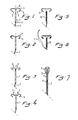
- Figures 1, 2, 3 and 4 show four different possible embodiments of a device according to the invention.
- Each device consists of a stem 1 with two arms 2, 3 projecting at either side at the upper extremity.
- the device according to Figure 1 shows two arms 2, 3 consisting of a first part 4 which is straight and is then bent through an angle of the order of magnitude of 35°, and thereafter a second part or extension 5 which points in the direction of the stem 1 and has a length of approximately 6 mm.
- the hook over which the extremities of the arms 2,3 are bent is circular and in this case has an inner diameter of 2 mm and an outer diameter of approxi mately 4 mm.
- the thickness of the small arms and the bent extensions is approximately 1.1 mm.
- the thickness of the stem is approximately 1.5 mm round.
- the small arms as well as the stem are circular.
- a small hole 6 through which a small wire 7 is fitted is attached near the lower end of the stem 1.
- the device is provided with a thickening 8 present at the upper side of the device at the point where the stem 1 is fastened to the arms 2,3.
- the angle which the straight part 5 of one of the arms 2,3 forms with the stem 1 is in this case 90°.
- Figure 2 shows a device which also consists of a stem 1 with a small hole 6 through which a small wire 7 extends near the lower side.
- the first part 9 of the arms 2,3 is in this case not straight but slightly bent upwards.
- Figure 3 shows a device according to the invention in which the angle through which the extremities of the two arms 2, 3 are bent is sharp and has approximately a V shape.
- Figure 4 shows a device according to the invention in which the angle between the first straight part 5 of the arms 2, 3 and the stem is greater than 90° and the arms thus extend obliquely upwards relative to the stem 1.
- Figure 5 shows a device according to the invention such as is represented in Figure 1 in which a wire 10 is wound round the stem.
- this is a copper wire used as a means for introducing copper ions into the uterus during a lengthy period.
- Figure 6 furthermore shows the possibility of fitting wires not only to the stem but also to the bent parts or extensions 5 of the device; as a result copper ions will be present even at the sidewall of the uterine cavity.
- other therapeutic or hormonal agents can be attached at the outer surface of the stem 1 and/or arm parts 4, 5.
- Figure 7 shows the downwardly folded state of the device according to the invention; this is the position of the arms when these are pushed into the uterine cervix by means of a small tube 11.
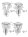
- Figures 8, 9 and 10 show a cross-section of a uterus 12 with the fallopian tubes 13, the uterine cavity 14 and the cervix 15.
- Figure 8 shows the device according to the invention at the instant at which this is pushed into the cervix 15 by means of the small tube 11.
- the arms 2, 3 will be bent downwards away after which the small tube is pushed with the device through the cervix 15 to arrive, subsequently, in the uterine cavity.
- the arms 2, 3 will subsequently have sufficient space near the upper side of the uterine cavity for springing back into the original state sideways and upwards.
- the device When the small tube is then taken out of the uterine cavity again the device will remain in the uterine cavity because the arms 2, 3 which are extended sideways will press against the sidewalls of the uterine cavity and as a result of this will remain clamped between the sidewalls 17, 18 of the uterine cavity.
- Figure 11 shows the uterus 12 in the state in which it is contracted; the state of the uterus at the instant at which it is relaxed is at the same time shown in dashed lines.
- the arms 2, 3 of the device In the state in which the uterus is contracted the arms 2, 3 of the device will be somewhat bent and, such as represented here, slightly bent upwards and the bent parts 5 of the arms 2, 3 will possibly be pushed slightly inwards, i.e. the extension 5 towards the first parts 4 of the arms.
- this device in the relaxed state of the uterus this device, as represented in Figure 11, will resume the position as shown in Figure 10.
- the device can be easily removed at a certain desired instant by means of the small wire 7.
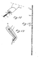
- Figure 12 shows a view of a uterus and in particular that section which contains the cervix.
- a small section of the device and also the extensions 5 of the arms 2, 3 together with the small tube 11 for introducing the device into the uterine cavity are still inserted in the cervical os which is somewhat slit-shaped.
- Figure 13 shows a cross-section through the uterus such as represented in Figures 8, 9 and 10 in a direction perpendicular to the section represented in those figures.
- the uterus shows flexion and the device must not be so long that the lowermost end reaches the section of the inner uterine cavity which is rich in nerves.
- Figure 14 shows a further small tube with which the device can be inserted in the uterine cavity and to which certain indicators can be attached such as, for example, a tape measure with a number of coloured rings 16.
- the device according to the invention has great advantages over the devices known to date, in that the device according to the invention is adapted to the shape of the uterine cavity and thereby takes account of the size of the uterine cavity in vivo because the latter may be smaller, as a result of contraction, than measured after it has been removed from the body.
- the device according to the invention will easily remain within the cavity, even when the uterus contracts, without the device being pressed against the walls of the cavity in a manner such that parts of the device are pushed into the wall. Even the layer of mucous membrane in the uterine cavity is hardly damaged by the device according to the invention.
- the device is small in size, and therefore lightweight, the weight will hardly exert forces on the device which could be a cause for the device to be rejected or at least to fall out of the cavity.
- a further advantage of the small size is that the outer surface area of the device is very small with the result that fewer bacteria may be present on the device. Specifically, it is generally known that some bacteria such as Staphylococcus epididermidis can multiply on the surface of plastics. Only in the first month after insertion of the device into the uterus may there be somewhat more bleeding than normal, because the layer of mucous membrane and the muscular tissue of the uterine cavity may be slightly irritated by the insertion.
- the size of the uterine cavity can be taken into account and the appropriate size of the device determined beforehand. It has been found that at least in Europe three standard dimensions are sufficient, that is to say a length of the stem of 28 mm, 30 mm and 32 mm with an appropriate maximum width of the device of 20 mm, 24 mm and 28 mm, respectively. Two further dimensions may optionally be added to this, that is to say: stem length 26 mm and 34 mm with the appropriate dimensions for the maximum width of 16 mm and 32 mm, respectively.
Abstract
Description
- The invention relates to a device which is to be placed in the uterus or uterine cavity and to which or in which certain substances such as metal ions, hormones or therapeutic substances which are to be effective in the uterus for a certain time can be attached, and which device comprises a stem with resilient or flexible arms projecting on either side of the stem near or at one extremity thereof, and the extremity of each of the two arms is bent through an angle greater than 90° so that the extremities point towards the stem and the arms are thus built up of three parts, i.e. a first part and a second part or extension, and a bent piece between them.
- Devices which can be placed in the uterus for precluding pregnancy and which are known in medical circles by the name "intrauterine device" or "IUD" are generally known. A device of this type which essentially consists of a "T"-shaped body is described in U.S. Patent 3,533,406. This T-shaped body is to be placed entirely in the uterus. The transverse bar then presses against the fundus or right upper section of the uterus, and the lowermost extremity of the stem is directed towards the orifice of the cervix. It has been found that this device is unsatisfactory in a relatively large number of cases. In a number of cases the device is rejected and in a large number of cases excessive bleeding occurs and such a device is experienced as being painful. Furthermore, in a relatively large number of cases pregnancy is not prevented. The fact that this device is inappropriate is attributed to the extremities of the transverse bars becoming immobilized in the uterine wall, or being at least pushed in, which results in damage to the endometrium or the mucous membrane layer.
- U.S. Patent 4,045,131 describes a device likewise having a T-shaped appearance. The extremities of the transverse bar are provided with extensions bent through an angle and directed to the stem. The upper transverse bar is, however, bent towards the outside and downwards and the dimensions and shape of the device are such that the device becomes secured as optimally as possible in the uterine cavity. The transverse bar is bent downwards, and the extremities near the bent piece thus point downwards at an angle, to prevent the device from sliding downwards to the uterine neck or cervix. If, for example, the uterus contracts, the fundus will press on the top of the device and the extremities of the transverse bar will therefore be pushed into the wall of the uterine cavity. To prevent the extremities from penetrating the wall extensions are made at the extremities with the result that the area of pressure is increased. This known device also has the drawback that pain may occur in a relatively large number of cases, the device is rejected and bleeding occurs.
- Measurements with measuring instruments developed specifically for this purpose have shown that the uterine cavity in vivo is smaller than assumed hitherto. All of the devices, known to date, which are to be placed in the uterus are shaped such that the best possible anchorage in the uterine cavity is obtained. For this purpose, the dimensions of these known devices are all too large. This is also very probably the reason why pain is felt regularly and why there is often bleeding. This is partially caused by damage to the wall and the tissue at the inner side of the uterine cavity. Another reason may be that the stem extremity of the device projects into the cervix, especially during the period when the uterus contracts greatly.
- The invention has as its object a device which can be placed in the uterine cavity and which has or can have dimensions such that the inner wall of the uterine cavity is hardly irritated, if at all.
- This object is achieved with a device according to the invention in that the three parts of each arm together form an arrow the legs of which consist of the first part and the second part or extension, these parts being compliantly connected to each other by the bent piece, and the direction of the first part near the bent piece being horizontal or upward. It has been found that these measures make it possible to construct a device which approximately corresponds to the dimensions of the uterine cavity in vivo, or is even smaller, without this device being rejected. The prejudice that a device must be anchored as optimally as possible in the uterine wall was found to be incorrect. Another great advantage of the device according to the invention is that there is hardly any bleeding outside the first period beyond the normally occurring bleeding. The angle enclosed by the first part of the arm and the second part or extension is preferably smaller than 60° so that these extremities can easily slide into the narrowing leading to the fallopian tubes, which is of particular importance when the uterus contracts greatly.
- The arrow shape formed by the first part, the second part or extension and the bent part of each arm is preferably a shape between a V and a U. This is particularly important when inserting the device and also when the device is placed in the uterine cavity. With the correct shape the bent extremities of the arms will not easily hook into the wall of the uterine cavity or get stuck. By choosing the position of the extensions of the arms such that they extend approximately parallel to the sidewalls of the uterine cavity it is achieved that the extremities of the arms slide easily along these walls which is particularly important when the uterus contracts. Due to the fact that the device is manufactured of flexible material the two legs of the arrow can moreover easily move towards each other so that the extensions can slide even better along the sidewalls of the uterine cavity without damaging the latter.
- In a preferred embodiment of the device according to the invention the point at which the arms are fastened to the stem is reinforced so that the arms resume the original position more easily once the device has been inserted in the uterine cavity. This is because it is important that the arms resume the correct position after insertion.
- The thickness of the small arms and the exten sions of the small arms is preferably less than 1.5 mm and, when manufactured of plastic material, preferably 1.1 mm or more. It is important that the small arm is so thin in order that the extensions can be sufficiently compliant relative to the first part of the small arms. The small arms should be less thin at the other side because there may otherwise be plastic deformation, and the device will no longer be capable of returning to the original state. In particular, it is very important that the small arms are directed sideways when the device is inserted in the uterine cavity. Another reason why it is important to make the small arms as thin as possible is the fact that bacteria may become settled on the surface of the plastic. Thin round arms have a small surface area. The thickness of the stem of the device is preferably smaller than 2 mm and is preferably of the order of 1.5 mm. In addition, two contradictory interests are to be served, namely the thinner the stem the less is the risk of bacteria; the thicker the stem the more metal, hormones or therapeutic substances can be attached to the stem.
- Measurements on the uterine cavity in vivo have shown that the width of each device ought to be adapted to the dimensions of a uterine cavity. It has generally been found, however, that it is sufficient, at least for European women, to have a limited number of different dimensions of the device. In principle, three standard dimensions for the maximum width of the devices are sufficient, i.e. 20 mm, 24 mm and 28 mm. This width is coupled with a maximum length of the stem of 28 mm, 30 mm and 32 mm, respectively. This length of the stem is more or less the maximum acceptable length because the lower end of the stem must not reach the region of the internal os which is rich in nerves. For this purpose account is to be taken of the contraction of the uterus and the flexion which most uteri have at the transition of the uterine cavity into the cervix.
- It has been found in practice that, when a limited number of standard dimensions of the device according to the invention is taken as a starting point and the uterine cavity was measured beforehand, the accompanying symptoms such as excessive bleeding, pain and rejection of the device can be prevented virtually entirely when the correct dimension of the device is used for a certain measured width of a uterine cavity.
- The invention will be illustrated in detail by reference to the drawing, in which:
- Figures 1, 2, 3 and 4 show four different possible embodiments of the device according to the invention;
- Figures 5 and 6 show a device as represented in Figure 1, provided with copper wire;
- Figure 7 shows the device according to Figure 1 in which the small arms are folded downwards;
- Figures 8, 9 and 10 show the uterine cavity in cross-section with the device according to the invention during insertion into the uterine cavity;
- Figure 11 shows the uterus in cross-section in two positions with a device according to the invention;
- Figure 12 shows a view of the uterus near the cervix;
- Figure 13 shows a cross-section through a uterus perpendicular to the section as represented in Figures 8, 9 and 10;
- Figure 14 shows a view of a small bar for insertion of a device according to the invention.
- Figures 1, 2, 3 and 4 show four different possible embodiments of a device according to the invention. Each device consists of a
stem 1 with twoarms arms extension 5 which points in the direction of thestem 1 and has a length of approximately 6 mm. The hook over which the extremities of thearms stem 1. The device is provided with a thickening 8 present at the upper side of the device at the point where thestem 1 is fastened to thearms straight part 5 of one of thearms stem 1 is in this case 90°. - Figure 2 shows a device which also consists of a
stem 1 with a small hole 6 through which a small wire 7 extends near the lower side. Thefirst part 9 of thearms arms straight part 5 of thearms stem 1. - Figure 5 shows a device according to the invention such as is represented in Figure 1 in which a wire 10 is wound round the stem. In this case, this is a copper wire used as a means for introducing copper ions into the uterus during a lengthy period. Figure 6 furthermore shows the possibility of fitting wires not only to the stem but also to the bent parts or
extensions 5 of the device; as a result copper ions will be present even at the sidewall of the uterine cavity. In the same manner other therapeutic or hormonal agents can be attached at the outer surface of thestem 1 and/orarm parts 4, 5. For this purpose it should be possible to attach wires at the outer surface of the device which are impregnated with the desired agent. Figure 7 shows the downwardly folded state of the device according to the invention; this is the position of the arms when these are pushed into the uterine cervix by means of asmall tube 11. - Figures 8, 9 and 10 show a cross-section of a
uterus 12 with thefallopian tubes 13, theuterine cavity 14 and thecervix 15. Figure 8 shows the device according to the invention at the instant at which this is pushed into the cervix 15 by means of thesmall tube 11. Thearms arms arms - Figure 11 shows the
uterus 12 in the state in which it is contracted; the state of the uterus at the instant at which it is relaxed is at the same time shown in dashed lines. In the state in which the uterus is contracted thearms bent parts 5 of thearms extension 5 towards the first parts 4 of the arms. In the relaxed state of the uterus this device, as represented in Figure 11, will resume the position as shown in Figure 10. The device can be easily removed at a certain desired instant by means of the small wire 7. - Figure 12 shows a view of a uterus and in particular that section which contains the cervix. A small section of the device and also the
extensions 5 of thearms small tube 11 for introducing the device into the uterine cavity are still inserted in the cervical os which is somewhat slit-shaped. - Figure 13 shows a cross-section through the uterus such as represented in Figures 8, 9 and 10 in a direction perpendicular to the section represented in those figures. As is often the case, the uterus shows flexion and the device must not be so long that the lowermost end reaches the section of the inner uterine cavity which is rich in nerves. Figure 14 shows a further small tube with which the device can be inserted in the uterine cavity and to which certain indicators can be attached such as, for example, a tape measure with a number of coloured rings 16.
- The device according to the invention has great advantages over the devices known to date, in that the device according to the invention is adapted to the shape of the uterine cavity and thereby takes account of the size of the uterine cavity in vivo because the latter may be smaller, as a result of contraction, than measured after it has been removed from the body. The device according to the invention will easily remain within the cavity, even when the uterus contracts, without the device being pressed against the walls of the cavity in a manner such that parts of the device are pushed into the wall. Even the layer of mucous membrane in the uterine cavity is hardly damaged by the device according to the invention. As a result of the fact that the device is small in size, and therefore lightweight, the weight will hardly exert forces on the device which could be a cause for the device to be rejected or at least to fall out of the cavity. A further advantage of the small size is that the outer surface area of the device is very small with the result that fewer bacteria may be present on the device. Specifically, it is generally known that some bacteria such as Staphylococcus epididermidis can multiply on the surface of plastics. Only in the first month after insertion of the device into the uterus may there be somewhat more bleeding than normal, because the layer of mucous membrane and the muscular tissue of the uterine cavity may be slightly irritated by the insertion.
- Since it is possible at present to determine and measure very accurately the inner dimensions of the uterine cavity in a living individual the size of the uterine cavity can be taken into account and the appropriate size of the device determined beforehand. It has been found that at least in Europe three standard dimensions are sufficient, that is to say a length of the stem of 28 mm, 30 mm and 32 mm with an appropriate maximum width of the device of 20 mm, 24 mm and 28 mm, respectively. Two further dimensions may optionally be added to this, that is to say: stem length 26 mm and 34 mm with the appropriate dimensions for the maximum width of 16 mm and 32 mm, respectively.
Claims (9)
Priority Applications (1)
| Application Number | Priority Date | Filing Date | Title |
|---|---|---|---|
| AT87202529T ATE63055T1 (en) | 1986-12-17 | 1987-12-15 | DEVICE FOR INSERTION IN THE UTERUS. |
Applications Claiming Priority (2)
| Application Number | Priority Date | Filing Date | Title |
|---|---|---|---|
| NL8603216A NL8603216A (en) | 1986-12-17 | 1986-12-17 | DEVICE FOR PLACING IN THE UTERUS. |
| NL8603216 | 1986-12-17 |
Publications (3)
| Publication Number | Publication Date |
|---|---|
| EP0274794A2 true EP0274794A2 (en) | 1988-07-20 |
| EP0274794A3 EP0274794A3 (en) | 1988-08-03 |
| EP0274794B1 EP0274794B1 (en) | 1991-05-02 |
Family
ID=19849012
Family Applications (1)
| Application Number | Title | Priority Date | Filing Date |
|---|---|---|---|
| EP87202529A Expired - Lifetime EP0274794B1 (en) | 1986-12-17 | 1987-12-15 | Device to be placed in the uterus |
Country Status (10)
| Country | Link |
|---|---|
| EP (1) | EP0274794B1 (en) |
| CN (1) | CN1014203B (en) |
| AT (1) | ATE63055T1 (en) |
| AU (1) | AU1087088A (en) |
| CA (1) | CA1325564C (en) |
| DE (1) | DE3769777D1 (en) |
| ES (1) | ES2022317B3 (en) |
| GR (1) | GR3002228T3 (en) |
| NL (1) | NL8603216A (en) |
| WO (1) | WO1988004544A1 (en) |
Cited By (1)
| Publication number | Priority date | Publication date | Assignee | Title |
|---|---|---|---|---|
| EP3446664A1 (en) | 2017-08-21 | 2019-02-27 | Karl-Heinz Kurz | Intrauterine device |
Families Citing this family (11)
| Publication number | Priority date | Publication date | Assignee | Title |
|---|---|---|---|---|
| US4931175A (en) * | 1988-09-07 | 1990-06-05 | Lenox Institute For Research, Inc. | Water clarifying apparatus |
| ES2292206T3 (en) * | 1997-10-10 | 2008-03-01 | Bioniche Life Sciences Inc. | ADMINISTRATION SYSTEM OF PHARMACOS. |
| US6759393B1 (en) | 1999-04-12 | 2004-07-06 | Pfizer Inc. | Growth hormone and growth hormone releasing hormone compositions |
| EP2140860A1 (en) * | 2008-07-03 | 2010-01-06 | Bayer Schering Pharma Oy | An improved method of contraception |
| US10028858B2 (en) | 2011-07-11 | 2018-07-24 | Medicines360 | Intrauterine systems, IUD insertion devices, and related methods and kits therefor |
| ES2803579T3 (en) | 2014-09-04 | 2021-01-28 | Memic Innovative Surgery Ltd | Device and system including mechanical arms |
| SI3190942T1 (en) | 2015-09-04 | 2020-10-30 | Memic Innovative Surgery Ltd. | Actuation of a device comprising mechanical arms |
| SI3219283T1 (en) | 2016-03-09 | 2021-04-30 | Memic Innovative Surgery Ltd. | Modular surgical device comprising mechanical arms |
| CN106137346A (en) * | 2016-07-28 | 2016-11-23 | 山东中医药大学附属医院 | A kind of degradable uterine cavity Anti-adhering device |
| US10973592B2 (en) | 2017-03-09 | 2021-04-13 | Memie Innovative Surgery Ltd. | Control console for surgical device with mechanical arms |
| US11779410B2 (en) | 2017-03-09 | 2023-10-10 | Momentis Surgical Ltd | Control console including an input arm for control of a surgical mechanical arm |
Citations (4)
| Publication number | Priority date | Publication date | Assignee | Title |
|---|---|---|---|---|
| US3467089A (en) * | 1967-02-14 | 1969-09-16 | Hollister Inc | Intrauterine contraceptive device (iud) |
| US4054131A (en) * | 1976-08-10 | 1977-10-18 | International Pregnancy Advisory Services | Intrauterine contraceptive device |
| FR2427088A1 (en) * | 1978-05-30 | 1979-12-28 | Thouvenin Rene | Intra-uterine contraception device - has arms with top and bottom branches bearing against uterus wall |
| GB1568419A (en) * | 1976-08-11 | 1980-05-29 | Pope M | Improvements in iucds |
-
1986
- 1986-12-17 NL NL8603216A patent/NL8603216A/en not_active Application Discontinuation
-
1987
- 1987-12-15 EP EP87202529A patent/EP0274794B1/en not_active Expired - Lifetime
- 1987-12-15 DE DE8787202529T patent/DE3769777D1/en not_active Expired - Lifetime
- 1987-12-15 ES ES87202529T patent/ES2022317B3/en not_active Expired - Lifetime
- 1987-12-15 AT AT87202529T patent/ATE63055T1/en not_active IP Right Cessation
- 1987-12-16 CA CA000554464A patent/CA1325564C/en not_active Expired - Lifetime
- 1987-12-17 WO PCT/EP1987/000791 patent/WO1988004544A1/en unknown
- 1987-12-17 CN CN87108401A patent/CN1014203B/en not_active Expired
- 1987-12-17 AU AU10870/88A patent/AU1087088A/en not_active Abandoned
-
1991
- 1991-07-02 GR GR91400927T patent/GR3002228T3/en unknown
Patent Citations (4)
| Publication number | Priority date | Publication date | Assignee | Title |
|---|---|---|---|---|
| US3467089A (en) * | 1967-02-14 | 1969-09-16 | Hollister Inc | Intrauterine contraceptive device (iud) |
| US4054131A (en) * | 1976-08-10 | 1977-10-18 | International Pregnancy Advisory Services | Intrauterine contraceptive device |
| GB1568419A (en) * | 1976-08-11 | 1980-05-29 | Pope M | Improvements in iucds |
| FR2427088A1 (en) * | 1978-05-30 | 1979-12-28 | Thouvenin Rene | Intra-uterine contraception device - has arms with top and bottom branches bearing against uterus wall |
Cited By (1)
| Publication number | Priority date | Publication date | Assignee | Title |
|---|---|---|---|---|
| EP3446664A1 (en) | 2017-08-21 | 2019-02-27 | Karl-Heinz Kurz | Intrauterine device |
Also Published As
| Publication number | Publication date |
|---|---|
| WO1988004544A1 (en) | 1988-06-30 |
| ATE63055T1 (en) | 1991-05-15 |
| GR3002228T3 (en) | 1992-12-30 |
| AU1087088A (en) | 1988-07-15 |
| CN87108401A (en) | 1988-06-29 |
| EP0274794B1 (en) | 1991-05-02 |
| DE3769777D1 (en) | 1991-06-06 |
| EP0274794A3 (en) | 1988-08-03 |
| ES2022317B3 (en) | 1991-12-01 |
| CN1014203B (en) | 1991-10-09 |
| CA1325564C (en) | 1993-12-28 |
| NL8603216A (en) | 1988-07-18 |
Similar Documents
| Publication | Publication Date | Title |
|---|---|---|
| CA1046881A (en) | Intrauterine contraceptive device of c or omega form with tubular inserter and method of placement | |
| US3937217A (en) | Intrauterine contraceptive device | |
| US5146931A (en) | Device to be placed in the uterus | |
| EP0274794B1 (en) | Device to be placed in the uterus | |
| US3881475A (en) | Intra-uterine contraceptive device | |
| US4372302A (en) | Instrument for retrieval of retracted threads of intrauterine contraceptive devices | |
| US6216698B1 (en) | Flexible pessary | |
| US5494047A (en) | Intrauterine contraceptive device | |
| JPH10510444A (en) | Insertion device used to place intrauterine devices | |
| US4111196A (en) | Intrauterine contraceptive device of c or omega form with tubular inserter and method of placement | |
| US3993058A (en) | Intrauterine device with seeker for finding the cervical os and housing member for fitting device in an inserter | |
| WO2007075086A1 (en) | Intrauterine device and applicator for introducing the same into the uterus | |
| JPS62500433A (en) | Variable size intrauterine pessary | |
| US4117839A (en) | Intrauterine device | |
| US4018220A (en) | Method of insertion for intrauterine device of C or omega form with tubular inserter | |
| US4658810A (en) | Method of contraception and a device therefor | |
| IE57545B1 (en) | Assembly of intra-uterine contraceptive device and inserter | |
| US4841991A (en) | Intrauterine contraceptive device | |
| HU200554B (en) | Intra-uterine contraceptive device | |
| US7926488B2 (en) | Frame of an intrauterine system | |
| US4830025A (en) | Intrauterine contraceptive device | |
| JPS581290Y2 (en) | Intrauterine contraceptive device insertion tool | |
| US1129657A (en) | Uterine applicator. | |
| WO2012087339A2 (en) | Intrauterine device string | |
| JPS62500222A (en) | Contraceptive pessary insertion device |
Legal Events
| Date | Code | Title | Description |
|---|---|---|---|
| PUAI | Public reference made under article 153(3) epc to a published international application that has entered the european phase |
Free format text: ORIGINAL CODE: 0009012 |
|
| PUAL | Search report despatched |
Free format text: ORIGINAL CODE: 0009013 |
|
| AK | Designated contracting states |
Kind code of ref document: A2 Designated state(s): AT BE CH DE ES FR GB GR IT LI LU NL SE |
|
| AK | Designated contracting states |
Kind code of ref document: A3 Designated state(s): AT BE CH DE ES FR GB GR IT LI LU NL SE |
|
| 17P | Request for examination filed |
Effective date: 19881115 |
|
| 17Q | First examination report despatched |
Effective date: 19900620 |
|
| GRAA | (expected) grant |
Free format text: ORIGINAL CODE: 0009210 |
|
| AK | Designated contracting states |
Kind code of ref document: B1 Designated state(s): AT BE CH DE ES FR GB GR IT LI LU NL SE |
|
| PG25 | Lapsed in a contracting state [announced via postgrant information from national office to epo] |
Ref country code: IT Free format text: LAPSE BECAUSE OF FAILURE TO SUBMIT A TRANSLATION OF THE DESCRIPTION OR TO PAY THE FEE WITHIN THE PRE;WARNING: LAPSES OF ITALIAN PATENTS WITH EFFECTIVE DATE BEFORE 2007 MAY HAVE OCCURRED AT ANY TIME BEFORE 2007. THE CORRECT EFFECTIVE DATE MAY BE DIFFERENT FROM THE ONE RECORDED.SCRIBED TIME-LIMIT Effective date: 19910502 |
|
| REF | Corresponds to: |
Ref document number: 63055 Country of ref document: AT Date of ref document: 19910515 Kind code of ref document: T |
|
| REF | Corresponds to: |
Ref document number: 3769777 Country of ref document: DE Date of ref document: 19910606 |
|
| ET | Fr: translation filed | ||
| PG25 | Lapsed in a contracting state [announced via postgrant information from national office to epo] |
Ref country code: LU Free format text: LAPSE BECAUSE OF NON-PAYMENT OF DUE FEES Effective date: 19911231 |
|
| PLBE | No opposition filed within time limit |
Free format text: ORIGINAL CODE: 0009261 |
|
| STAA | Information on the status of an ep patent application or granted ep patent |
Free format text: STATUS: NO OPPOSITION FILED WITHIN TIME LIMIT |
|
| 26N | No opposition filed | ||
| REG | Reference to a national code |
Ref country code: GR Ref legal event code: FG4A Free format text: 3002228 |
|
| EAL | Se: european patent in force in sweden |
Ref document number: 87202529.1 |
|
| PGFP | Annual fee paid to national office [announced via postgrant information from national office to epo] |
Ref country code: GR Payment date: 19981007 Year of fee payment: 12 |
|
| PGFP | Annual fee paid to national office [announced via postgrant information from national office to epo] |
Ref country code: CH Payment date: 19981215 Year of fee payment: 12 |
|
| PG25 | Lapsed in a contracting state [announced via postgrant information from national office to epo] |
Ref country code: CH Free format text: LAPSE BECAUSE OF NON-PAYMENT OF DUE FEES Effective date: 19991231 Ref country code: GR Free format text: LAPSE BECAUSE OF NON-PAYMENT OF DUE FEES Effective date: 19991231 Ref country code: LI Free format text: LAPSE BECAUSE OF NON-PAYMENT OF DUE FEES Effective date: 19991231 |
|
| EUG | Se: european patent has lapsed | ||
| REG | Reference to a national code |
Ref country code: FR Ref legal event code: ST |
|
| REG | Reference to a national code |
Ref country code: FR Ref legal event code: D3 |
|
| REG | Reference to a national code |
Ref country code: GB Ref legal event code: IF02 |
|
| PGFP | Annual fee paid to national office [announced via postgrant information from national office to epo] |
Ref country code: AT Payment date: 20041230 Year of fee payment: 18 |
|
| PG25 | Lapsed in a contracting state [announced via postgrant information from national office to epo] |
Ref country code: AT Free format text: LAPSE BECAUSE OF NON-PAYMENT OF DUE FEES Effective date: 20051215 |
|
| PGFP | Annual fee paid to national office [announced via postgrant information from national office to epo] |
Ref country code: GB Payment date: 20061227 Year of fee payment: 20 Ref country code: SE Payment date: 20061227 Year of fee payment: 20 |
|
| PGFP | Annual fee paid to national office [announced via postgrant information from national office to epo] |
Ref country code: ES Payment date: 20061229 Year of fee payment: 20 Ref country code: NL Payment date: 20061229 Year of fee payment: 20 |
|
| PGFP | Annual fee paid to national office [announced via postgrant information from national office to epo] |
Ref country code: BE Payment date: 20070117 Year of fee payment: 20 |
|
| PGFP | Annual fee paid to national office [announced via postgrant information from national office to epo] |
Ref country code: DE Payment date: 20070119 Year of fee payment: 20 |
|
| BE20 | Be: patent expired |
Owner name: *KURZ KARL-HEINZ Effective date: 20071215 |
|
| REG | Reference to a national code |
Ref country code: GB Ref legal event code: PE20 |
|
| PG25 | Lapsed in a contracting state [announced via postgrant information from national office to epo] |
Ref country code: NL Free format text: LAPSE BECAUSE OF EXPIRATION OF PROTECTION Effective date: 20071215 |
|
| NLV7 | Nl: ceased due to reaching the maximum lifetime of a patent |
Effective date: 20071215 |
|
| EUG | Se: european patent has lapsed | ||
| REG | Reference to a national code |
Ref country code: ES Ref legal event code: FD2A Effective date: 20071217 |
|
| PG25 | Lapsed in a contracting state [announced via postgrant information from national office to epo] |
Ref country code: ES Free format text: LAPSE BECAUSE OF EXPIRATION OF PROTECTION Effective date: 20071217 Ref country code: GB Free format text: LAPSE BECAUSE OF EXPIRATION OF PROTECTION Effective date: 20071214 |
|
| PGFP | Annual fee paid to national office [announced via postgrant information from national office to epo] |
Ref country code: FR Payment date: 20061227 Year of fee payment: 20 |