EP0274479B1 - Process for the separation and isolation of shaped catalyst-type particles by length - Google Patents
Process for the separation and isolation of shaped catalyst-type particles by length Download PDFInfo
- Publication number
- EP0274479B1 EP0274479B1 EP19870902239 EP87902239A EP0274479B1 EP 0274479 B1 EP0274479 B1 EP 0274479B1 EP 19870902239 EP19870902239 EP 19870902239 EP 87902239 A EP87902239 A EP 87902239A EP 0274479 B1 EP0274479 B1 EP 0274479B1
- Authority
- EP
- European Patent Office
- Prior art keywords
- particles
- length
- catalyst
- millimeters
- zone
- Prior art date
- Legal status (The legal status is an assumption and is not a legal conclusion. Google has not performed a legal analysis and makes no representation as to the accuracy of the status listed.)
- Expired - Lifetime
Links
- 239000002245 particle Substances 0.000 title claims abstract description 175
- 238000000034 method Methods 0.000 title claims description 41
- 238000000926 separation method Methods 0.000 title description 15
- 238000002955 isolation Methods 0.000 title description 2
- 239000003054 catalyst Substances 0.000 claims abstract description 109
- 238000007373 indentation Methods 0.000 claims abstract description 21
- 239000000203 mixture Substances 0.000 claims abstract description 17
- 230000008929 regeneration Effects 0.000 claims description 19
- 238000011069 regeneration method Methods 0.000 claims description 19
- PXHVJJICTQNCMI-UHFFFAOYSA-N Nickel Chemical compound [Ni] PXHVJJICTQNCMI-UHFFFAOYSA-N 0.000 claims description 18
- 229930195733 hydrocarbon Natural products 0.000 claims description 16
- 150000002430 hydrocarbons Chemical class 0.000 claims description 16
- PNEYBMLMFCGWSK-UHFFFAOYSA-N aluminium oxide Inorganic materials [O-2].[O-2].[O-2].[Al+3].[Al+3] PNEYBMLMFCGWSK-UHFFFAOYSA-N 0.000 claims description 11
- 229910052751 metal Inorganic materials 0.000 claims description 11
- 239000002184 metal Substances 0.000 claims description 11
- VYPSYNLAJGMNEJ-UHFFFAOYSA-N Silicium dioxide Chemical compound O=[Si]=O VYPSYNLAJGMNEJ-UHFFFAOYSA-N 0.000 claims description 10
- 229910052759 nickel Inorganic materials 0.000 claims description 9
- 150000002739 metals Chemical class 0.000 claims description 8
- 239000002253 acid Substances 0.000 claims description 6
- 229910001385 heavy metal Inorganic materials 0.000 claims description 6
- 239000000377 silicon dioxide Substances 0.000 claims description 5
- OKTJSMMVPCPJKN-UHFFFAOYSA-N Carbon Chemical compound [C] OKTJSMMVPCPJKN-UHFFFAOYSA-N 0.000 claims description 4
- 229910052799 carbon Inorganic materials 0.000 claims description 4
- 238000012545 processing Methods 0.000 claims description 4
- ZOKXTWBITQBERF-UHFFFAOYSA-N Molybdenum Chemical compound [Mo] ZOKXTWBITQBERF-UHFFFAOYSA-N 0.000 claims description 3
- 229910017052 cobalt Inorganic materials 0.000 claims description 3
- 239000010941 cobalt Substances 0.000 claims description 3
- GUTLYIVDDKVIGB-UHFFFAOYSA-N cobalt atom Chemical compound [Co] GUTLYIVDDKVIGB-UHFFFAOYSA-N 0.000 claims description 3
- 238000002386 leaching Methods 0.000 claims description 3
- 239000002808 molecular sieve Substances 0.000 claims description 3
- 229910052750 molybdenum Inorganic materials 0.000 claims description 3
- 239000011733 molybdenum Substances 0.000 claims description 3
- URGAHOPLAPQHLN-UHFFFAOYSA-N sodium aluminosilicate Chemical compound [Na+].[Al+3].[O-][Si]([O-])=O.[O-][Si]([O-])=O URGAHOPLAPQHLN-UHFFFAOYSA-N 0.000 claims description 3
- 239000002594 sorbent Substances 0.000 claims description 3
- WFKWXMTUELFFGS-UHFFFAOYSA-N tungsten Chemical compound [W] WFKWXMTUELFFGS-UHFFFAOYSA-N 0.000 claims description 3
- 229910052721 tungsten Inorganic materials 0.000 claims description 3
- 239000010937 tungsten Substances 0.000 claims description 3
- RTAQQCXQSZGOHL-UHFFFAOYSA-N Titanium Chemical compound [Ti] RTAQQCXQSZGOHL-UHFFFAOYSA-N 0.000 claims description 2
- 229910044991 metal oxide Inorganic materials 0.000 claims description 2
- 150000004706 metal oxides Chemical class 0.000 claims description 2
- 239000003870 refractory metal Substances 0.000 claims description 2
- 229910052719 titanium Inorganic materials 0.000 claims description 2
- 239000010936 titanium Substances 0.000 claims description 2
- 230000003197 catalytic effect Effects 0.000 claims 1
- 238000010438 heat treatment Methods 0.000 claims 1
- 239000000463 material Substances 0.000 description 32
- 238000009826 distribution Methods 0.000 description 16
- 239000006187 pill Substances 0.000 description 14
- 239000004215 Carbon black (E152) Substances 0.000 description 8
- 238000000605 extraction Methods 0.000 description 6
- 230000005484 gravity Effects 0.000 description 6
- 238000012216 screening Methods 0.000 description 6
- 229910052720 vanadium Inorganic materials 0.000 description 6
- LEONUFNNVUYDNQ-UHFFFAOYSA-N vanadium atom Chemical compound [V] LEONUFNNVUYDNQ-UHFFFAOYSA-N 0.000 description 6
- XEEYBQQBJWHFJM-UHFFFAOYSA-N Iron Chemical compound [Fe] XEEYBQQBJWHFJM-UHFFFAOYSA-N 0.000 description 4
- KDLHZDBZIXYQEI-UHFFFAOYSA-N Palladium Chemical compound [Pd] KDLHZDBZIXYQEI-UHFFFAOYSA-N 0.000 description 4
- 238000011109 contamination Methods 0.000 description 4
- 238000004519 manufacturing process Methods 0.000 description 4
- 239000008188 pellet Substances 0.000 description 4
- BASFCYQUMIYNBI-UHFFFAOYSA-N platinum Chemical compound [Pt] BASFCYQUMIYNBI-UHFFFAOYSA-N 0.000 description 4
- 239000007858 starting material Substances 0.000 description 4
- 239000003463 adsorbent Substances 0.000 description 3
- 238000006243 chemical reaction Methods 0.000 description 3
- 238000007670 refining Methods 0.000 description 3
- 230000003716 rejuvenation Effects 0.000 description 3
- IJGRMHOSHXDMSA-UHFFFAOYSA-N Atomic nitrogen Chemical compound N#N IJGRMHOSHXDMSA-UHFFFAOYSA-N 0.000 description 2
- CURLTUGMZLYLDI-UHFFFAOYSA-N Carbon dioxide Chemical compound O=C=O CURLTUGMZLYLDI-UHFFFAOYSA-N 0.000 description 2
- 238000004517 catalytic hydrocracking Methods 0.000 description 2
- KYYSIVCCYWZZLR-UHFFFAOYSA-N cobalt(2+);dioxido(dioxo)molybdenum Chemical compound [Co+2].[O-][Mo]([O-])(=O)=O KYYSIVCCYWZZLR-UHFFFAOYSA-N 0.000 description 2
- 239000000571 coke Substances 0.000 description 2
- 239000000356 contaminant Substances 0.000 description 2
- 238000010586 diagram Methods 0.000 description 2
- 239000000428 dust Substances 0.000 description 2
- 238000002474 experimental method Methods 0.000 description 2
- -1 for example Substances 0.000 description 2
- 239000012535 impurity Substances 0.000 description 2
- 229910052742 iron Inorganic materials 0.000 description 2
- 230000001788 irregular Effects 0.000 description 2
- 230000003647 oxidation Effects 0.000 description 2
- 238000007254 oxidation reaction Methods 0.000 description 2
- 229910052763 palladium Inorganic materials 0.000 description 2
- 229910052697 platinum Inorganic materials 0.000 description 2
- 238000004513 sizing Methods 0.000 description 2
- 238000012360 testing method Methods 0.000 description 2
- XLYOFNOQVPJJNP-UHFFFAOYSA-N water Substances O XLYOFNOQVPJJNP-UHFFFAOYSA-N 0.000 description 2
- 235000011054 acetic acid Nutrition 0.000 description 1
- 125000000218 acetic acid group Chemical group C(C)(=O)* 0.000 description 1
- 238000005054 agglomeration Methods 0.000 description 1
- 230000002776 aggregation Effects 0.000 description 1
- 239000007864 aqueous solution Substances 0.000 description 1
- QVGXLLKOCUKJST-UHFFFAOYSA-N atomic oxygen Chemical compound [O] QVGXLLKOCUKJST-UHFFFAOYSA-N 0.000 description 1
- 229910002092 carbon dioxide Inorganic materials 0.000 description 1
- 239000001569 carbon dioxide Substances 0.000 description 1
- 230000015556 catabolic process Effects 0.000 description 1
- 235000015165 citric acid Nutrition 0.000 description 1
- KRKNYBCHXYNGOX-UHFFFAOYSA-N citric acid group Chemical class C(CC(O)(C(=O)O)CC(=O)O)(=O)O KRKNYBCHXYNGOX-UHFFFAOYSA-N 0.000 description 1
- WHDPTDWLEKQKKX-UHFFFAOYSA-N cobalt molybdenum Chemical compound [Co].[Co].[Mo] WHDPTDWLEKQKKX-UHFFFAOYSA-N 0.000 description 1
- 238000002485 combustion reaction Methods 0.000 description 1
- 230000003292 diminished effect Effects 0.000 description 1
- NLPVCCRZRNXTLT-UHFFFAOYSA-N dioxido(dioxo)molybdenum;nickel(2+) Chemical compound [Ni+2].[O-][Mo]([O-])(=O)=O NLPVCCRZRNXTLT-UHFFFAOYSA-N 0.000 description 1
- 238000005516 engineering process Methods 0.000 description 1
- 238000001125 extrusion Methods 0.000 description 1
- 239000012530 fluid Substances 0.000 description 1
- 239000007789 gas Substances 0.000 description 1
- 239000011261 inert gas Substances 0.000 description 1
- DDTIGTPWGISMKL-UHFFFAOYSA-N molybdenum nickel Chemical compound [Ni].[Mo] DDTIGTPWGISMKL-UHFFFAOYSA-N 0.000 description 1
- 229910052757 nitrogen Inorganic materials 0.000 description 1
- 229910000510 noble metal Inorganic materials 0.000 description 1
- 238000011022 operating instruction Methods 0.000 description 1
- 150000002902 organometallic compounds Chemical class 0.000 description 1
- 230000001590 oxidative effect Effects 0.000 description 1
- 239000001301 oxygen Substances 0.000 description 1
- 229910052760 oxygen Inorganic materials 0.000 description 1
- 238000012856 packing Methods 0.000 description 1
- 238000005453 pelletization Methods 0.000 description 1
- 238000005086 pumping Methods 0.000 description 1
- 238000000746 purification Methods 0.000 description 1
- 229910052761 rare earth metal Inorganic materials 0.000 description 1
- 150000002910 rare earth metals Chemical class 0.000 description 1
- 238000002407 reforming Methods 0.000 description 1
- 230000011218 segmentation Effects 0.000 description 1
- 239000002002 slurry Substances 0.000 description 1
- 239000000126 substance Substances 0.000 description 1
- 231100000331 toxic Toxicity 0.000 description 1
- 230000002588 toxic effect Effects 0.000 description 1
- 239000010891 toxic waste Substances 0.000 description 1
- 230000007704 transition Effects 0.000 description 1
- 229910052723 transition metal Inorganic materials 0.000 description 1
- 150000003624 transition metals Chemical class 0.000 description 1
Images




Classifications
-
- B—PERFORMING OPERATIONS; TRANSPORTING
- B01—PHYSICAL OR CHEMICAL PROCESSES OR APPARATUS IN GENERAL
- B01J—CHEMICAL OR PHYSICAL PROCESSES, e.g. CATALYSIS OR COLLOID CHEMISTRY; THEIR RELEVANT APPARATUS
- B01J37/00—Processes, in general, for preparing catalysts; Processes, in general, for activation of catalysts
-
- B—PERFORMING OPERATIONS; TRANSPORTING
- B01—PHYSICAL OR CHEMICAL PROCESSES OR APPARATUS IN GENERAL
- B01J—CHEMICAL OR PHYSICAL PROCESSES, e.g. CATALYSIS OR COLLOID CHEMISTRY; THEIR RELEVANT APPARATUS
- B01J38/00—Regeneration or reactivation of catalysts, in general
- B01J38/72—Regeneration or reactivation of catalysts, in general including segregation of diverse particles
-
- B—PERFORMING OPERATIONS; TRANSPORTING
- B03—SEPARATION OF SOLID MATERIALS USING LIQUIDS OR USING PNEUMATIC TABLES OR JIGS; MAGNETIC OR ELECTROSTATIC SEPARATION OF SOLID MATERIALS FROM SOLID MATERIALS OR FLUIDS; SEPARATION BY HIGH-VOLTAGE ELECTRIC FIELDS
- B03B—SEPARATING SOLID MATERIALS USING LIQUIDS OR USING PNEUMATIC TABLES OR JIGS
- B03B4/00—Separating by pneumatic tables or by pneumatic jigs
- B03B4/02—Separating by pneumatic tables or by pneumatic jigs using swinging or shaking tables
-
- B—PERFORMING OPERATIONS; TRANSPORTING
- B07—SEPARATING SOLIDS FROM SOLIDS; SORTING
- B07B—SEPARATING SOLIDS FROM SOLIDS BY SIEVING, SCREENING, SIFTING OR BY USING GAS CURRENTS; SEPARATING BY OTHER DRY METHODS APPLICABLE TO BULK MATERIAL, e.g. LOOSE ARTICLES FIT TO BE HANDLED LIKE BULK MATERIAL
- B07B13/00—Grading or sorting solid materials by dry methods, not otherwise provided for; Sorting articles otherwise than by indirectly controlled devices
- B07B13/02—Apparatus for grading using pockets for taking out particles from aggregates
-
- C—CHEMISTRY; METALLURGY
- C10—PETROLEUM, GAS OR COKE INDUSTRIES; TECHNICAL GASES CONTAINING CARBON MONOXIDE; FUELS; LUBRICANTS; PEAT
- C10G—CRACKING HYDROCARBON OILS; PRODUCTION OF LIQUID HYDROCARBON MIXTURES, e.g. BY DESTRUCTIVE HYDROGENATION, OLIGOMERISATION, POLYMERISATION; RECOVERY OF HYDROCARBON OILS FROM OIL-SHALE, OIL-SAND, OR GASES; REFINING MIXTURES MAINLY CONSISTING OF HYDROCARBONS; REFORMING OF NAPHTHA; MINERAL WAXES
- C10G45/00—Refining of hydrocarbon oils using hydrogen or hydrogen-generating compounds
- C10G45/02—Refining of hydrocarbon oils using hydrogen or hydrogen-generating compounds to eliminate hetero atoms without changing the skeleton of the hydrocarbon involved and without cracking into lower boiling hydrocarbons; Hydrofinishing
Definitions
- the invention relates to the separation and isolation of shaped catalyst-type particles by length. More particularly, this invention relates to length grading of generally cylindrically-shaped catalyst-type particles, and to the regeneration, rejuvenation, and manufacture of catalyst-type particles which have been subjected to length grading.
- Catalysts used in the conversion and refining of hydrocarbons, as well as desorbents or adsorbents in the hydrocarbon separation or purification industry have a desired particle length requirement.
- Fresh, or virgin catalysts, desorbents and adsorbents require segmentation into a particular particle length category in order to achieve optimum packing or reduce fixed bed pressure drop, or in the case of fluid beds achieve optimum pumping requirements.
- catalysts used in the conversion and refining of hydrocarbons become contaminated with carbonaceous deposits, known as "coke", as well as metallic deposits, such as nickel, vanadium, iron or silica which may be present in the hydrocarbon feed as organometallic compounds or as tramp impurities.
- coke carbonaceous deposits
- metallic deposits such as nickel, vanadium, iron or silica which may be present in the hydrocarbon feed as organometallic compounds or as tramp impurities.
- the spent catalyst becomes inactive and must be withdrawn from the catalyst reactor, and passed to a regenerator where coke is burned off to regenerate the catalyst, which is returned for reuse in the reactor.
- catalyst attrition i.e., the generally cylindrical catalyst particles become reduced in length to an undesirable degree.
- the presence of such shortened catalyst particles in a fixed bed reactor causes plugging of the bed and undesirable pressure buildup resulting in reduced flow and eventual shutdown of the bed.
- a 12 mesh screen square or slotted having a 1.7 millimeter opening, which is either square or rectangular, will allow a 1/16 inch (1.6mm) diameter cylindrically shaped catalyst particle through the opening, whether the catalyst is 2 millimeters or 10 millimeters in length, as long as the catalyst enters the opening on end. Accordingly, in practice, the use of screening techniques is limited to removal of catalyst dust or fines in which the catalyst L/D is less than one.
- catalyst particles having an L/D greater than one can still be too short for usage in the reactor. Most frequently it is the particles with an L/D in the range of 1.0 to 2.0 that are undesirable and cause problems necessitating disposal of the entire catalyst batch containing such particles. Not only is such disposal costly and wasteful, in view of the great expense of catalysts, including those containing noble metals and the like, but, in addition, such disposal results in pollution and toxic waste disposal problems since many such catalysts contain toxic metals, such as cobalt, nickel, and vanadium.
- the manufacturing process for shaped catalysts includes sizing and/or breaking procedures to produce a product of a desired particle length distribution.
- sizing and/or breaking procedures to produce a product of a desired particle length distribution.
- spent catalyst particle mixtures are "heterogeneous" in nature since the degree of feedstock-supplied metal contamination on each particle varies within the batch. Thus, a given batch of spent catalyst contains good catalyst particles and contaminated catalyst particles in varying degrees. However, since adequate methods are unavailable to separate the good particles from the more contaminated particles, the entire batch is often discarded.
- a given lot of catalyst may consist of two or more similarly shaped and sized particles but different in composition and individual pellet density.
- This may commonly be, for example, mixtures of hydrotreating and hydrocracking catalysts or nickel-molybdenum and cobalt-molybdenum catalysts.
- Such mixtures may be spent catalyst removed from a processing reactor or fresh catalyst which may have been inadvertently mixed during the manufacture or a handling process. These mixtures have diminished value and are commonly discarded.
- an admixture consisting essentially of shaped, generally cylindrical, free flowing, similar, catalyst-type particles all having substantially the same diameter, are separated into a first group of particles having a length to diameter ratio (L/D) greater than one and a length below a predetermined length, L1, in the range of from about 0.8 to about 24 millimeters, and a second group of particles having an L/D greater than one and a length above the predetermined length L1, by passing the catalyst admixture into a cylindrical drum having inwardly opening indentations in a cylindrical wall thereof, the indentations having a transverse diameter approximately equal to L1; rotating the drum about a longitudinal axis thereof at a speed sufficient to entrap particles in the indentations and convey the particles of the first group upwardly to a height permitting the particles to fall into a fixed, upwardly opening trough, while retaining the particles of the second group in a bottom portion of the drum; conveying the particles in the trough out a
- spent catalyst particles are deoiled, length graded and regenerated to remove carbonaceous deposits.
- spent catalyst particles are regenerated and then length graded.
- spent catalyst is deoiled, extracted with acid to remove metal contaminants, regenerated to remove carbon contaminants, and then length graded.
- similar or dissimilar, fresh, virgin, shaped catalyst, adsorbents, or desorbents are length graded to achieve homogeneous length fractions.
- spent catalyst particles can be length graded within a very narrow particle distribution range with a precision unobtainable by conventional screen techniques.
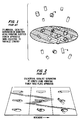
- FIG. 1 The limitations of a prior art slotted or rectangular screen are illustrated in FIG. 1 where the light pellets A have a diameter less than the narrow opening of the slotted screen.
- the dark pills B have a diameter greater than the narrow opening of the slotted screen.
- any pill with a dimension less than the narrow opening can pass through.
- all light pills (with a diameter less than the narrow opening) or all dark pills with a length less than the narrow opening can pass through.
- FIG. 1 shows that the slotted screen separation is based on a particle's smallest dimension, whereas in length grading in accordance with the present invention, separation is based upon a particle's greatest dimension.
- Another screening technique used to separate catalyst pills on a length basis employs vibrating "punched plates" as illustrated in FIG. 2 in accordance with the prior art.
- pills are axially aligned in the direction of movement and slide over the holes, and those pills with a length less than two times the hole diameter will "tip" over and pass through.
- the hole diameter must be greater than the pellet diameter so that this technique can only be used to separate at an L/D ratio greater than two. In practice this technique gives poor selectivity since the vibration of the apparatus required to move the pills across the plate causes many pills to bounce and simply fall through endwise, a problem similar to that experienced with square screens.
- fresh catalyst particles all having substantially the same diameter are supplied by means of lines 10 and 11 along with a hydrocarbon feedstock in line 12 to reactor 14 shown in block diagram form.
- the shaped catalyst-type particles of the present invention have a regular geometric shape, and are formed by extrusion or pelletizing.
- the catalyzed particles preferably have a generally cylindrical shape with a generally circular or polylobate cross section.
- the shaped catalyst-type particles of the present invention are to be distinguished from granular shaped particles which have an irregular shape.
- the preferred shaped catalyst particles treated by the process of the present invention have a cross-sectional diameter of from about 0.025 to about 1.0 inch (0.635 to about 25.4 mm), preferably from about 0.7 to about 4.0 mm.
- the diameter referred to in connection with the particles of the present invention is the largest cross-sectional diameter.
- substantially the same diameter as used in the present application means that the diameter of a group of particles to be separated does not vary more than 10 percent.
- the process of the present invention is suitable for treatment of any "catalyst-type particle".
- the term "catalyst-type particle” means catalysts, catalyst supports, and sorbents.
- the term “similar” catalyst-type particles means substantially, all of said particles in the mixture have substantially the same chemical composition, e.g., cobalt molybdate on alumina.
- the term “dissimilar” catalyst-type particle mixture means the mixture contains a significant portion of particles of more than one type, e.g., a mixture comprising cobalt molybdate on alumina particles and alumina per se particles.
- the catalyst-type particles treated in accordance with the present invention may comprise any of the conventional catalysts used in conversion or refining of hydrocarbons, such as hydrotreating catalysts which commonly contain active metals from the group cobalt, molybdenum, nickel, tungsten and titanium supported on shaped alumina or silica alumina; hydrocracking catalysts which commonly contain active metals such as nickel, molybdenum, tungsten, and palladium supported on shaped silica-alumina or molecular sieves; reforming catalysts which commonly contain platinum, palladium or platinum in combination with another transition or rare earth metal supported on shaped alumina.
- hydrotreating catalysts which commonly contain active metals from the group cobalt, molybdenum, nickel, tungsten and titanium supported on shaped alumina or silica alumina
- hydrocracking catalysts which commonly contain active metals such as nickel, molybdenum, tungsten, and palladium supported on shaped silica-alumina or molecular sieves
- Catalyst supports or sorbents for example, silica, alumina, silica-alumina or molecular sieves without promoter metals may also be treated in accordance with this invention.
- Catalyst supports or sorbents for example, silica, alumina, silica-alumina or molecular sieves without promoter metals may also be treated in accordance with this invention.
- the following description will be directed to nickel-molybdate on a refractory metal oxide support.
- the hydrocarbon feedstock from line 12 is subjected to hydrotreating, for example, in reactor 14 under conventional hydrotreating conditions, and the hydrocarbon products are withdrawn from reactor 14 by means of line 16.
- Reactor 14 can be a fixed bed, ebullated bed, slurry or fluidized bed type of reactor. Under continued usage the catalyst is subject to attrition, and carbonaceous deposits accumulate on the catalyst. Also, metallic deposits from the hydrocarbon feedstock, such as nickel, vanadium, iron and silica deposit on the catalyst particles. Such attrition and fouling reduces the effectiveness of the catalyst mass and if permitted to continue will result in the shutdown of reactor 14.
- spent catalyst particles are withdrawn from reactor 14 by means of lines 18 and 19 to stripper 20 where the spent catalyst particles are deoiled so as to render them free flowing.
- the oily spent catalyst particles may be contacted with an inert gas, such as nitrogen, introduced by means of line 22, while being heated to a temperature of from about 100° to about 500°C, to volatize aqueous or oily residue on the spent catalyst particles.
- Volatized hydrocarbon or water is withdrawn from stripper 20 by means of line 24.
- the spent catalyst particles can be stripped in reactor 14 to remove hydrocarbons and thereby eliminate the need for stripper 20. In that event the free flowing particles are passed directly to length grading or regeneration hereinafter described (by means not shown).
- Free flowing catalyst particles are withdrawn from stripper 20 by means of line 26 and passed by means of line 28 to length grading zone 30.
- the separation zone comprises length separator apparatus 100 in which particles P (see FIG. 5) are to be separated according to their length, including the separation of two sets of particles, the first set comprising particles of length less than L1 (the cut point) and a second set comprising particles of length greater than L1, such that L1 is greater than the transverse cross-sectional diameter D.
- the particles in both sets have substantially the same diameter and an L/D greater than one.
- the particles in the first set have an L/D greater than one, but less than 2.0.
- the preferred particles to be isolated are the longer second set particles having a minimum length such that the L/D of such particles is between 1.0 and 2.0.
- selectivity of the process is at least 80-90 percent on a single pass through the length grading zone.
- Selectivity is defined as the percent removal of undesireable particles.
- at least 80-90 percent of the particles with a length less than L1 would be separated from the desired particles, which have a length greater than L1, leaving no more than 10-20 percent of the original undersized particles in the desired fraction, e.g., the second set.
- the apparatus includes a cylindrical wall 102 having a plurality of inwardly opening, outwardly extending indentations 104.
- the cylindrical wall is rotatably mounted in a frame for rotation about its longitudinal axis.
- the indentations are hemispherical in shape and have a transverse diameter at the inner surface of cylindrical wall 102 equal to the minimal acceptable length, L1, for the catalyst particles.
- L1 is in the range of 0.8 to about 24 millimeters, preferably in the range of from about 0.8 to about 6 millimeters.
- a U-shaped trough-like member 106 is fixedly mounted within cylindrical wall 102 such that the cylindrical wall rotates independently of the trough member and about the stationary trough member.
- Member 106 comprises legs 108 and 110 located at angularly separated positions when viewed in a transverse cross-sectional view of the cylindrical wall. Legs 110 and 108 are oriented in a generally upward direction, but may be rotated somewhat to optimize the separation.
- a spiral or screw conveyer 112 is rotatably mounted within trough member 106. However, the material in trough member 106 may be conveyed by vibrating motion also. This conveyer moves particles placed within the trough along the length of the trough and out a discharge end thereof.
- the catalyst particles to be separated are fed into the interior of cylindrical wall 102 such that they rest on a lower portion thereof.
- the cylindrical wall is then rotated about its longitudinal axis in the direction indicated by arrow 114.
- the particles having a length L less than the opening diameter d of indentation 104 become lodged within hemispherical indentations 104.
- These particles are then lifted by a combination of the centrifugal forces applied to these particles, their entrapment within the hemispherical indentations and the rotation of cylindrical wall 102 to a point above the free end of leg 108 of trough member 106.
- the set of relatively shorter particles is removed from the set or relatively longer particles placed in cylindrical wall 102, by the shorter set being deposited within trough member 106 and conveyed out of trough 106 by conveyer 112.
- the longer particles remain at the bottom of cylindrical wall 102.
- the relatively shorter particles having a length sufficiently small to fit within the indentations remain intermixed with the longer particles within the cylindrical wall until the shorter particles filter down and are entrapped within the indentations.
- the particles are subjected to rotation within the cylindrical wall for a time period sufficient to remove essentially all of the undesirable shorter particles having a length L less than the diameter d of the hemispherical indentations.
- the separation of the particles is not limited by the ratio L/D of the particles.
- the desired separation or the minimum acceptable length for the particles can be set by choosing the diameter d of the hemispherical indentations 104.
- length graded catalyst particles having the desired L/D greater than one are withdrawn from length grading zone 30 by means of line 32 and passed by means of lines 33 and 34 to regeneration zone 36 for removal of the carbonaceous deposits from the length graded catalyst particles.
- Regeneration zone 36 may be a conventional regenerator in which an oxygen-containing gas is supplied by means of line 38 under combustion conditions to oxidize the carbonaceous deposits to carbon dioxide which is withdrawn by line 40.
- Suitable oxidation temperatures include from about 200° to about 700°C, preferably from about 350° to about 500°C under atmospheric pressure.
- the length graded, regenerated catalyst is withdrawn from regeneration zone 36 by means of line 42 and passed by means of line 44 to join fresh catalyst from line 10 for passage to reactor 14 by means of line 11.
- the spent catalyst withdrawn from reactor 14 contains a high percentage (25-75 percent) of particles having an L/D greater than one with an undesirably short length, it is preferred to use length grading prior to regeneration to reduce the quantity of particles regenerated and thus reduce the cost of regeneration.
- the spent catalyst from reactor 14 may be passed by means of lines 18, 46 and 34 directly to regeneration zone 36 or, alternatively if the catalyst is oil wet, the catalyst may be passed from reactor 14 to stripper 20 by lines 18 and 19 and then directly to regeneration 36 by lines 26, 75, 33 and 34, and thereafter passed by means of lines 42, 48 and 28 to length grading zone 30 for length grading. Thereafter, the regenerated, length graded particles may be returned by means of lines 32, 50, 52 and 80 to join line 11 for reintroduction to reactor 14.
- the spent catalyst from line 18 is passed by means of line 19 to stripping zone 20 to be de-oiled, as before, and then passed by means of lines 26, 54 and 55 to extraction zone 56 in which a portion of the undesired metals are selectively acid leached from the catalyst particles.
- the leaching operation consists of contacting the catalyst particles with an aqueous solution containing 2-20 weight percent sulfuric, sulfonic, nitric, acetic or citric acids at an elevated temperature, preferably 60°-250°F (16-121°C), for a period in excess of five minutes.
- the acid soaked catalyst pellets are typically rinsed with water before being passed on for further treatment.
- a process which can be adopted for use in the method of the present invention is described in US-A-4 454 240.
- the nickel and vanadium reduced catalyst particles are withdrawn from extraction zone 56 by means of line 58 and passed by line 70, 67 and 34 to regeneration zone 36 for removal of carbonaceous deposits as previously described.
- the rejuvenated and regenerated catalyst is passed by lines 42, 48 and 28 to length grading zone 30, and then recycled by means of lines 32, 50, 52, 80 and 11 to reactor 14.
- spent catalyst from reactor 14 which is laden with heavy metals, such as nickel and vanadium, is passed by means of lines 18 and 19 to stripping zone 20, and the resulting free flowing deoiled catalyst particles are then passed by means of lines 26 and 28 to length grading zone 30.
- Free-flowing particles having the desired length are passed by means of lines 32, 50 and 62 to density grading zone 64 for density grading.
- a light catalyst fraction is produced, which contains little or no heavy metal contamination, and this light fraction is passed by means of lines 66, 67 and 34 to regeneration zone 36 to remove carbonaceous deposits.
- the substantially carbon-free, light catalyst fraction can be recycled by means of lines 42, 44 and 11 to reactor 14.
- the metals contaminates of the light fraction are too high to allow direct re-use through regeneration, they may be passed through the extraction zone 56 and regeneration zone 36 as described for the medium density fraction below.
- a medium density catalyst fraction is withdrawn from density grading zone 64 by means of line 67 and passed by means of lines 68, 60 and 55 to extraction zone 56 for removal of heavy metals. Thereafter the rejuvenated catalyst fraction may be passed by means of lines 58, 70, 67 and 34 to regeneration zone 36 for removal of carbon. The catalyst particles are then returned to reactor 14 by means of lines 42, 44 and 11.
- a heavily contaminated fraction is withdrawn from density grading zone 64 by means of line 72, and this fraction can be sent to disposal by means of line 73 or can be passed by means of lines 74, 68, 60 and 55 to acid extraction following the procedure used for the medium density fraction.
- spent catalyst from reactor 14 is passed by means of lines 18 and 19 to stripper 20 to provide free flowing particles which are withdrawn by means of line 26 and passed by lines 75, 33 and 34 to regenerator 36.
- Regenerated particles are withdrawn by means of line 42 and passed by lines 48 and 28 to length grading in unit 30 for removal of the undesired shorter particles which are sent to disposal by means of line 31.
- the desired, longer particles are passed by means of lines 32, 50 and 62 to density grading in unit 64 to produce three fractions, namely, a light density catalyst fraction, which contains little or no heavy metal contamination, a medium density catalyst fraction, which is lightly contaminated with metal impurities, and a heavily metals-contaminated fraction.
- the light friction can be recycled directly to reactor 14 by means of lines 76, 78, 80 and 11 or subjected to extraction in extractor 56 by means of lines 76, 60 and 55.
- the medium density fraction can be passed by means of lines 67, 68, 60 and 55 to extractor 56, while the heavy fraction can be passed by means of line 72, 74, 68, 60 and 55 to extractor 56, or can be passed to disposal by means of line 73.
- the stripped catalyst feed material has a density of about 1199.8 kilogram/ cubic meter and an average length of 2.3 millimeters.
- the tests were conducted to first remove a fraction of catalyst with a length of 1.5 millimeters or shorter; the fraction with a length greater than 1.5 millimeters was then divided into a fraction in the range of 1.5-3.5 millimeters and a fraction with a length greater than 3.5 millimeters.
- three distinct fractions resulted; a short fraction having an average length of 1.2 millimeters, a medium sized fraction of 2.3 millimeters, and a third fraction with an average length of 3.6 millimeters.
- the volume distribution achieved was 16% short, 71% medium length, and 13% long. This is a reflection of the amount of catalyst on a fresh basis that is divided into the three fractions.
- the regenerated catalyst has a somewhat shorter average length, (1.6 millimeters vs. 2.3 millimeters) for the feed materials. However, it is seen that there is a distinct difference in the three fractions. The short having an average length of 1.3 millimeters, the medium material has an average length of 1.8 millimeters, and finally, the long material has an average length of 2.8 millimeters. The volume breakdown of the distribution for the three fractions shows that the regenerated catalyst can be cut into three significantly different fractions on the basis of average length.
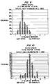
- Figure 7 is a graphical representation of the test results in the form of a bar graph. There are two bars at each length increment; one is for weight percent of the particles, and the second is number percent showing a distribution of the ungraded stripped catalyst. As shown there is some material below 1.5 millimeters and a large amount of material above 3.5 millimeters. Using the length grading method of the present invention selective cuts were made at 1.5 millimeters and 3.5 millimeters. The desired short fraction should have 1.5 millimeters and shorter material only, and the long fraction 3.5 millimeters and longer materials only, with a center cut only ranging from 1.5 millimeters to 3.5 millimeters.
- Figure 8 shows an attempt to isolate short material in a stripped catalyst, i.e., a less than 1.5 millimeters fraction and 15.9% on a volume basis was isolated from the total starting material. As seen in Figure 8, the preponderance of particles are in the 1.5 millimeters to shorter particle size range. There is approximately 10-15% of materials longer than 1.5 millimeters, and compared to the starting material, this represents a very dramatic improvement. The small materials have been isolated and nearly all of the materials longer than 1.5 millimeters have been eliminated or rejected.
- Figure 12 shows an attempt to remove just the small materials, i.e., 1.5 millimeters and shorter. There is more of a tail than there was with the stripped catalyst because of the biased distribution of the starting material. However, as seen in Figure 12 approximately 80% of the resulting particles were in the particle length range desired which shows a very high degree of selectivity that could never be approached by conventional screen techniques.
- Figure 13 shows the middle fraction and there is approximately 5%, or about 3% on a weight basis, of materials shorter than 1.5 millimeters and literally nothing longer than the 3.5 millimeters target range.
- Figure 14 shows the results of a very difficult separation because only about 7% of the material was being separated. In this case a significant amount of materials shorter than 3.5 millimeters results, but considering the starting distribution, the present process was extremely selective in pulling out just the longer materials with the minimum amount of shorter materials coming with it. In this connection, as seen in Figure 11, there is only about 4-6% of material in the 3.5 millimeters and above range and that would be an exceedingly difficult cut to isolate considering the small amount of material. But comparing this to Figure 14 the particle length distribution has been dramatically shifted and the average length has shifted from 1.55 to 2.82.
- the cut points used in these examples represent L/D ratios greater than 1.0.
- a high degree of separation and selectivity has been obtained in a single pass through the length grading equipment. Passing each of the various concentrated fractions (i.e., less than 1.5 millimeters, 1.5-3.5 millimeters, and greater than 3.5 millimeters) back through the length grading apparatus significantly improves the selectivity by further eliminating particles outside the desired particle length range. Such recycle or series operation is used in applications where extremely high selectivity is required.
- Figure 15 shows the distribution for a stripped material used in an experiment to make a cut at 2.5 millimeters. As seen from Figure 15, at about the 2.5 millimeters point, approximately 2/3 of the material should be 2.5 millimeters or shorter, and approximately 1/3 would be 2.5 millimeters or longer, and that is the split which was attempted.
- Figure 17 shows the distribution for particles above 2.5 millimeters and reveals almost no particles shorter than the target range of less than 2.5 millimeters.
Landscapes
- Chemical & Material Sciences (AREA)
- Engineering & Computer Science (AREA)
- Chemical Kinetics & Catalysis (AREA)
- Organic Chemistry (AREA)
- Oil, Petroleum & Natural Gas (AREA)
- Materials Engineering (AREA)
- General Chemical & Material Sciences (AREA)
- Catalysts (AREA)
- Combined Means For Separation Of Solids (AREA)
- Production Of Liquid Hydrocarbon Mixture For Refining Petroleum (AREA)
Abstract
Description
- The invention relates to the separation and isolation of shaped catalyst-type particles by length. More particularly, this invention relates to length grading of generally cylindrically-shaped catalyst-type particles, and to the regeneration, rejuvenation, and manufacture of catalyst-type particles which have been subjected to length grading.
- Catalysts used in the conversion and refining of hydrocarbons, as well as desorbents or adsorbents in the hydrocarbon separation or purification industry have a desired particle length requirement.
- Fresh, or virgin catalysts, desorbents and adsorbents require segmentation into a particular particle length category in order to achieve optimum packing or reduce fixed bed pressure drop, or in the case of fluid beds achieve optimum pumping requirements.
- In addition, catalysts used in the conversion and refining of hydrocarbons become contaminated with carbonaceous deposits, known as "coke", as well as metallic deposits, such as nickel, vanadium, iron or silica which may be present in the hydrocarbon feed as organometallic compounds or as tramp impurities. The spent catalyst becomes inactive and must be withdrawn from the catalyst reactor, and passed to a regenerator where coke is burned off to regenerate the catalyst, which is returned for reuse in the reactor. In addition to contamination, continued use of the catalyst results in catalyst attrition, i.e., the generally cylindrical catalyst particles become reduced in length to an undesirable degree. The presence of such shortened catalyst particles in a fixed bed reactor causes plugging of the bed and undesirable pressure buildup resulting in reduced flow and eventual shutdown of the bed. Historically, the catalyst industry has utilized classical screening techniques to remove "dust" or "fines", i.e., very small broken or deformed catalyst particles, from the catalyst mass.
However, use of a screen with a square aperture is limited by the diameter of the generally cylindrical catalyst particle or "pill". If the aperture of the screen is larger than the cross-sectional diameter of the pill, the screen cannot separate the catalyst pills on the basis of length. Screening can only be used to separate pills having a length-to-diameter ratio (L/D) less than one from pills having an L/D equal to or greater than one. Thus, a 12 mesh screen (square or slotted) having a 1.7 millimeter opening, which is either square or rectangular, will allow a 1/16 inch (1.6mm) diameter cylindrically shaped catalyst particle through the opening, whether the catalyst is 2 millimeters or 10 millimeters in length, as long as the catalyst enters the opening on end. Accordingly, in practice, the use of screening techniques is limited to removal of catalyst dust or fines in which the catalyst L/D is less than one. - Unfortunately, catalyst particles having an L/D greater than one can still be too short for usage in the reactor. Most frequently it is the particles with an L/D in the range of 1.0 to 2.0 that are undesirable and cause problems necessitating disposal of the entire catalyst batch containing such particles. Not only is such disposal costly and wasteful, in view of the great expense of catalysts, including those containing noble metals and the like, but, in addition, such disposal results in pollution and toxic waste disposal problems since many such catalysts contain toxic metals, such as cobalt, nickel, and vanadium.
- The manufacturing process for shaped catalysts includes sizing and/or breaking procedures to produce a product of a desired particle length distribution. With the state of the art in screening and separation technology, it is frequently difficult if not impossible to obtain the desired particle length distribution, or if it is achieved, this commonly results in the rejection of desired particles along with those undesired because of the poor selectivity of the equipment or process. Major improvements can be obtained if particles can be selectively separated on a length basis if the length division point is such that the L/D ratio is greater than one.
- Additionally, spent catalyst particle mixtures are "heterogeneous" in nature since the degree of feedstock-supplied metal contamination on each particle varies within the batch. Thus, a given batch of spent catalyst contains good catalyst particles and contaminated catalyst particles in varying degrees. However, since adequate methods are unavailable to separate the good particles from the more contaminated particles, the entire batch is often discarded.
- In other cases a given lot of catalyst may consist of two or more similarly shaped and sized particles but different in composition and individual pellet density. This may commonly be, for example, mixtures of hydrotreating and hydrocracking catalysts or nickel-molybdenum and cobalt-molybdenum catalysts. Such mixtures may be spent catalyst removed from a processing reactor or fresh catalyst which may have been inadvertently mixed during the manufacture or a handling process. These mixtures have diminished value and are commonly discarded.
- The "Gravity Separator Operating Instruction Manual" issued by Oliver Manufacturing Company, Inc. describes a gravity separator for separating particles of a similar size that differ in weight. However, such an apparatus is not suitable to separate efficiently particles differing in specific gravities and also in size, e.g. in length. According to the Introduction of said manual the gravity separator should not be used as a sizing machine.
- An apparatus for the selection of seeds or similar material is described in US-A-2 669 353. Such material, e.g. seed-grain, consists of particles which are irregular in shape, especially not generally cylindrical and do not necessarily have substantially the same cross-section diameter. The apparatus in said U.S.-patent does not present any feature which would enable the apparatus to select a group of particles of substantially the same diameter having a certain range of length from another group of particles which differ only in the range of length from that first group. The known apparatus can only achieve a size separation when the sizes are significantly different but not an effective length separation of a high degree of selectivity.
- In accordance with one aspect of the present invention an admixture consisting essentially of shaped, generally cylindrical, free flowing, similar, catalyst-type particles all having substantially the same diameter, are separated into a first group of particles having a length to diameter ratio (L/D) greater than one and a length below a predetermined length, L₁, in the range of from about 0.8 to about 24 millimeters, and a second group of particles having an L/D greater than one and a length above the predetermined length L₁, by passing the catalyst admixture into a cylindrical drum having inwardly opening indentations in a cylindrical wall thereof, the indentations having a transverse diameter approximately equal to L₁; rotating the drum about a longitudinal axis thereof at a speed sufficient to entrap particles in the indentations and convey the particles of the first group upwardly to a height permitting the particles to fall into a fixed, upwardly opening trough, while retaining the particles of the second group in a bottom portion of the drum; conveying the particles in the trough out a first outlet; and conveying the particles in the bottom of the drum out a second outlet, separate from the first outlet. As will be hereinafter demonstrated, the length grading process of the present invention is capable of providing a particle size selectivity previously unobtainable with catalyst-type particles.
- According to another aspect of the present invention, spent catalyst particles are deoiled, length graded and regenerated to remove carbonaceous deposits.
- According to still another aspect of the present invention, spent catalyst particles are regenerated and then length graded.
- According to further embodiment of the invention, spent catalyst is deoiled, extracted with acid to remove metal contaminants, regenerated to remove carbon contaminants, and then length graded.
- According to another aspect of the present invention similar or dissimilar, fresh, virgin, shaped catalyst, adsorbents, or desorbents, are length graded to achieve homogeneous length fractions.
- As will be hereinafter demonstrated, spent catalyst particles can be length graded within a very narrow particle distribution range with a precision unobtainable by conventional screen techniques.
-
- FIGS. 1 and 2 illustrate traditional screening techniques in accordance with the prior art;
- FIG.3 is a schematic diagram showing the process of the present invention;
- FIG.4 illustrates the length grading process of the present invention;
- FIG. 5 illustrates a side elevational view of a cylindrical catalyst particle of the present invention;
- FIG. 6 illustrates a partial perspective view of the length grading system of FIG. 4;
- FIGS. 7 - 17 graphically illustrate the high degree of selectivity achievable with the length grading method of the invention.
- The limitations of a prior art slotted or rectangular screen are illustrated in FIG. 1 where the light pellets A have a diameter less than the narrow opening of the slotted screen. The dark pills B have a diameter greater than the narrow opening of the slotted screen. As can be seen from FIG. 1, any pill with a dimension less than the narrow opening can pass through. Thus, in this case, all light pills (with a diameter less than the narrow opening) or all dark pills with a length less than the narrow opening can pass through. FIG. 1 shows that the slotted screen separation is based on a particle's smallest dimension, whereas in length grading in accordance with the present invention, separation is based upon a particle's greatest dimension.
- Another screening technique used to separate catalyst pills on a length basis employs vibrating "punched plates" as illustrated in FIG. 2 in accordance with the prior art. In this instance pills are axially aligned in the direction of movement and slide over the holes, and those pills with a length less than two times the hole diameter will "tip" over and pass through. The hole diameter must be greater than the pellet diameter so that this technique can only be used to separate at an L/D ratio greater than two. In practice this technique gives poor selectivity since the vibration of the apparatus required to move the pills across the plate causes many pills to bounce and simply fall through endwise, a problem similar to that experienced with square screens.
- Referring now to FIG. 3 of the drawings which is in accordance with the present invention, fresh catalyst particles all having substantially the same diameter are supplied by means of
lines 10 and 11 along with a hydrocarbon feedstock inline 12 toreactor 14 shown in block diagram form. The shaped catalyst-type particles of the present invention have a regular geometric shape, and are formed by extrusion or pelletizing. The catalyzed particles preferably have a generally cylindrical shape with a generally circular or polylobate cross section. The shaped catalyst-type particles of the present invention are to be distinguished from granular shaped particles which have an irregular shape. The preferred shaped catalyst particles treated by the process of the present invention have a cross-sectional diameter of from about 0.025 to about 1.0 inch (0.635 to about 25.4 mm), preferably from about 0.7 to about 4.0 mm. The diameter referred to in connection with the particles of the present invention is the largest cross-sectional diameter. The expression "substantially the same diameter" as used in the present application means that the diameter of a group of particles to be separated does not vary more than 10 percent. - The process of the present invention is suitable for treatment of any "catalyst-type particle". As used in the present application, the term "catalyst-type particle" means catalysts, catalyst supports, and sorbents. The term "similar" catalyst-type particles means substantially, all of said particles in the mixture have substantially the same chemical composition, e.g., cobalt molybdate on alumina. The term "dissimilar" catalyst-type particle mixture means the mixture contains a significant portion of particles of more than one type, e.g., a mixture comprising cobalt molybdate on alumina particles and alumina per se particles. The catalyst-type particles treated in accordance with the present invention may comprise any of the conventional catalysts used in conversion or refining of hydrocarbons, such as hydrotreating catalysts which commonly contain active metals from the group cobalt, molybdenum, nickel, tungsten and titanium supported on shaped alumina or silica alumina; hydrocracking catalysts which commonly contain active metals such as nickel, molybdenum, tungsten, and palladium supported on shaped silica-alumina or molecular sieves; reforming catalysts which commonly contain platinum, palladium or platinum in combination with another transition or rare earth metal supported on shaped alumina. Catalyst supports or sorbents, for example, silica, alumina, silica-alumina or molecular sieves without promoter metals may also be treated in accordance with this invention. For the purposes of illustration the following description will be directed to nickel-molybdate on a refractory metal oxide support.
- The hydrocarbon feedstock from
line 12 is subjected to hydrotreating, for example, inreactor 14 under conventional hydrotreating conditions, and the hydrocarbon products are withdrawn fromreactor 14 by means ofline 16.Reactor 14 can be a fixed bed, ebullated bed, slurry or fluidized bed type of reactor. Under continued usage the catalyst is subject to attrition, and carbonaceous deposits accumulate on the catalyst. Also, metallic deposits from the hydrocarbon feedstock, such as nickel, vanadium, iron and silica deposit on the catalyst particles. Such attrition and fouling reduces the effectiveness of the catalyst mass and if permitted to continue will result in the shutdown ofreactor 14. Thus, spent catalyst particles are withdrawn fromreactor 14 by means oflines stripper 20 where the spent catalyst particles are deoiled so as to render them free flowing. Instripper 20 the oily spent catalyst particles may be contacted with an inert gas, such as nitrogen, introduced by means ofline 22, while being heated to a temperature of from about 100° to about 500°C, to volatize aqueous or oily residue on the spent catalyst particles. Volatized hydrocarbon or water is withdrawn fromstripper 20 by means ofline 24. Alternatively, the spent catalyst particles can be stripped inreactor 14 to remove hydrocarbons and thereby eliminate the need forstripper 20. In that event the free flowing particles are passed directly to length grading or regeneration hereinafter described (by means not shown). - Free flowing catalyst particles are withdrawn from
stripper 20 by means ofline 26 and passed by means ofline 28 tolength grading zone 30. - Referring now to FIG. 4, the length grading zone of the present invention is shown in more detail.
- The separation zone comprises
length separator apparatus 100 in which particles P (see FIG. 5) are to be separated according to their length, including the separation of two sets of particles, the first set comprising particles of length less than L₁ (the cut point) and a second set comprising particles of length greater than L₁, such that L₁ is greater than the transverse cross-sectional diameter D. The particles in both sets have substantially the same diameter and an L/D greater than one. Preferably, the particles in the first set have an L/D greater than one, but less than 2.0. Thus, the preferred particles to be isolated are the longer second set particles having a minimum length such that the L/D of such particles is between 1.0 and 2.0. - Preferably, selectivity of the process is at least 80-90 percent on a single pass through the length grading zone. Selectivity is defined as the percent removal of undesireable particles. In other words, in a given application of the process to a batch of particles, at least 80-90 percent of the particles with a length less than L₁ would be separated from the desired particles, which have a length greater than L₁, leaving no more than 10-20 percent of the original undersized particles in the desired fraction, e.g., the second set. The apparatus includes a
cylindrical wall 102 having a plurality of inwardly opening, outwardly extendingindentations 104. The cylindrical wall is rotatably mounted in a frame for rotation about its longitudinal axis. The indentations are hemispherical in shape and have a transverse diameter at the inner surface ofcylindrical wall 102 equal to the minimal acceptable length, L₁, for the catalyst particles. L₁ is in the range of 0.8 to about 24 millimeters, preferably in the range of from about 0.8 to about 6 millimeters. - A U-shaped trough-
like member 106 is fixedly mounted withincylindrical wall 102 such that the cylindrical wall rotates independently of the trough member and about the stationary trough member.Member 106 compriseslegs Legs conveyer 112 is rotatably mounted withintrough member 106. However, the material intrough member 106 may be conveyed by vibrating motion also. This conveyer moves particles placed within the trough along the length of the trough and out a discharge end thereof. - In operation, the catalyst particles to be separated are fed into the interior of
cylindrical wall 102 such that they rest on a lower portion thereof. The cylindrical wall is then rotated about its longitudinal axis in the direction indicated by arrow 114. As the cylindrical wall is rotated, the particles having a length L less than the opening diameter d ofindentation 104 become lodged withinhemispherical indentations 104. These particles are then lifted by a combination of the centrifugal forces applied to these particles, their entrapment within the hemispherical indentations and the rotation ofcylindrical wall 102 to a point above the free end ofleg 108 oftrough member 106. At a point betweenlegs trough member 106. - The particles which are too long, i.e., having a length L greater than the diameter d of
indentations 104, cannot enter or become entrapped within the indentations. This will cause such particles to slip along the inside surface ofcylindrical wall 102, and not be raised about the free end ofleg 108. These longer particles remain outside oftrough member 106. - In this manner, the set of relatively shorter particles is removed from the set or relatively longer particles placed in
cylindrical wall 102, by the shorter set being deposited withintrough member 106 and conveyed out oftrough 106 byconveyer 112. The longer particles remain at the bottom ofcylindrical wall 102. The relatively shorter particles having a length sufficiently small to fit within the indentations remain intermixed with the longer particles within the cylindrical wall until the shorter particles filter down and are entrapped within the indentations. The particles are subjected to rotation within the cylindrical wall for a time period sufficient to remove essentially all of the undesirable shorter particles having a length L less than the diameter d of the hemispherical indentations. - The separation of the particles is not limited by the ratio L/D of the particles. The desired separation or the minimum acceptable length for the particles can be set by choosing the diameter d of the
hemispherical indentations 104. - After essentially all of the undesired, too short particles have been removed by being deposited within
trough member 106, the remaining particles lying in the bottom ofcylindrical wall 102 can be removed from the cylindrical wall for further processing or use. The desired longer particles can be recycled tounit 30 to provide an even greater degree of selectivity and further remove small quantities of undesired, shorter particles. Apparatus which can be adapted for use in the method of the present invention is shown in US-A-2 119 997. - Referring again to FIG. 3, length graded catalyst particles having the desired L/D greater than one are withdrawn from
length grading zone 30 by means ofline 32 and passed by means oflines 33 and 34 toregeneration zone 36 for removal of the carbonaceous deposits from the length graded catalyst particles.Regeneration zone 36 may be a conventional regenerator in which an oxygen-containing gas is supplied by means ofline 38 under combustion conditions to oxidize the carbonaceous deposits to carbon dioxide which is withdrawn byline 40. Suitable oxidation temperatures include from about 200° to about 700°C, preferably from about 350° to about 500°C under atmospheric pressure. - The length graded, regenerated catalyst is withdrawn from
regeneration zone 36 by means ofline 42 and passed by means ofline 44 to join fresh catalyst fromline 10 for passage toreactor 14 by means of line 11. - It is desirable to remove volatile hydrocarbons in
stripper 20 prior to regeneration inzone 36, since the oxidative regeneration process is exothermic, and the presence of the hydrocarbons during oxidation makes regeneration more difficult to control. Likewise, removal of the volatile hydrocarbons is desirable prior to length grading to avoid agglomeration of the catalyst particles which renders them more difficult to separate. - If the spent catalyst withdrawn from
reactor 14 contains a high percentage (25-75 percent) of particles having an L/D greater than one with an undesirably short length, it is preferred to use length grading prior to regeneration to reduce the quantity of particles regenerated and thus reduce the cost of regeneration. However, if the quantity of undesirable particles is relatively small, then the spent catalyst fromreactor 14 may be passed by means oflines regeneration zone 36 or, alternatively if the catalyst is oil wet, the catalyst may be passed fromreactor 14 tostripper 20 bylines regeneration 36 bylines lines length grading zone 30 for length grading. Thereafter, the regenerated, length graded particles may be returned by means oflines reactor 14. - If the spent catalyst particles withdrawn from
reactor 14 are heavily laden with foreign or tramp metals, such as nickel and vanadium, picked up from the hydrocarbon feedstock, the spent catalyst fromline 18 is passed by means ofline 19 to strippingzone 20 to be de-oiled, as before, and then passed by means oflines extraction zone 56 in which a portion of the undesired metals are selectively acid leached from the catalyst particles. The leaching operation consists of contacting the catalyst particles with an aqueous solution containing 2-20 weight percent sulfuric, sulfonic, nitric, acetic or citric acids at an elevated temperature, preferably 60°-250°F (16-121°C), for a period in excess of five minutes. The acid soaked catalyst pellets are typically rinsed with water before being passed on for further treatment. A process which can be adopted for use in the method of the present invention is described in US-A-4 454 240. - The nickel and vanadium reduced catalyst particles are withdrawn from
extraction zone 56 by means ofline 58 and passed byline regeneration zone 36 for removal of carbonaceous deposits as previously described. The rejuvenated and regenerated catalyst is passed bylines length grading zone 30, and then recycled by means oflines reactor 14. - In accordance with a preferred embodiment of the present invention, spent catalyst from
reactor 14, which is laden with heavy metals, such as nickel and vanadium, is passed by means oflines zone 20, and the resulting free flowing deoiled catalyst particles are then passed by means oflines length grading zone 30. Free-flowing particles having the desired length are passed by means oflines density grading zone 64 for density grading. - A preferred density grading system is described in a divisional European patent application.
- In density grading zone 64 a light catalyst fraction is produced, which contains little or no heavy metal contamination, and this light fraction is passed by means of
lines regeneration zone 36 to remove carbonaceous deposits. The substantially carbon-free, light catalyst fraction can be recycled by means oflines reactor 14. Alternatively, if the metals contaminates of the light fraction are too high to allow direct re-use through regeneration, they may be passed through theextraction zone 56 andregeneration zone 36 as described for the medium density fraction below. - A medium density catalyst fraction is withdrawn from
density grading zone 64 by means ofline 67 and passed by means oflines extraction zone 56 for removal of heavy metals. Thereafter the rejuvenated catalyst fraction may be passed by means oflines regeneration zone 36 for removal of carbon. The catalyst particles are then returned toreactor 14 by means oflines - A heavily contaminated fraction is withdrawn from
density grading zone 64 by means ofline 72, and this fraction can be sent to disposal by means ofline 73 or can be passed by means oflines - In accordance with another embodiment of the present invention, spent catalyst from
reactor 14 is passed by means oflines stripper 20 to provide free flowing particles which are withdrawn by means ofline 26 and passed bylines regenerator 36. Regenerated particles are withdrawn by means ofline 42 and passed bylines unit 30 for removal of the undesired shorter particles which are sent to disposal by means ofline 31. The desired, longer particles are passed by means oflines unit 64 to produce three fractions, namely, a light density catalyst fraction, which contains little or no heavy metal contamination, a medium density catalyst fraction, which is lightly contaminated with metal impurities, and a heavily metals-contaminated fraction. The light friction can be recycled directly toreactor 14 by means oflines extractor 56 by means oflines lines extractor 56, while the heavy fraction can be passed by means ofline extractor 56, or can be passed to disposal by means ofline 73. - From the foregoing it can be seen that in complicating circumstances a combination of length grading and density grading is particularly advantageous and leads to reusable catalyst-type particles.
- The following example demonstrates the high degree of length grading selectivity achievable by the length grading techniques of the present invention.
- In order to demonstrate the high degree of selectivity available by the method of the present invention, two experiments were conducted with spent catalyst which had been stripped and a second sample which had been regenerated. The catalyst used in these examples has a diameter of 0.9 millimeter. The catalyst must be oil-free or regenerated before processing because it must be free flowing before subjected to length grading. Each catalyst sample was divided into three fractions on the basis of length using the apparatus depicted in Figure 4 of the drawings. The results are set forth in Table 1, below:
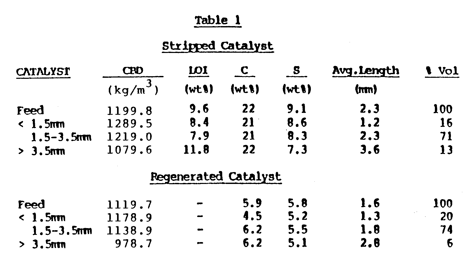
- As seen in Table 1, the stripped catalyst feed material has a density of about 1199.8 kilogram/ cubic meter and an average length of 2.3 millimeters. The tests were conducted to first remove a fraction of catalyst with a length of 1.5 millimeters or shorter; the fraction with a length greater than 1.5 millimeters was then divided into a fraction in the range of 1.5-3.5 millimeters and a fraction with a length greater than 3.5 millimeters. As seen under the stripped catalyst section at the top of Table 1, three distinct fractions resulted; a short fraction having an average length of 1.2 millimeters, a medium sized fraction of 2.3 millimeters, and a third fraction with an average length of 3.6 millimeters. As seen in the last column of Table 1, the volume distribution achieved was 16% short, 71% medium length, and 13% long. This is a reflection of the amount of catalyst on a fresh basis that is divided into the three fractions.
- Similar data was achieved for the regenerated catalyst. The regenerated catalyst has a somewhat shorter average length, (1.6 millimeters vs. 2.3 millimeters) for the feed materials. However, it is seen that there is a distinct difference in the three fractions. The short having an average length of 1.3 millimeters, the medium material has an average length of 1.8 millimeters, and finally, the long material has an average length of 2.8 millimeters. The volume breakdown of the distribution for the three fractions shows that the regenerated catalyst can be cut into three significantly different fractions on the basis of average length.
- Figure 7 is a graphical representation of the test results in the form of a bar graph. There are two bars at each length increment; one is for weight percent of the particles, and the second is number percent showing a distribution of the ungraded stripped catalyst. As shown there is some material below 1.5 millimeters and a large amount of material above 3.5 millimeters. Using the length grading method of the present invention selective cuts were made at 1.5 millimeters and 3.5 millimeters. The desired short fraction should have 1.5 millimeters and shorter material only, and the long fraction 3.5 millimeters and longer materials only, with a center cut only ranging from 1.5 millimeters to 3.5 millimeters.
- Figure 8 shows an attempt to isolate short material in a stripped catalyst, i.e., a less than 1.5 millimeters fraction and 15.9% on a volume basis was isolated from the total starting material. As seen in Figure 8, the preponderance of particles are in the 1.5 millimeters to shorter particle size range. There is approximately 10-15% of materials longer than 1.5 millimeters, and compared to the starting material, this represents a very dramatic improvement. The small materials have been isolated and nearly all of the materials longer than 1.5 millimeters have been eliminated or rejected.
- Referring to Figure 9, it is seen that 71.2% by volume of the middle fraction, 1.5-3.5 millimeters, has been isolated with about 5% of the material that lies outside the range of 1.5-3.5 millimeters. Thus, a very narrow distribution of particles falling 95%+ within the designated particle length range was achieved.
- Referring to Figure 10, it is seen that 12.9% has gone into a long fraction. As seen in Figure 10, there is probably 10-12% of material shorter than 3.5 millimeters, but the tail or long materials have been isolated from the initial starting material.
- Referring to Figure 11, the distribution of regenerated catalysts that were to be length graded is shown. By comparison to the stripped material, it is quite a bit shorter, the distribution is biased much more to the short end than was the stripped material. However, the present length grading process is unaffected to a large extent by the distribution.
- Figure 12 shows an attempt to remove just the small materials, i.e., 1.5 millimeters and shorter. There is more of a tail than there was with the stripped catalyst because of the biased distribution of the starting material. However, as seen in Figure 12 approximately 80% of the resulting particles were in the particle length range desired which shows a very high degree of selectivity that could never be approached by conventional screen techniques.
- Figure 13 shows the middle fraction and there is approximately 5%, or about 3% on a weight basis, of materials shorter than 1.5 millimeters and literally nothing longer than the 3.5 millimeters target range.
- Figure 14 shows the results of a very difficult separation because only about 7% of the material was being separated. In this case a significant amount of materials shorter than 3.5 millimeters results, but considering the starting distribution, the present process was extremely selective in pulling out just the longer materials with the minimum amount of shorter materials coming with it. In this connection, as seen in Figure 11, there is only about 4-6% of material in the 3.5 millimeters and above range and that would be an exceedingly difficult cut to isolate considering the small amount of material. But comparing this to Figure 14 the particle length distribution has been dramatically shifted and the average length has shifted from 1.55 to 2.82.
- It is important that the cut points used in these examples represent L/D ratios greater than 1.0. In the first cut the L/D ratio is 1.5/0.9 = 1.67; and the second cut has an L/D ratio of 3.5/0.9 = 3.89. Further, it should be understood that a high degree of separation and selectivity has been obtained in a single pass through the length grading equipment. Passing each of the various concentrated fractions (i.e., less than 1.5 millimeters, 1.5-3.5 millimeters, and greater than 3.5 millimeters) back through the length grading apparatus significantly improves the selectivity by further eliminating particles outside the desired particle length range. Such recycle or series operation is used in applications where extremely high selectivity is required.
- Figure 15 shows the distribution for a stripped material used in an experiment to make a cut at 2.5 millimeters. As seen from Figure 15, at about the 2.5 millimeters point, approximately 2/3 of the material should be 2.5 millimeters or shorter, and approximately 1/3 would be 2.5 millimeters or longer, and that is the split which was attempted.
- As seen in Figure 16, the length distribution of the material shorter than 2.5 millimeters is depicted and 62% on a volume basis has been isolated. Surprisingly, less than 5%, i.e., 2-3% of the material is outside the target range of less than 2.5 millimeters.
- Figure 17 shows the distribution for particles above 2.5 millimeters and reveals almost no particles shorter than the target range of less than 2.5 millimeters.
Claims (10)
- A process for treating a mixture of free flowing catalyst-type particles (catalysts, catalyst supports and sorbents) consisting essentially of a regular geometric shape, particularly of a generally cylindrical shape, having substantially the same diameter, varying length and an L/D greater than one, a first group of them having a length below a predetermined length, L₁, said length, L₁, being in the range of from 0.8 to about 24 mm, and a second group of particles having a length greater than L₁, comprising the steps of:a) feeding said mixture of catalyst-type particles into a length grading zone comprising a rotating cylindrical drum having inwardly opening indentations in a cylindrical wall thereof, the indentations having a transverse diameter L₁;b) rotating the drum about a longitudinal axis thereof at a speed sufficient to entrap in the indentations and convey the particles having a length below L₁ upwardly to a height permitting the particles to fall into a fixed, upwardly opening trough, while the particles having a length above L₁ remain outside of the trough in a bottom portion of said drum;c) conveying said particles in the trough out a first outlet; andd) conveying said particles in the bottom portion of the drum out a second outlet, separate from said first outlet, and recovering said particles having a length above L₁ for further processing or use.
- A process as defined in claim 1 wherein said second group of particles comprise particles having an L/D between 1.0 and 2.0.
- A process as defined in claim 1 wherein said particles have been rendered free flowing by treatment with an inert stripping gas while heating.
- A process as defined in claim 1 wherein said particles contain active catalytic metals from the group of cobalt, nickel, molybdenum, titanium or tungsten on a refractory metal oxide support.
- A process as defined in claim 1 wherein said particles are pelletized or extruded alumina, silica-alumina, silica, molecular sieves or combinations thereof.
- A process as defined in claim 1 where L₁ is in the range of from 0.8 to about 6 mm.
- A process as defined in any one of claims 1 to 6 wherein said particles consist of a spent catalyst-type particle mixture which prior to passing to the length grading zone is passed to a stripping zone to remove volatizable hydrocarbons from said catalyst-type particles and to a regeneration zone to remove carbon deposits from the surface of said catalyst particles and to provide regenerated catalyst-type particles.
- A process as defined in claim 7 wherein said stripped catalyst-type particles are contacted with a leaching acid to remove heavy metals.
- A process as defined in claim 7 wherein said regenerated catalyst-type particles are contacted with a leaching acid to remove heavy metals.
- A process as defined in any one of claims 1 to 6, wherein said particles consist of a spent catalyst-type particle mixture which prior to passing to the length grading zone is passed to a regeneration zone to remove carbon deposits from the surface of the particles.
Priority Applications (1)
| Application Number | Priority Date | Filing Date | Title |
|---|---|---|---|
| EP91122362A EP0479343B1 (en) | 1986-03-10 | 1987-03-09 | Production of improved catalyst-type particles using density grading |
Applications Claiming Priority (2)
| Application Number | Priority Date | Filing Date | Title |
|---|---|---|---|
| US83769086A | 1986-03-10 | 1986-03-10 | |
| US837690 | 1986-03-10 |
Related Child Applications (1)
| Application Number | Title | Priority Date | Filing Date |
|---|---|---|---|
| EP91122362.6 Division-Into | 1991-12-30 |
Publications (3)
| Publication Number | Publication Date |
|---|---|
| EP0274479A1 EP0274479A1 (en) | 1988-07-20 |
| EP0274479A4 EP0274479A4 (en) | 1990-01-08 |
| EP0274479B1 true EP0274479B1 (en) | 1993-07-14 |
Family
ID=25275146
Family Applications (2)
| Application Number | Title | Priority Date | Filing Date |
|---|---|---|---|
| EP19870902239 Expired - Lifetime EP0274479B1 (en) | 1986-03-10 | 1987-03-09 | Process for the separation and isolation of shaped catalyst-type particles by length |
| EP91122362A Expired - Lifetime EP0479343B1 (en) | 1986-03-10 | 1987-03-09 | Production of improved catalyst-type particles using density grading |
Family Applications After (1)
| Application Number | Title | Priority Date | Filing Date |
|---|---|---|---|
| EP91122362A Expired - Lifetime EP0479343B1 (en) | 1986-03-10 | 1987-03-09 | Production of improved catalyst-type particles using density grading |
Country Status (6)
| Country | Link |
|---|---|
| EP (2) | EP0274479B1 (en) |
| JP (2) | JP2592877B2 (en) |
| AU (1) | AU7205287A (en) |
| CA (1) | CA1294943C (en) |
| DE (2) | DE3786544T2 (en) |
| WO (1) | WO1987005232A1 (en) |
Families Citing this family (8)
| Publication number | Priority date | Publication date | Assignee | Title |
|---|---|---|---|---|
| US5209840A (en) * | 1991-10-02 | 1993-05-11 | Texaco Inc. | Separation of active catalyst particles from spent catalyst particles by air elutriation |
| FR2782936B1 (en) * | 1998-09-09 | 2000-10-27 | Inst Francais Du Petrole | DEVICE AND METHOD FOR SORTING SOLID PARTICLES BY DENSITY CLASS |
| WO2001094009A1 (en) | 2000-06-08 | 2001-12-13 | Japan Energy Corporation | Method for preparing catalyst for use in hydro-refining and method for recovering metal |
| JP4604607B2 (en) * | 2003-08-22 | 2011-01-05 | 三菱化学株式会社 | Catalyst regeneration method |
| EP2340812A1 (en) | 2009-12-18 | 2011-07-06 | Ferring International Center S.A. | Granules for pharmaceutical preparations, methods and apparatus for their production |
| JP5803224B2 (en) * | 2011-04-06 | 2015-11-04 | 三菱レイヨン株式会社 | Vibrating sieve machine |
| SG11201403632XA (en) * | 2012-03-19 | 2014-09-26 | Mitsubishi Rayon Co | Pillared body separation method and pillared body separation device |
| JP6020686B2 (en) * | 2015-08-31 | 2016-11-02 | 三菱レイヨン株式会社 | Vibrating sieve machine |
Family Cites Families (7)
| Publication number | Priority date | Publication date | Assignee | Title |
|---|---|---|---|---|
| US2119997A (en) * | 1935-09-21 | 1938-06-07 | Richmond Mfg Company | Means for increasing the separating capacity of grain separating cylinders |
| US2494556A (en) * | 1946-07-13 | 1950-01-17 | Houdry Process Corp | Treating clay catalysts used for conversion of sulfur containing feeds |
| US2567207A (en) * | 1947-01-21 | 1951-09-11 | Houdry Process Corp | Maintenance of catalytic activity in hydrocarbon conversion systems |
| US2669353A (en) * | 1949-02-11 | 1954-02-16 | Heid Ag Maschf | Apparatus for the selection of seeds or similar material |
| US2759605A (en) * | 1951-11-29 | 1956-08-21 | Oliver W Steele | Gravity separator |
| US3702238A (en) * | 1970-03-18 | 1972-11-07 | Gulf Oil Corp | Apparatus for by-passing reactants to the interior of a catalyst bed |
| US4454240A (en) * | 1981-11-02 | 1984-06-12 | Hri, Inc. | Catalyst regeneration process including metal contaminants removal |
-
1987
- 1987-03-09 DE DE19873786544 patent/DE3786544T2/en not_active Expired - Fee Related
- 1987-03-09 AU AU72052/87A patent/AU7205287A/en not_active Abandoned
- 1987-03-09 DE DE19873752106 patent/DE3752106T2/en not_active Expired - Lifetime
- 1987-03-09 CA CA000531554A patent/CA1294943C/en not_active Expired - Lifetime
- 1987-03-09 WO PCT/US1987/000524 patent/WO1987005232A1/en not_active Ceased
- 1987-03-09 EP EP19870902239 patent/EP0274479B1/en not_active Expired - Lifetime
- 1987-03-09 JP JP62502088A patent/JP2592877B2/en not_active Expired - Lifetime
- 1987-03-09 EP EP91122362A patent/EP0479343B1/en not_active Expired - Lifetime
-
1996
- 1996-07-08 JP JP17773596A patent/JP2648588B2/en not_active Expired - Fee Related
Also Published As
| Publication number | Publication date |
|---|---|
| CA1294943C (en) | 1992-01-28 |
| JP2592877B2 (en) | 1997-03-19 |
| EP0274479A4 (en) | 1990-01-08 |
| EP0479343A2 (en) | 1992-04-08 |
| JPS63502648A (en) | 1988-10-06 |
| DE3752106T2 (en) | 1998-03-12 |
| JP2648588B2 (en) | 1997-09-03 |
| DE3752106D1 (en) | 1997-09-18 |
| AU7205287A (en) | 1987-09-28 |
| EP0479343B1 (en) | 1997-08-13 |
| WO1987005232A1 (en) | 1987-09-11 |
| JPH09949A (en) | 1997-01-07 |
| DE3786544T2 (en) | 1994-02-03 |
| EP0479343A3 (en) | 1992-09-23 |
| DE3786544D1 (en) | 1993-08-19 |
| EP0274479A1 (en) | 1988-07-20 |
Similar Documents
| Publication | Publication Date | Title |
|---|---|---|
| US4720473A (en) | Production of improved catalyst-type particles using length and density grading | |
| JPH05200313A (en) | Method for separating activated catalyst particle from used catalyst particle by winnowing | |
| EP2008726A1 (en) | Colour sorting of catalyst or adsorbent particles | |
| US20030130118A1 (en) | Method for manufacturing hydrorefining catalyst, and metal recovery method | |
| US5636747A (en) | Combination magnetic separation, classification and attrition process for renewing and recovering particulates | |
| JPH09173849A (en) | Method for preparing hydroprocessing catalysts from waste hydroprocessing catalysts | |
| CA1294943C (en) | Production of improved catalyst-type particles using length and density grading | |
| JPH07116524A (en) | Method for reactivation of waste catalyst for hydrogenation treatment carrying alumina | |
| US5082552A (en) | Hydrotreating with catalyst particles using length and density grading | |
| US5837637A (en) | Catalyst regeneration | |
| WO2005028374A2 (en) | Filtration method | |
| DE69604936T2 (en) | METHOD FOR REGENERATING CATALYSTS | |
| EP0420652A1 (en) | Slurry hydrotreating process | |
| US2892771A (en) | Removing contaminants from catalyst particles | |
| EP0555593B1 (en) | Process for hydrogenatively treating petroleum distillation residual oils | |
| EP0441111A1 (en) | Particulate material | |
| WO1987001303A1 (en) | Removal of inorganic contaminants from catalysts | |
| CA1159402A (en) | Segregating used catalyst fractions by liquid fluidization | |
| EP0888186B1 (en) | Process for preparing a large pore hydroprocessing catalyst | |
| DE19837957C1 (en) | Method and apparatus for control of dust in a fluid bed reactor | |
| DE2251514C3 (en) | Process for the expulsion of volatile substances from a catalyst | |
| KR102065798B1 (en) | Spent catalyst sorting apparatus for Residue Fluid Catalytic Cracking | |
| NL8204165A (en) | DEVICE FOR CLASSIFYING CATALYST PARTICLES AND CATALYTIC METHOD USING CATALYST PARTICLES CLASSIFIED WITH THE SAID DEVICE. | |
| JPH07246538A (en) | Chip discharging device | |
| GB2122638A (en) | Two-stage treatment process for shale oil containing shale solids and metals |
Legal Events
| Date | Code | Title | Description |
|---|---|---|---|
| PUAI | Public reference made under article 153(3) epc to a published international application that has entered the european phase |
Free format text: ORIGINAL CODE: 0009012 |
|
| 17P | Request for examination filed |
Effective date: 19880219 |
|
| AK | Designated contracting states |
Kind code of ref document: A1 Designated state(s): DE FR GB IT LU |
|
| A4 | Supplementary search report drawn up and despatched |
Effective date: 19900108 |
|
| 17Q | First examination report despatched |
Effective date: 19910322 |
|
| GRAA | (expected) grant |
Free format text: ORIGINAL CODE: 0009210 |
|
| AK | Designated contracting states |
Kind code of ref document: B1 Designated state(s): DE FR GB IT LU |
|
| REF | Corresponds to: |
Ref document number: 3786544 Country of ref document: DE Date of ref document: 19930819 |
|
| ITF | It: translation for a ep patent filed | ||
| ET | Fr: translation filed | ||
| EPTA | Lu: last paid annual fee | ||
| PLBE | No opposition filed within time limit |
Free format text: ORIGINAL CODE: 0009261 |
|
| STAA | Information on the status of an ep patent application or granted ep patent |
Free format text: STATUS: NO OPPOSITION FILED WITHIN TIME LIMIT |
|
| 26N | No opposition filed | ||
| REG | Reference to a national code |
Ref country code: GB Ref legal event code: IF02 |
|
| PGFP | Annual fee paid to national office [announced via postgrant information from national office to epo] |
Ref country code: GB Payment date: 20040309 Year of fee payment: 18 Ref country code: FR Payment date: 20040309 Year of fee payment: 18 |
|
| PGFP | Annual fee paid to national office [announced via postgrant information from national office to epo] |
Ref country code: LU Payment date: 20040330 Year of fee payment: 18 |
|
| PGFP | Annual fee paid to national office [announced via postgrant information from national office to epo] |
Ref country code: DE Payment date: 20040406 Year of fee payment: 18 |
|
| PG25 | Lapsed in a contracting state [announced via postgrant information from national office to epo] |
Ref country code: LU Free format text: LAPSE BECAUSE OF NON-PAYMENT OF DUE FEES Effective date: 20050309 Ref country code: IT Free format text: LAPSE BECAUSE OF NON-PAYMENT OF DUE FEES;WARNING: LAPSES OF ITALIAN PATENTS WITH EFFECTIVE DATE BEFORE 2007 MAY HAVE OCCURRED AT ANY TIME BEFORE 2007. THE CORRECT EFFECTIVE DATE MAY BE DIFFERENT FROM THE ONE RECORDED. Effective date: 20050309 Ref country code: GB Free format text: LAPSE BECAUSE OF NON-PAYMENT OF DUE FEES Effective date: 20050309 |
|
| PG25 | Lapsed in a contracting state [announced via postgrant information from national office to epo] |
Ref country code: DE Free format text: LAPSE BECAUSE OF NON-PAYMENT OF DUE FEES Effective date: 20051001 |
|
| GBPC | Gb: european patent ceased through non-payment of renewal fee |
Effective date: 20050309 |
|
| PG25 | Lapsed in a contracting state [announced via postgrant information from national office to epo] |
Ref country code: FR Free format text: LAPSE BECAUSE OF NON-PAYMENT OF DUE FEES Effective date: 20051130 |
|
| REG | Reference to a national code |
Ref country code: FR Ref legal event code: ST Effective date: 20051130 |