EP0274408B1 - Automatic thermal and speed controls for viscous fluid clutches - Google Patents
Automatic thermal and speed controls for viscous fluid clutches Download PDFInfo
- Publication number
- EP0274408B1 EP0274408B1 EP88300019A EP88300019A EP0274408B1 EP 0274408 B1 EP0274408 B1 EP 0274408B1 EP 88300019 A EP88300019 A EP 88300019A EP 88300019 A EP88300019 A EP 88300019A EP 0274408 B1 EP0274408 B1 EP 0274408B1
- Authority
- EP
- European Patent Office
- Prior art keywords
- fluid
- valve
- pressure
- reservoir
- clearance gap
- Prior art date
- Legal status (The legal status is an assumption and is not a legal conclusion. Google has not performed a legal analysis and makes no representation as to the accuracy of the status listed.)
- Expired - Lifetime
Links
Images


Classifications
-
- F—MECHANICAL ENGINEERING; LIGHTING; HEATING; WEAPONS; BLASTING
- F16—ENGINEERING ELEMENTS AND UNITS; GENERAL MEASURES FOR PRODUCING AND MAINTAINING EFFECTIVE FUNCTIONING OF MACHINES OR INSTALLATIONS; THERMAL INSULATION IN GENERAL
- F16D—COUPLINGS FOR TRANSMITTING ROTATION; CLUTCHES; BRAKES
- F16D35/00—Fluid clutches in which the clutching is predominantly obtained by fluid adhesion
- F16D35/02—Fluid clutches in which the clutching is predominantly obtained by fluid adhesion with rotary working chambers and rotary reservoirs, e.g. in one coupling part
- F16D35/021—Fluid clutches in which the clutching is predominantly obtained by fluid adhesion with rotary working chambers and rotary reservoirs, e.g. in one coupling part actuated by valves
- F16D35/026—Fluid clutches in which the clutching is predominantly obtained by fluid adhesion with rotary working chambers and rotary reservoirs, e.g. in one coupling part actuated by valves actuated by a plurality of valves; the valves being actuated by a combination of mechanisms covered by more than one of groups F16D35/022 - F16D35/025
-
- G—PHYSICS
- G05—CONTROLLING; REGULATING
- G05D—SYSTEMS FOR CONTROLLING OR REGULATING NON-ELECTRIC VARIABLES
- G05D16/00—Control of fluid pressure
- G05D16/04—Control of fluid pressure without auxiliary power
- G05D16/10—Control of fluid pressure without auxiliary power the sensing element being a piston or plunger
-
- G—PHYSICS
- G05—CONTROLLING; REGULATING
- G05D—SYSTEMS FOR CONTROLLING OR REGULATING NON-ELECTRIC VARIABLES
- G05D23/00—Control of temperature
- G05D23/01—Control of temperature without auxiliary power
- G05D23/02—Control of temperature without auxiliary power with sensing element expanding and contracting in response to changes of temperature
- G05D23/021—Control of temperature without auxiliary power with sensing element expanding and contracting in response to changes of temperature the sensing element being a non-metallic solid, e.g. elastomer, paste
- G05D23/023—Control of temperature without auxiliary power with sensing element expanding and contracting in response to changes of temperature the sensing element being a non-metallic solid, e.g. elastomer, paste the sensing element being placed outside a regulating fluid flow
Definitions
- This invention relates to automatic controls for viscous fluid clutches and is particularly though not exclusively applicable to controls for viscous fluid clutches incorporated in drives to cooling fans for vehicle engines. It is well-known that for optimum efficiency the speed of the fan needs to be controlled in response to a number of operating parameters, primarily the sensed temperature of a component of the engine, for which purpose it is normal to sense the temperature of the coolant liquid or a cooling air stream. Many systems already exist for controlling a clutch or other coupling between an engine and an associated cooling fan to vary the speed of the fan in accordance with a sensed temperature with the object of maintaining engine temperature approximately within a predetermined range.
- German published Patent Specification DE-A-3 204 554 discloses a viscous fluid clutch including a valve controlling flow from a reservoir to a clearance gap, the valve having a moveable control element moved between a fully open and a fully closed position by a pressure force from a thermal sensor.
- the invention is particularly applicable to controls for viscous fluid clutches of the type having means for controlling the torsional drive through the clutch by transferring fluid from the clearance gap of the clutch to a reservoir and allowing controlled quantities of fluid to return from the reservoir to the clearance gap, the quantity of fluid in the clearance gap being varied to effect adjustments in the torsional drive.
- this invention provides a viscous fluid clutch comprising a rotary casing and an inner clutch member within said casing spaced therefrom by a clearance gap, a reservoir communicating with said clearance gap and pump means adjacent said clearance gap to receive fluid therefrom and deliver fluid under pressure to said reservoir in response to relative rotation between said casing and said inner member, thermal sensing means for sensing the temperature of a fluid external to said casing and for generating a pressure force dependent thereon, and valve means controlling the flow of fluid between said pump and said clearance gap, said valve means having a movable control element acted upon in one direction by a pressure force derived from said pump means and in the opposing direction by a pressure force derived from said thermal sensing means, whereby an increase in pump pressure, or a decrease in the sensed temperature, tends to adjust said valve means and thereby reduce the quantity of fluid in said clearance gap.
- the clutch constitutes the drive to a cooling fan for an engine and the thermal sensor of the control system may be arranged to sense the temperature of the air or other fluid flowing through the fan.
- the thermal sensor may be arranged to sense the temperature of a different coolant liquid for the engine in which case it may be convenient to incorporate a servo pressure supply with a regulating valve governing servo pressure in response to the sensed temperature.
- the clutch may include two fluid impellers or pumps, one for transferring fluid from the clearance gap to the reservoir, and the other for generating said pressure force.
- valve means is arranged to control the flow of fluid through a supply passage between the pump and the reservoir, in which case reduction in the flow tends to increase the quantity of fluid in the clearance gap.
- valve means may be arranged to control the flow through a return passage or port between the reservoir and the clearance gap. In this case a reduction in the flow causes a reduction in the quantity of fluid in the clearance gap. In either case reduction in the quantity of fluid in the clearance gap or working volume of the clutch reduces the torsional transmission.
- the clutch may include a differential piston or piston assembly exposed on one side, or in one direction, to the pressure of the hydraulic fluid generated by an internal pump in the fluid clutch and on the other side, or in the other direction, to the pressure of a fluid, or to spring pressure, generated by and related to the sensed temperature.
- the fluid pressure acting in the first direction or on the first side of the piston is derived from a pump actuated by relative movement between the two components of the fluid clutch.
- the automatic temperature sensing may be achieved in various ways, but in a preferred arrangement the thermally responsive fluid pressure is generated by a valve having a thermal sensing element and a supply of fluid under pressure, the valve being arranged to modify the pressure output to the differential piston in accordance with the sensed temperature.
- the differential piston or assembly is arranged to control a valve which modifies the flow rate of the viscous hydraulic fluid into or out of a reservoir, from which the fluid returns to the clearance volume of the clutch.
- the clutch includes a thermal sensing element positioned on the casing of the clutch and arranged to sense air temperature and acting via a spring on a piston exposed to fluid pressure responsive to the speed of one or more components of the clutch.
- the clutch includes two fluid impellers, or pumps, one for transferring fluid from the clearance volume to the reservoir and the other for generating a pressure force signal.
- the valve unit for generating a fluid pressure responsive to sensed temperature is of considerable value in its own right and for other purposes.
- the thermal sensor includes a valve for generating a fluid pressure responsive to a sensed temperature comprises a first valve element connected to and operated by a thermal sensing device, and a second valve element having a fluid piston and co-operating with the first valve element to open and close a valve orifice between an input pressure port and an output port which communicates with a chamber exposed to one side of the valve, such that changes in the sensed temperature cause movements of the first valve element to open and close the valve and the resultant changes in output pressure exerted on the valve piston cause the second valve member to move in a direction to close the valve and establish the required output pressure.
- the invention consists in a viscous fluid clutch of the type referred to, in which the return path from the reservoir to the clearance gap includes one or more apertures in a wall of the reservoir providing for fluid flow at two or more different radial positions from the axis of rotation.
- the aperture or apertures are so arranged that the fluid flow from the reservoir is relatively low at increased radial positions from the axis, and in one preferred construction there are two or more separate return flow apertures at different radial positions.
- the outermost aperture will preferably be of reduced cross-sectional area.
- the invention is applied to a viscous clutch of the general type comprising an internal rotor 10 connected to and driven by a coupling 9 attached to an engine drive shaft (not shown).
- the rotor 10 is positioned within a two part casing 11,12 having a bearing 13 which supports the casing off the coupling or shaft 9 and the rotor has a series of closely spaced annular rings 15 located respectively in annular grooves in the casing end 12 and in an internal partition wall 16.
- This provides a clearance gap on each of the two faces of the rotor of considerably extended area and in operation this clearance gap is filled with a suitable viscous hydraulic fluid to cause torsional drive, or evacuated to allow maximum slip.
- the invention is concerned more particularly with the control of the fluid in this clearance gap so as to vary the drive from the engine shaft to a rotary cooling fan 18 secured to the casing member 12.
- a fluid reservoir 20 is formed between the front wall 11 and an internal partition wall 21 and fluid is continuously pumped from the outer periphery of the clearance space by one or more scoops 22 which convey the oil forwards through an opening 23 into a radial passage 24 leading towards the rotary axis.
- a valve port 25 At the axis there is a valve port 25 through which the fluid flows into the reservoir 20 and returns to the clearance space through a constantly open port 26. This port is not of sufficient size to allow all the oil pumped inwards by the scoop to return to the casing.
- the flow of oil is controlled by a movable valve stem or plunger 30, which is shifted axially into or out of the port 25.
- a movable valve stem or plunger 30 When closing or partly closing the port the flow of fluid inwards from the scoop is restricted, all the fluid drains from the reservoir through the port 26 and the clearance gap in the clutch is fully flooded with the viscous fluid: this provides maximum drive or drag and the fan 18 is driven at close to shaft speed.
- the valve stem 30 is shifted to the left to open the port 25 the scoop delivers fluid at maximum rate inwards along the passage 24 and this being faster than the rate of escape through the port 26 fluid builds up within the reservoir 20 and consequently results in a drainage of oil from the clearance gap.
- the drive through the clutch is therefore reduced, the fan speed 18 falls and the cooling effect on the engine radiator is reduced, as also the power absorbed in the fan drive.
- the valve stem 30 is controlled in this example by a combination of coolant temperature with fan speed or scoop pump pressure.
- the coolant duct is illustrated at 40 which is conveniently the exit from the coolant radiator (not shown).
- a wax capsule 41 is positioned in the coolant passage and its operating stem 42 is positioned in one end of a movable valve stem 43 of a follow-up pressure control valve unit 44.
- the stem 43 moves within an axially floating spool 45 attached to a piston the upper side of which is exposed to atmospheric pressure and to a balancing spring 46.
- the underside of the piston is exposed to pneumatic servo-control pressure at 47, which is communicated via line 48 to the front end of a differential servo unit 50 at the front end of the clutch casing.
- Compressed air to operate the system is admitted to the valve unit 44 at 51, passes through the spool at the port 52 and is controlled by a shoulder 53 on the inner stem.
- This stem also has a tapered end 54 which combines with the spool so that as the coolant temperature rises and the stem lifts the escape of air at the conical end 54 is reduced and flow of pressurised air from the line 51 is increased.
- the spool correspondingly shifts upwards until the follow-up servo effect recreates the balance with increased force in the spring 46 and increased pressure in the working volume below the piston 45.
- the pressure in line 48 always corresponds to the temperature of the coolant.
- the air pressure in line 48 is reacted against the fluid pressure from the scoop 22.
- a differential piston 61 has a small piston end 62 exposed to the air pressure in line 48 and a larger piston element 63 exposed to the hydraulic pressure in chamber 64 to which hydraulic fluid is admitted through an internal passage 65 having a lateral inlet opening.
- This passage effectively communicates at all times with the scoop delivery passage 24.
- the pressure in volume 64 acts on the piston 63 to move the valve stem 30 in the opposite direction and so to reduce the drive to the fan.
- the system provides automatic control of the level of fluid in the clutch and hence the effective drive to the cooling fan which is dependent upon the relationship between the coolant temperature and the differential speed between the input and output of the clutch. Assuming any selected engine speed this is therefore dependent upon the fan speed.
- the relationship can be selected and varied, as required, by control of any one of a number of parameters in the system such as the relative sizes of the differential piston areas, the strength of the springs in the pneumatic pressure control unit 44 and the differential piston unit 50, and the size of the valve orifice 25.
- the clutch may be controlled in response to a combination of fan speed and coolant temperature, by means of an air temperature sensing element such as a bi-metal thermal sensing device directly responsive to the temperature of the cooling air flowing over the fan drive clutch.
- an air temperature sensing element such as a bi-metal thermal sensing device directly responsive to the temperature of the cooling air flowing over the fan drive clutch.
- the bi-metal element acts via a spring on a flange at the forward end of a piston stem which carries the differential piston and is attached to the valve plunger as in the previous example.
- the characteristic behaviour of the viscous drive can be varied also by appropriate design of the return flow path from the reservoir 20 to the clearance gap.
- the outermost aperture 26 should be of reduced size.
- the apparatus has a bi-metal thermal sensing element 71 acting on the spool or plunger 74.
- the main scoop pump 22 A delivers fluid into the reservoir 20 ⁇ via the radial passage 24 ⁇ and there is a second scoop type pressure pump 80 delivering fluid under pressure via passage 81 into the chamber 64 ⁇ at the forward end of the piston 63 ⁇ .
- the stem 66 ⁇ of this piston acts on a pivoted lever 82 whose outer end 83 is arranged to open and close the return aperture 26 ⁇ from the reservoir. This is in contrast to the arrangement of Figure 1 where the control valve elements 25,30 restricts the flow into the reservoir.
- FIG. 3 incorporates certain elements of the examples of Figures 1 and 2.
- a pneumatic input 48 ⁇ derived from a coolant temperature valve similar to the unit 44 in Figure 1.
- This pneumatic pressure is delivered to the chamber 64 ⁇ at the forward end of the piston 63 ⁇ .
- the clutch has a main scoop pump 22 ⁇ delivering fluid from the clearance gap into the reservoir 20 ⁇ via passageway 24 ⁇ and there is a second controlling scoop pump 80 ⁇ supplying pressure fluid through passage 81 ⁇ to the port on the axis formed by the projecting piston plunger 66 ⁇ .
- This fluid pressure communicates via the central drilling with the chamber 65 ⁇ at the rear side of piston 63 ⁇ .
- the plunger in this example acts on a double rocking lever 82 ⁇ whose outer end is arranged to open and close the fluid return aperture 26 ⁇ allowing fluid to escape from the reservoir 20 ⁇ and return to the clearance gap.
- this is similar to the example of Figure 1 and operates in a comparable manner.
- the bi-metal element 71 ⁇ is a spiral strip arranged to cause rotation of a control element 90 which acts through a torsion spring 91 on a rotary output lever 92.
- This lever bears on the valve stem 93 against the pressure of a spring 94 and controls the position of a valve arm 95 which opens and closes the return orifice 26′′′.
- the clutch has a main scoop pump (not shown) similar to the pump 22 ⁇ shown in the lower part of Figure 2 and, in addition, an auxiliary scoop pressure pump 80 ⁇ supplying pressure fluid along radial passage 81 ⁇ to the chamber 96 at the adjacent end of the valve 97.
- the scoop pressure which is a measure of clutch speed is opposed to the force exerted on the valve stem 93 by the bi-metal spiral sensing element 71 ⁇ .
- the upper end 116 of the lever acts as a valve element to open and close a pair of valve ports 118,119 and this same end of the lever is engaged by a piston 121 in a chamber which communciates with radial passage 81 ⁇ connected to the "scoop" pressure port 23 ⁇ .
- the pressure in radial passage 81 ⁇ is transmitted via radial passage 125 in the piston 121 to the left-hand end of the chamber 126 and the pressure therefore urges this piston to the right against the rocking lever and opposing the pressure force acting on piston 63".
- the net differential pressure force on the lever depends upon the relative cross-sectional areas of the two pistons and the relative lever arms of the two sides of the lever. In other respects this embodiment operates in the same manner as the example of Figure 3.
- the viscous fluid clutch has a casing surrounding an internal rotary member to define a clearance gap which may be occupied by the viscous fluid, and adjacent the periphery of the casing there is provided an impulse type fluid pumping means which generates fluid pressure dependent on the relative speed of rotation between the casing and the inner member.
- the thermal sensing device in each case senses the temperature of an external cooling liquid for the engine or of the cooling air passing over the clutch and through the associated cooling fan. This is by contrast with systems having a thermal control element located inside the viscous fluid clutch sensing the viscous fluid temperature.
- the speed derived pressure force is opposed directly to the thermal-derived pressure force to control the valve governing return flow of fluid to the clearance gap.
- it is a comparatively simple adjustment to alter the pressure loading of the small spring 140 at the end of the plunger 63 ⁇ .
- the flow control valve can be applied either to the supply flow of the viscous fluid from the pump to the reservoir or to the return flow from the reservoir to the clearance gap.
- the valve 50 controls the flow through the supply passage 24 and orifice 25 between the pump 22 and the reservoir 20.
- a permanently open return port 26 or a series of ports 75 to 77
- an increase in scoop pump pressure in the passage 24 will cause the valve spindle 61 to move to the left thus opening the port 25 and increasing the flow into the reservoir, which in turn results in a reduction in the quantity of liquid in the clearance gap.
- an increase in the thermal sensing pressure in the line 48 causes the valve spindle 61 to move to the right to throttle the flow through the orifice 25 and thus tend to increase the quantity of fluid in the clearance gap.
- the fluid pressure delivered by the scoop pump 22 acts on the valve assembly to regulate the return flow of fluid from the reservoir to the clearance gap via the port 26 ⁇ , 26 ⁇ etc.
- an increase in scoop pump pressure is arranged to cause the port 26 ⁇ 119 etc. to be throttled thus reducing the quantity of viscous fluid in the clearance gap.
- the thermal sensing pressure force is applied in the opposite sense.
- the scoop pump pressure derived from the relative speed between the clutch components is opposed to the thermal sensing pressure derived from the coolant or air flow and the result is to apply a differential force to the valve which will create large rapid changes in the valve opening and corresponding optimum clutch control.
- the movements of the valve will be relatively slow and restricted and may cause undesirable speed fluctuations.
- the casing 11,12 has a slightly conical periphery as a result of which the viscous fluid drains towards the actual entry of the pump such that substantially all the viscous fluid can be extracted to reduce the drive effectively to zero and allow an extremely low idling speed of the fan.
Abstract
Description
- This invention relates to automatic controls for viscous fluid clutches and is particularly though not exclusively applicable to controls for viscous fluid clutches incorporated in drives to cooling fans for vehicle engines. It is well-known that for optimum efficiency the speed of the fan needs to be controlled in response to a number of operating parameters, primarily the sensed temperature of a component of the engine, for which purpose it is normal to sense the temperature of the coolant liquid or a cooling air stream. Many systems already exist for controlling a clutch or other coupling between an engine and an associated cooling fan to vary the speed of the fan in accordance with a sensed temperature with the object of maintaining engine temperature approximately within a predetermined range.
- For example, German published Patent Specification DE-A-3 204 554 discloses a viscous fluid clutch including a valve controlling flow from a reservoir to a clearance gap, the valve having a moveable control element moved between a fully open and a fully closed position by a pressure force from a thermal sensor.
- It has also been proposed to combine a temperature sensing control with a speed sensing control sensitive directly or indirectly to fan speed.
- For a number of reasons, however, it has been found that existing temperature and speed sensing controls are unsatisfactory. It is an object of the present invention accordingly to provide an improved control for a viscous fluid clutch, which is responsive both to a sensed temperature and to a sensed speed of a component of the clutch or coupling, and which will overcome some of the existing problems and limitations.
- The invention is particularly applicable to controls for viscous fluid clutches of the type having means for controlling the torsional drive through the clutch by transferring fluid from the clearance gap of the clutch to a reservoir and allowing controlled quantities of fluid to return from the reservoir to the clearance gap, the quantity of fluid in the clearance gap being varied to effect adjustments in the torsional drive.
- Accordingly, this invention provides a viscous fluid clutch comprising a rotary casing and an inner clutch member within said casing spaced therefrom by a clearance gap, a reservoir communicating with said clearance gap and pump means adjacent said clearance gap to receive fluid therefrom and deliver fluid under pressure to said reservoir in response to relative rotation between said casing and said inner member, thermal sensing means for sensing the temperature of a fluid external to said casing and for generating a pressure force dependent thereon, and valve means controlling the flow of fluid between said pump and said clearance gap, said valve means having a movable control element acted upon in one direction by a pressure force derived from said pump means and in the opposing direction by a pressure force derived from said thermal sensing means, whereby an increase in pump pressure, or a decrease in the sensed temperature, tends to adjust said valve means and thereby reduce the quantity of fluid in said clearance gap.
- According to a preferred feature of the invention the clutch constitutes the drive to a cooling fan for an engine and the thermal sensor of the control system may be arranged to sense the temperature of the air or other fluid flowing through the fan. Alternatively the thermal sensor may be arranged to sense the temperature of a different coolant liquid for the engine in which case it may be convenient to incorporate a servo pressure supply with a regulating valve governing servo pressure in response to the sensed temperature.
- According to another preferred feature of the invention the clutch may include two fluid impellers or pumps, one for transferring fluid from the clearance gap to the reservoir, and the other for generating said pressure force.
- In some forms of the invention the valve means is arranged to control the flow of fluid through a supply passage between the pump and the reservoir, in which case reduction in the flow tends to increase the quantity of fluid in the clearance gap. In other forms of the invention the valve means may be arranged to control the flow through a return passage or port between the reservoir and the clearance gap. In this case a reduction in the flow causes a reduction in the quantity of fluid in the clearance gap. In either case reduction in the quantity of fluid in the clearance gap or working volume of the clutch reduces the torsional transmission.
- The clutch may include a differential piston or piston assembly exposed on one side, or in one direction, to the pressure of the hydraulic fluid generated by an internal pump in the fluid clutch and on the other side, or in the other direction, to the pressure of a fluid, or to spring pressure, generated by and related to the sensed temperature. Conveniently the fluid pressure acting in the first direction or on the first side of the piston is derived from a pump actuated by relative movement between the two components of the fluid clutch.
- The automatic temperature sensing may be achieved in various ways, but in a preferred arrangement the thermally responsive fluid pressure is generated by a valve having a thermal sensing element and a supply of fluid under pressure, the valve being arranged to modify the pressure output to the differential piston in accordance with the sensed temperature.
- In one construction according to the invention the differential piston or assembly is arranged to control a valve which modifies the flow rate of the viscous hydraulic fluid into or out of a reservoir, from which the fluid returns to the clearance volume of the clutch.
- In an alternative arrangement the clutch includes a thermal sensing element positioned on the casing of the clutch and arranged to sense air temperature and acting via a spring on a piston exposed to fluid pressure responsive to the speed of one or more components of the clutch.
- In any case it may be of advantage if the clutch includes two fluid impellers, or pumps, one for transferring fluid from the clearance volume to the reservoir and the other for generating a pressure force signal.
- The valve unit for generating a fluid pressure responsive to sensed temperature is of considerable value in its own right and for other purposes. Preferably, the thermal sensor includes a valve for generating a fluid pressure responsive to a sensed temperature comprises a first valve element connected to and operated by a thermal sensing device, and a second valve element having a fluid piston and co-operating with the first valve element to open and close a valve orifice between an input pressure port and an output port which communicates with a chamber exposed to one side of the valve, such that changes in the sensed temperature cause movements of the first valve element to open and close the valve and the resultant changes in output pressure exerted on the valve piston cause the second valve member to move in a direction to close the valve and establish the required output pressure.
- From another aspect the invention consists in a viscous fluid clutch of the type referred to, in which the return path from the reservoir to the clearance gap includes one or more apertures in a wall of the reservoir providing for fluid flow at two or more different radial positions from the axis of rotation.
- Preferably the aperture or apertures are so arranged that the fluid flow from the reservoir is relatively low at increased radial positions from the axis, and in one preferred construction there are two or more separate return flow apertures at different radial positions. The outermost aperture will preferably be of reduced cross-sectional area.
- The invention may be performed in various ways and several embodiments will now be described, by way of example, with reference to the accompanying drawings, in which:-
- Figure 1 is a diagrammatic sectional elevation of a first example of the invention in which the viscous fluid clutch is controlled in response to speed and coolant temperature, illustrated in the cold position,
- Figure 2 is a sectional side elevation through another example of the invention in which a bi-metal temperature sensing element is combined with a servo piston,
- Figure 3 is another side elevation illustrating a further modification with the parts in the cold coolant position,
- Figure 4 is a sectional view through another example of the invention including a spiral bi-metal element,
- Figure 5 is a diagrammatic end view of the previous example,
- Figure 6 is a fragmentary diagrammatic end view of another example having multiple exit ports from the reservoir,
- Figure 7 is a sectional view through another example of the invention using separate opposed pressure balancing pistons sensitive to scoop pressure and temperature, and
- Figure 8 is an end view in section onto the embodiment of Figure 7.
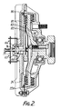
- Referring first to the example of Figure 1, the invention is applied to a viscous clutch of the general type comprising an
internal rotor 10 connected to and driven by a coupling 9 attached to an engine drive shaft (not shown). Therotor 10 is positioned within a twopart casing 11,12 having abearing 13 which supports the casing off the coupling or shaft 9 and the rotor has a series of closely spacedannular rings 15 located respectively in annular grooves in the casing end 12 and in aninternal partition wall 16. This provides a clearance gap on each of the two faces of the rotor of considerably extended area and in operation this clearance gap is filled with a suitable viscous hydraulic fluid to cause torsional drive, or evacuated to allow maximum slip. The invention is concerned more particularly with the control of the fluid in this clearance gap so as to vary the drive from the engine shaft to arotary cooling fan 18 secured to the casing member 12. - In this example a
fluid reservoir 20 is formed between thefront wall 11 and aninternal partition wall 21 and fluid is continuously pumped from the outer periphery of the clearance space by one ormore scoops 22 which convey the oil forwards through anopening 23 into aradial passage 24 leading towards the rotary axis. At the axis there is avalve port 25 through which the fluid flows into thereservoir 20 and returns to the clearance space through a constantlyopen port 26. This port is not of sufficient size to allow all the oil pumped inwards by the scoop to return to the casing. - The flow of oil is controlled by a movable valve stem or plunger 30, which is shifted axially into or out of the
port 25. When closing or partly closing the port the flow of fluid inwards from the scoop is restricted, all the fluid drains from the reservoir through theport 26 and the clearance gap in the clutch is fully flooded with the viscous fluid: this provides maximum drive or drag and thefan 18 is driven at close to shaft speed. By contrast when the valve stem 30 is shifted to the left to open theport 25 the scoop delivers fluid at maximum rate inwards along thepassage 24 and this being faster than the rate of escape through theport 26 fluid builds up within thereservoir 20 and consequently results in a drainage of oil from the clearance gap. The drive through the clutch is therefore reduced, thefan speed 18 falls and the cooling effect on the engine radiator is reduced, as also the power absorbed in the fan drive. - The valve stem 30 is controlled in this example by a combination of coolant temperature with fan speed or scoop pump pressure. The coolant duct is illustrated at 40 which is conveniently the exit from the coolant radiator (not shown). A
wax capsule 41 is positioned in the coolant passage and itsoperating stem 42 is positioned in one end of amovable valve stem 43 of a follow-up pressurecontrol valve unit 44. Thestem 43 moves within an axially floatingspool 45 attached to a piston the upper side of which is exposed to atmospheric pressure and to a balancingspring 46. The underside of the piston is exposed to pneumatic servo-control pressure at 47, which is communicated vialine 48 to the front end of adifferential servo unit 50 at the front end of the clutch casing. Compressed air to operate the system is admitted to thevalve unit 44 at 51, passes through the spool at theport 52 and is controlled by ashoulder 53 on the inner stem. This stem also has atapered end 54 which combines with the spool so that as the coolant temperature rises and the stem lifts the escape of air at theconical end 54 is reduced and flow of pressurised air from theline 51 is increased. The spool correspondingly shifts upwards until the follow-up servo effect recreates the balance with increased force in thespring 46 and increased pressure in the working volume below thepiston 45. Thus, the pressure inline 48 always corresponds to the temperature of the coolant. - In the
differential pressure unit 50 the air pressure inline 48 is reacted against the fluid pressure from thescoop 22. For this purpose a differential piston 61 has asmall piston end 62 exposed to the air pressure inline 48 and alarger piston element 63 exposed to the hydraulic pressure inchamber 64 to which hydraulic fluid is admitted through an internal passage 65 having a lateral inlet opening. This passage effectively communicates at all times with thescoop delivery passage 24. Thus an increase in the air pressure inline 48 caused by an increase in the coolant temperature will cause the valve stem to move to the right to close theport 25 and hence drain thereservoir 20, flood the clearance space, increase the drive to the fan and so indirectly reduce the coolant temperature again. - By contrast if the fluid pressure at the
scoop 22 increases, the pressure involume 64 acts on thepiston 63 to move the valve stem 30 in the opposite direction and so to reduce the drive to the fan. - Thus the system provides automatic control of the level of fluid in the clutch and hence the effective drive to the cooling fan which is dependent upon the relationship between the coolant temperature and the differential speed between the input and output of the clutch. Assuming any selected engine speed this is therefore dependent upon the fan speed. The relationship can be selected and varied, as required, by control of any one of a number of parameters in the system such as the relative sizes of the differential piston areas, the strength of the springs in the pneumatic
pressure control unit 44 and thedifferential piston unit 50, and the size of thevalve orifice 25. - In a possible modification the clutch may be controlled in response to a combination of fan speed and coolant temperature, by means of an air temperature sensing element such as a bi-metal thermal sensing device directly responsive to the temperature of the cooling air flowing over the fan drive clutch. The bi-metal element acts via a spring on a flange at the forward end of a piston stem which carries the differential piston and is attached to the valve plunger as in the previous example. This system thus provides an automatic control of the quantity of fluid in the clutch and hence the drive to the fan in accordance with the relationship between air temperature and fan speed.
- The characteristic behaviour of the viscous drive can be varied also by appropriate design of the return flow path from the
reservoir 20 to the clearance gap. In the example of Figure 1 there is asingle return orifice 26, but it may be preferable to provide a series ofapertures 75,76, 77 etc., as illustrated in Figure 6. With this arrangement it may be preferable that theoutermost aperture 26 should be of reduced size. Hence when fluid is supplied to the reservoir by the scoop pump it will not drain back to the clearance volume at an excessive rate and the return rate will increase progressively as the volume of fluid in the reservoir increases, and the return flow is augmented by theadditional apertures 75,76,77. It is also theoretically possible to achieve a similar result by use of a narrow elongated radial slot which may be of varying width, increasing towards the outer end, if required. - In the modification illustrated in Figure 2, the apparatus has a bi-metal
thermal sensing element 71 acting on the spool or plunger 74. In this case themain scoop pump 22A delivers fluid into the reservoir 20ʹ via the radial passage 24ʹ and there is a second scooptype pressure pump 80 delivering fluid under pressure viapassage 81 into the chamber 64ʺ at the forward end of the piston 63ʺ. The stem 66ʹ of this piston acts on a pivotedlever 82 whoseouter end 83 is arranged to open and close the return aperture 26ʹ from the reservoir. This is in contrast to the arrangement of Figure 1 where thecontrol valve elements 25,30 restricts the flow into the reservoir. - The embodiment illustrated in Figure 3 incorporates certain elements of the examples of Figures 1 and 2. In this arrangement there is a pneumatic input 48ʹ derived from a coolant temperature valve similar to the
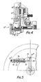
unit 44 in Figure 1. This pneumatic pressure is delivered to the chamber 64ʹ at the forward end of the piston 63ʹ. The clutch has a main scoop pump 22ʺ delivering fluid from the clearance gap into the reservoir 20ʺ via passageway 24ʺ and there is a second controlling scoop pump 80ʹ supplying pressure fluid through passage 81ʹ to the port on the axis formed by the projecting piston plunger 66ʹ. This fluid pressure communicates via the central drilling with the chamber 65ʹ at the rear side of piston 63ʹ. The plunger in this example acts on a double rocking lever 82ʹ whose outer end is arranged to open and close the fluid return aperture 26ʺ allowing fluid to escape from the reservoir 20ʺ and return to the clearance gap. In other respects this is similar to the example of Figure 1 and operates in a comparable manner. - In the example illustrated in Figures 4 and 5 like parts are indicated by similar reference numerals and in this example the bi-metal element 71ʺ is a spiral strip arranged to cause rotation of a
control element 90 which acts through atorsion spring 91 on arotary output lever 92. This lever bears on thevalve stem 93 against the pressure of aspring 94 and controls the position of avalve arm 95 which opens and closes thereturn orifice 26‴. The clutch has a main scoop pump (not shown) similar to the pump 22ʹ shown in the lower part of Figure 2 and, in addition, an auxiliary scoop pressure pump 80ʺ supplying pressure fluid along radial passage 81ʺ to thechamber 96 at the adjacent end of thevalve 97. Thus the scoop pressure which is a measure of clutch speed is opposed to the force exerted on thevalve stem 93 by the bi-metal spiral sensing element 71ʺ. - In the example of Figures 7 and 8 the construction is in some respects similar to the examples of Figures 1 and 3 and like parts are indicated by the same reference numerals with different suffixes. In this case there is a pneumatic input line 48ʺ derived from a coolant temperature valve similar to the
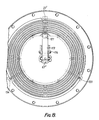
unit 44 in Figure 1. This pneumatic pressure is delivered to the left-hand end of a chamber 64ʺ containing a piston 63ʺ. This acts via bearing 110 on anon-rotary cup 111 engaging thelower end 112 of a rockinglever 113 pivoted at 114. Theupper end 116 of the lever acts as a valve element to open and close a pair of valve ports 118,119 and this same end of the lever is engaged by apiston 121 in a chamber which communciates with radial passage 81ʺ connected to the "scoop" pressure port 23ʹ. The pressure in radial passage 81ʺ is transmitted via radial passage 125 in thepiston 121 to the left-hand end of thechamber 126 and the pressure therefore urges this piston to the right against the rocking lever and opposing the pressure force acting onpiston 63". The net differential pressure force on the lever depends upon the relative cross-sectional areas of the two pistons and the relative lever arms of the two sides of the lever. In other respects this embodiment operates in the same manner as the example of Figure 3. - In this construction of Figures 7 and 8 there are in fact three separate fluid pumping scoops 22ʹ and 133,134 as illustrated in Figure 8. The pressure from scoop 23ʹ is applied to the
piston 121, as described above, but this fluid does not return to the operating chamber of the viscous drive. The other two scoop pump elements 133,134 are arranged to deliver fluid continuously from the periphery of the working chamber to the central reservoir. - It will be noted that in all these examples of the invention the viscous fluid clutch has a casing surrounding an internal rotary member to define a clearance gap which may be occupied by the viscous fluid, and adjacent the periphery of the casing there is provided an impulse type fluid pumping means which generates fluid pressure dependent on the relative speed of rotation between the casing and the inner member.
- In these examples of the invention the thermal sensing device in each case senses the temperature of an external cooling liquid for the engine or of the cooling air passing over the clutch and through the associated cooling fan. This is by contrast with systems having a thermal control element located inside the viscous fluid clutch sensing the viscous fluid temperature.
- In these illustrated examples of the invention the speed derived pressure force is opposed directly to the thermal-derived pressure force to control the valve governing return flow of fluid to the clearance gap. This facilitates proper design of the parts and small tuning adjustments to ensure the proper balance between the two pressure forces over the whole operating range. For example in the Figure 7 embodiment it is a comparatively simple adjustment to alter the pressure loading of the
small spring 140 at the end of the plunger 63ʺ. For example in the Figure 7 embodiment it is a comparatively simple adjustment to replace thesmall spring 140 with a different spring having different pressure loading or other characteristics. This provides a very simple method of altering the balance or relationship between the pump scoop pressure and the thermal sensing pressure. - It will be appreciated that the flow control valve can be applied either to the supply flow of the viscous fluid from the pump to the reservoir or to the return flow from the reservoir to the clearance gap. In some examples, as in Figure 1, the
valve 50 controls the flow through thesupply passage 24 andorifice 25 between thepump 22 and thereservoir 20. In such case it is normal to have a permanently open return port 26 (or a series ofports 75 to 77) and it will be appreciated that an increase in scoop pump pressure in thepassage 24 will cause the valve spindle 61 to move to the left thus opening theport 25 and increasing the flow into the reservoir, which in turn results in a reduction in the quantity of liquid in the clearance gap. Likewise an increase in the thermal sensing pressure in theline 48 causes the valve spindle 61 to move to the right to throttle the flow through theorifice 25 and thus tend to increase the quantity of fluid in the clearance gap. - By contrast in systems, as illustrated in the examples of Figures 2,5 and 7, the fluid pressure delivered by the
scoop pump 22 acts on the valve assembly to regulate the return flow of fluid from the reservoir to the clearance gap via the port 26ʹ, 26ʺ etc. In these cases an increase in scoop pump pressure is arranged to cause the port 26ʹ 119 etc. to be throttled thus reducing the quantity of viscous fluid in the clearance gap. It will be seen that the thermal sensing pressure force is applied in the opposite sense. It will be noted that in these several examples of the invention the scoop pump pressure derived from the relative speed between the clutch components is opposed to the thermal sensing pressure derived from the coolant or air flow and the result is to apply a differential force to the valve which will create large rapid changes in the valve opening and corresponding optimum clutch control. By contrast in any system incorporating a centrifugal speed governor the movements of the valve will be relatively slow and restricted and may cause undesirable speed fluctuations. - It will also be noted that in these examples the
casing 11,12 has a slightly conical periphery as a result of which the viscous fluid drains towards the actual entry of the pump such that substantially all the viscous fluid can be extracted to reduce the drive effectively to zero and allow an extremely low idling speed of the fan.
Claims (14)
- A viscous fluid clutch comprising a rotary casing (11,12) and an inner clutch member (10) within the casing and spaced therefrom by a clearance gap, a reservoir (20) communicating with the clearance gap, and a pump (22) arranged to pump fluid from the clearance gap to the reservoir (20) in response to relative rotation between the casing (11,12) and the inner member (10), a thermal sensor (41,71) for sensing the temperature of a fluid external to the casing and valve means (25,30) controlling the flow of fluid between the pump (22) and the clearance gap, characterised in that the thermal sensor generates a temperature-dependent pressure force and the valve means has a moveable control element (30) acted upon in one direction by said temperature-dependent pressure force and in the opposing direction by the fluid pressure force derived from the pump (22), whereby an increase in pump pressure, or a decrease in the sensed temperature, tends to adjust the valve means (25,30) so as to reduce the quantity of fluid in said clearance gap.
- A viscous fluid clutch according to Claim 1, constituting the drive to a cooling fan (18) for an engine, characterised in that the thermal sensor (41,) is arranged to sense the temperature of a coolant liquid or gas for the engine.
- A viscous fluid clutch according to Claim 1 or Claim 2, characterised by a source (51) of servo fluid under pressure, a pressure regulating valve (44) connected to the thermal sensor (41) to modify the output pressure in accordance with the sensed temperature, and a duct (48) for applying the modified pressure to the control element (62,30) of the valve means.
- A viscous fluid clutch according to any of Claims 1,2 or 3, characterised by a differential piston assembly (61,62) exposed in one direction to the pressure derived from the pump (22) and in the other direction to the pressure derived from the temperature sensor (41).
- A viscous fluid clutch according to Claims 1 or 2, characterised in that the thermal sensor includes a bi-metal thermal sensing element (71) positioned on the casing (11,12) of the clutch and arranged to sense air temperature.
- A viscous fluid clutch according to any of the preceding claims, characterised by two fluid impellers or pumps, one (22" Fig. 3) for transferring fluid from the clearance gap to the reservoir, and the other (80') for generating the fluid control pressure responsive to the relative speed of the components of the clutch.
- A viscous fluid clutch according to any of the preceding claims, characterised in that the valve means (25,26) controls the flow of fluid from the pump (22) to the reservoir (20).
- A viscous fluid clutch according to Claim 7, characterised in that the valve controls a flow port in a supply passage (24,81) between the pump (22) and the reservoir (20), and is arranged to increase the flow through the supply passage in response to a sensed increase in relative speed, so as to reduce the quantity of fluid in the clearance gap.
- A viscous fluid clutch according to any of Claims 1 to 6, characterised in that the valve controls a flow port (26' Fig.2) in a return passage between the reservoir (20) and the clearance gap, and is arranged to reduce the flow through the return passage in response to a sensed increase in relative speed, so as to reduce the quantity of fluid in said clearance gap.
- A viscous fluid clutch according to Claim 8 or 9, characterised in that there is a return path for fluid from the reservoir to the clearance gap, the return path including at least one aperture (26,75,76, etc) in a wall of the reservoir providing for fluid flow at two or more different radial positions from the axis of rotation.
- A viscous fluid clutch according to Claim 10, characterised in that the fluid flow from the reservoir is relatively low at increased radial positions from the axis.
- A viscous fluid clutch according to Claim 10 or 11, characterised in that there are two or more separate return flow apertures at different radial positions.
- A viscous fluid clutch according to Claim 12, characterised in that the outermost aperture is of relatively reduced cross-sectional area.
- A viscous fluid clutch according to any preceding claim, wherein said thermal sensor includes a source (51) of servo fluid under pressure and a valve (44) for modifying this pressure in accordance with the sensed temperature, the valve comprising a first valve element (43) connected to and operated by a thermal sensor (41), and a second valve element (45) having a fluid piston and co-operating with the first valve element to open and close a valve orifice between an input pressure port (52) connected to the pressure source (51), and an output port (47) which communicates with a chamber exposed to one side of the valve, such that changes in the sensed temperature cause movements of the first valve element to open and close the valve and the resultant changes in output pressure exerted on the valve piston cause the second valve member to move in a direction to close the valve and establish the required output pressure.
Priority Applications (1)
| Application Number | Priority Date | Filing Date | Title |
|---|---|---|---|
| AT88300019T ATE75529T1 (en) | 1987-01-07 | 1988-01-05 | AUTOMATIC TEMPERATURE AND SPEED CONTROL FOR FLUID CLUTCH. |
Applications Claiming Priority (2)
| Application Number | Priority Date | Filing Date | Title |
|---|---|---|---|
| GB878700213A GB8700213D0 (en) | 1987-01-07 | 1987-01-07 | Automatic thermal & speed controls |
| GB8700213 | 1987-01-07 |
Related Child Applications (1)
| Application Number | Title | Priority Date | Filing Date |
|---|---|---|---|
| EP91113232.2 Division-Into | 1988-01-05 |
Publications (3)
| Publication Number | Publication Date |
|---|---|
| EP0274408A2 EP0274408A2 (en) | 1988-07-13 |
| EP0274408A3 EP0274408A3 (en) | 1988-10-26 |
| EP0274408B1 true EP0274408B1 (en) | 1992-04-29 |
Family
ID=10610328
Family Applications (2)
| Application Number | Title | Priority Date | Filing Date |
|---|---|---|---|
| EP19910113232 Withdrawn EP0462628A3 (en) | 1987-01-07 | 1988-01-05 | Pressure modulating valve |
| EP88300019A Expired - Lifetime EP0274408B1 (en) | 1987-01-07 | 1988-01-05 | Automatic thermal and speed controls for viscous fluid clutches |
Family Applications Before (1)
| Application Number | Title | Priority Date | Filing Date |
|---|---|---|---|
| EP19910113232 Withdrawn EP0462628A3 (en) | 1987-01-07 | 1988-01-05 | Pressure modulating valve |
Country Status (8)
| Country | Link |
|---|---|
| US (1) | US4909367A (en) |
| EP (2) | EP0462628A3 (en) |
| AT (1) | ATE75529T1 (en) |
| BR (1) | BR8800026A (en) |
| DE (1) | DE3870464D1 (en) |
| GB (1) | GB8700213D0 (en) |
| IN (1) | IN169452B (en) |
| MX (1) | MX161233A (en) |
Families Citing this family (22)
| Publication number | Priority date | Publication date | Assignee | Title |
|---|---|---|---|---|
| US5400823A (en) * | 1989-01-13 | 1995-03-28 | Kysor Industrial Corporation | Viscous fluid shear clutches and control valves therefor |
| CA2007135A1 (en) * | 1989-01-13 | 1990-07-13 | Arthur E. H. Elmer | Viscous fluid shear clutches and control valves therefor |
| US5191915A (en) * | 1989-01-13 | 1993-03-09 | Kysor Industrial Corporation | Viscous fluid shear clutches and control valves therefor |
| US5161659A (en) * | 1989-01-13 | 1992-11-10 | Kysor Industrial Corporation | Viscous fluid shear clutches and control valves therefor |
| US5799765A (en) * | 1990-08-30 | 1998-09-01 | Usui Kokusai Sangyo Kaisha Limited | Fluid clutch |
| JPH0743502U (en) * | 1993-12-30 | 1995-08-22 | 株式会社ユニシアジェックス | Fluid fitting |
| DE4413997C2 (en) * | 1994-04-22 | 1999-01-21 | Mannesmann Sachs Ag | Viscous fan clutch with actuator |
| DE4442451A1 (en) * | 1994-11-29 | 1996-05-30 | Behr Gmbh & Co | Hydraulic friction clutch with clutch drive as drive part |
| US5558192A (en) * | 1995-03-27 | 1996-09-24 | Eaton Corporation | Fluid coupling and external control therefor |
| JP3786374B2 (en) * | 1995-11-10 | 2006-06-14 | 臼井国際産業株式会社 | Liquid clutch |
| DE19604853B4 (en) * | 1996-02-10 | 2006-01-12 | Behr Gmbh & Co. Kg | Elastic torque arm |
| US6092638A (en) * | 1998-03-05 | 2000-07-25 | Horton, Inc. | Splineless rotational control apparatus |
| DE19837595B4 (en) * | 1998-08-19 | 2004-06-03 | Kuka Roboter Gmbh | Method and device for balancing the weight of a robot arm |
| JP2000130165A (en) * | 1998-10-30 | 2000-05-09 | Unisia Jecs Corp | Fan coupling device |
| DE10311347A1 (en) * | 2002-03-29 | 2003-10-09 | Usui Kokusai Sangyo Kk | Temperature-controlled fluid friction clutch for intermittent driving of a cooling fan, especially of an internal combustion engine, comprises an operating pin movably arranged parallel to the surface of a separator |
| US7104382B2 (en) * | 2004-10-21 | 2006-09-12 | Kit Masters Inc. | Clutch system |
| US7438169B2 (en) | 2004-10-21 | 2008-10-21 | Kit Masters Inc. | Clutch system |
| US8100239B2 (en) * | 2008-01-18 | 2012-01-24 | Kit Masters Inc. | Clutch device and methods |
| US8109375B2 (en) * | 2009-05-07 | 2012-02-07 | Kit Masters Inc. | Clutch systems and methods |
| US9046137B2 (en) | 2010-01-22 | 2015-06-02 | Kit Masters Inc. | Fan clutch apparatus and methods |
| US8360219B2 (en) | 2010-04-26 | 2013-01-29 | Kit Masters, Inc. | Clutch system and methods |
| US20140209180A1 (en) * | 2013-01-27 | 2014-07-31 | Rick L. Boyer | Viscous fan drive systems having fill and scavenge control |
Family Cites Families (26)
| Publication number | Priority date | Publication date | Assignee | Title |
|---|---|---|---|---|
| FR1212283A (en) * | 1958-10-01 | 1960-03-23 | Improvements to relief valves | |
| US3159254A (en) * | 1962-01-11 | 1964-12-01 | Schwitzer Corp | Speed responsive coupling device |
| US3144922A (en) * | 1962-04-05 | 1964-08-18 | Schwitzer Corp | Temperature and speed responsive fluid coupling |
| US3363734A (en) * | 1962-09-17 | 1968-01-16 | Eaton Yale & Towne | Temperature responsive fluid clutch |
| US3217849A (en) * | 1962-10-02 | 1965-11-16 | Schwitzer Corp | Speed and temperature controlled coupling device |
| US3191733A (en) * | 1963-01-07 | 1965-06-29 | Schwitzer Corp | Torque transmitting fluid coupling |
| US3194372A (en) * | 1963-03-06 | 1965-07-13 | Schwitzer Corp | Variable volume coupling mechanism |
| US3444748A (en) * | 1967-02-01 | 1969-05-20 | Eaton Yale & Towne | Drive mechanism |
| GB1377476A (en) * | 1970-11-21 | 1974-12-18 | Dynair Ltd | Fan drives |
| GB1395690A (en) * | 1973-12-18 | 1975-05-29 | Dynair Ltd | Thermally actuated control valves |
| US3961606A (en) * | 1975-01-02 | 1976-06-08 | Standard-Thomson Corporation | Thermally responsive fluid control valve |
| US4007819A (en) * | 1975-06-20 | 1977-02-15 | Wallace-Murray Corporation | Fan drive fluid circulation apparatus |
| US4116318A (en) * | 1977-04-05 | 1978-09-26 | Eaton Corporation | Fluid flow restriction path in viscous fluid clutch |
| US4176630A (en) * | 1977-06-01 | 1979-12-04 | Dynair Limited | Automatic control valves |
| US4285467A (en) * | 1977-10-12 | 1981-08-25 | Eaton Corporation | Three-port thermally responsive valve |
| US4189095A (en) * | 1978-11-02 | 1980-02-19 | Kysor Industrial Corporation | Combination valve |
| JPS5927452B2 (en) * | 1978-11-16 | 1984-07-05 | アイシン精機株式会社 | Viscous fluid coupling device |
| US4351426A (en) * | 1980-12-29 | 1982-09-28 | Eaton Corporation | Single stage control for viscous fluid coupling |
| US4467903A (en) * | 1981-02-09 | 1984-08-28 | Aisin Seiki Kabushiki Kaisha | Temperature responsive, pneumatically actuated, fluid shear, cooling fan clutch and control therefor |
| US4437554A (en) * | 1981-06-19 | 1984-03-20 | Household Manufacturing Inc. | Fluid shear coupling apparatus |
| DE3242381C2 (en) * | 1981-11-30 | 1986-05-28 | Aisin Seiki K.K., Kariya, Aichi | Fluid friction clutch |
| DE3211337C2 (en) * | 1982-03-27 | 1984-08-09 | J.M. Voith Gmbh, 7920 Heidenheim | Hydrodynamic control clutch |
| EP0105647A1 (en) * | 1982-09-30 | 1984-04-18 | Household Manufacturing, Inc. | Fluid shear coupling apparatus |
| US4579206A (en) * | 1983-06-29 | 1986-04-01 | Eaton Corporation | Fluid coupling device and valve mechanism for use therein |
| DE3333268A1 (en) * | 1983-09-15 | 1985-04-18 | Süddeutsche Kühlerfabrik Julius Fr. Behr GmbH & Co KG, 7000 Stuttgart | METHOD FOR CONTROLLING THE OUTPUT SPEED OF A LIQUID FRICTION CLUTCH AND DEVICE FOR CARRYING OUT THE METHOD |
| US4653624A (en) * | 1986-05-27 | 1987-03-31 | Household Manufacturing, Inc. | Fluid shear coupling apparatus having fluid modulating valve |
-
1987
- 1987-01-07 GB GB878700213A patent/GB8700213D0/en active Pending
-
1988
- 1988-01-05 EP EP19910113232 patent/EP0462628A3/en not_active Withdrawn
- 1988-01-05 EP EP88300019A patent/EP0274408B1/en not_active Expired - Lifetime
- 1988-01-05 AT AT88300019T patent/ATE75529T1/en not_active IP Right Cessation
- 1988-01-05 DE DE8888300019T patent/DE3870464D1/en not_active Expired - Lifetime
- 1988-01-05 US US07/140,990 patent/US4909367A/en not_active Expired - Fee Related
- 1988-01-06 IN IN13/CAL/88A patent/IN169452B/en unknown
- 1988-01-06 BR BR8800026A patent/BR8800026A/en unknown
- 1988-01-07 MX MX10016A patent/MX161233A/en unknown
Also Published As
| Publication number | Publication date |
|---|---|
| IN169452B (en) | 1991-10-19 |
| DE3870464D1 (en) | 1992-06-04 |
| MX161233A (en) | 1990-08-24 |
| EP0462628A2 (en) | 1991-12-27 |
| ATE75529T1 (en) | 1992-05-15 |
| EP0462628A3 (en) | 1992-02-26 |
| GB8700213D0 (en) | 1987-02-11 |
| EP0274408A3 (en) | 1988-10-26 |
| US4909367A (en) | 1990-03-20 |
| BR8800026A (en) | 1988-08-02 |
| EP0274408A2 (en) | 1988-07-13 |
Similar Documents
| Publication | Publication Date | Title |
|---|---|---|
| EP0274408B1 (en) | Automatic thermal and speed controls for viscous fluid clutches | |
| US3664129A (en) | Hydraulic cooling system | |
| US6321527B1 (en) | Bi-level fuel pressurizing system | |
| KR920008643B1 (en) | Temperature-controlled fan fluid coupling | |
| US4201050A (en) | Fluid coupling | |
| US4203712A (en) | Single or plural variable displacement pump control with an improved flow metering valve | |
| CA1048895A (en) | Valves for fluid couplings | |
| GB2125150A (en) | Warm-up promotion device for automatic transmission | |
| US6135135A (en) | Force balanced proportional bypass valve | |
| US4591317A (en) | Dual pump controls | |
| US2530241A (en) | Power transmission for refrigerated motor vehicles | |
| JPH0355698B2 (en) | ||
| US4072443A (en) | Control valve arrangements for variable stroke pumps | |
| US5277028A (en) | Hydraulic flow control with temperature sensitive spring biased bypass valve | |
| EP0378341B1 (en) | Viscous fluid shear clutches and control valves therefor | |
| JPH0356328B2 (en) | ||
| US6494797B1 (en) | Automatic transmission assembly and method of operating the same | |
| JPH05263766A (en) | Hydraulic system for hydraulic machine | |
| US3128822A (en) | tyler | |
| US4441598A (en) | Modulated viscous fan drive | |
| US3964506A (en) | Pressure control system | |
| US4924986A (en) | Viscous fluid clutches | |
| US4426196A (en) | Oil supply system | |
| US5191915A (en) | Viscous fluid shear clutches and control valves therefor | |
| US5400823A (en) | Viscous fluid shear clutches and control valves therefor |
Legal Events
| Date | Code | Title | Description |
|---|---|---|---|
| PUAI | Public reference made under article 153(3) epc to a published international application that has entered the european phase |
Free format text: ORIGINAL CODE: 0009012 |
|
| AK | Designated contracting states |
Kind code of ref document: A2 Designated state(s): AT BE CH DE ES FR GB IT LI LU NL SE |
|
| PUAL | Search report despatched |
Free format text: ORIGINAL CODE: 0009013 |
|
| AK | Designated contracting states |
Kind code of ref document: A3 Designated state(s): AT BE CH DE ES FR GB IT LI LU NL SE |
|
| 17P | Request for examination filed |
Effective date: 19890410 |
|
| 17Q | First examination report despatched |
Effective date: 19900220 |
|
| RAP1 | Party data changed (applicant data changed or rights of an application transferred) |
Owner name: KYSOR INDUSTRIAL CORPORATION |
|
| GRAA | (expected) grant |
Free format text: ORIGINAL CODE: 0009210 |
|
| AK | Designated contracting states |
Kind code of ref document: B1 Designated state(s): AT BE CH DE ES FR GB IT LI LU NL SE |
|
| PG25 | Lapsed in a contracting state [announced via postgrant information from national office to epo] |
Ref country code: IT Free format text: LAPSE BECAUSE OF FAILURE TO SUBMIT A TRANSLATION OF THE DESCRIPTION OR TO PAY THE FEE WITHIN THE PRE;WARNING: LAPSES OF ITALIAN PATENTS WITH EFFECTIVE DATE BEFORE 2007 MAY HAVE OCCURRED AT ANY TIME BEFORE 2007. THE CORRECT EFFECTIVE DATE MAY BE DIFFERENT FROM THE ONE RECORDED.SCRIBED TIME-LIMIT Effective date: 19920429 Ref country code: CH Effective date: 19920429 Ref country code: LI Effective date: 19920429 Ref country code: NL Effective date: 19920429 Ref country code: SE Effective date: 19920429 Ref country code: AT Effective date: 19920429 Ref country code: BE Effective date: 19920429 Ref country code: ES Free format text: THE PATENT HAS BEEN ANNULLED BY A DECISION OF A NATIONAL AUTHORITY Effective date: 19920429 |
|
| REF | Corresponds to: |
Ref document number: 75529 Country of ref document: AT Date of ref document: 19920515 Kind code of ref document: T |
|
| REF | Corresponds to: |
Ref document number: 3870464 Country of ref document: DE Date of ref document: 19920604 |
|
| ET | Fr: translation filed | ||
| REG | Reference to a national code |
Ref country code: CH Ref legal event code: PL |
|
| NLV1 | Nl: lapsed or annulled due to failure to fulfill the requirements of art. 29p and 29m of the patents act | ||
| PG25 | Lapsed in a contracting state [announced via postgrant information from national office to epo] |
Ref country code: GB Effective date: 19930105 |
|
| PG25 | Lapsed in a contracting state [announced via postgrant information from national office to epo] |
Ref country code: LU Free format text: LAPSE BECAUSE OF NON-PAYMENT OF DUE FEES Effective date: 19930131 |
|
| PLBE | No opposition filed within time limit |
Free format text: ORIGINAL CODE: 0009261 |
|
| STAA | Information on the status of an ep patent application or granted ep patent |
Free format text: STATUS: NO OPPOSITION FILED WITHIN TIME LIMIT |
|
| 26N | No opposition filed | ||
| GBPC | Gb: european patent ceased through non-payment of renewal fee |
Effective date: 19930105 |
|
| PG25 | Lapsed in a contracting state [announced via postgrant information from national office to epo] |
Ref country code: FR Effective date: 19930930 |
|
| PG25 | Lapsed in a contracting state [announced via postgrant information from national office to epo] |
Ref country code: DE Effective date: 19931001 |
|
| REG | Reference to a national code |
Ref country code: FR Ref legal event code: ST |