EP0274178B1 - Volumetric withdrawal of fluid - Google Patents
Volumetric withdrawal of fluid Download PDFInfo
- Publication number
- EP0274178B1 EP0274178B1 EP87304378A EP87304378A EP0274178B1 EP 0274178 B1 EP0274178 B1 EP 0274178B1 EP 87304378 A EP87304378 A EP 87304378A EP 87304378 A EP87304378 A EP 87304378A EP 0274178 B1 EP0274178 B1 EP 0274178B1
- Authority
- EP
- European Patent Office
- Prior art keywords
- fluid
- filter
- patient
- pump
- ultrafiltrate
- Prior art date
- Legal status (The legal status is an assumption and is not a legal conclusion. Google has not performed a legal analysis and makes no representation as to the accuracy of the status listed.)
- Expired - Lifetime
Links
- 239000012530 fluid Substances 0.000 title claims description 65
- 238000004891 communication Methods 0.000 claims description 16
- 239000000706 filtrate Substances 0.000 claims description 9
- 238000002616 plasmapheresis Methods 0.000 claims description 4
- 239000008280 blood Substances 0.000 description 19
- 210000004369 blood Anatomy 0.000 description 19
- 239000000835 fiber Substances 0.000 description 11
- 238000001631 haemodialysis Methods 0.000 description 6
- 230000000322 hemodialysis Effects 0.000 description 6
- 238000002615 hemofiltration Methods 0.000 description 6
- 238000000034 method Methods 0.000 description 6
- 230000036772 blood pressure Effects 0.000 description 5
- 210000001367 artery Anatomy 0.000 description 4
- DDRJAANPRJIHGJ-UHFFFAOYSA-N creatinine Chemical compound CN1CC(=O)NC1=N DDRJAANPRJIHGJ-UHFFFAOYSA-N 0.000 description 4
- 239000000047 product Substances 0.000 description 4
- 210000003462 vein Anatomy 0.000 description 4
- 239000002699 waste material Substances 0.000 description 4
- 238000001802 infusion Methods 0.000 description 3
- 230000002572 peristaltic effect Effects 0.000 description 3
- 239000011148 porous material Substances 0.000 description 3
- 238000000108 ultra-filtration Methods 0.000 description 3
- ZLMJMSJWJFRBEC-UHFFFAOYSA-N Potassium Chemical compound [K] ZLMJMSJWJFRBEC-UHFFFAOYSA-N 0.000 description 2
- 230000017531 blood circulation Effects 0.000 description 2
- 230000023555 blood coagulation Effects 0.000 description 2
- 229940109239 creatinine Drugs 0.000 description 2
- 230000001419 dependent effect Effects 0.000 description 2
- 238000001914 filtration Methods 0.000 description 2
- 239000012528 membrane Substances 0.000 description 2
- 229910052700 potassium Inorganic materials 0.000 description 2
- 239000011591 potassium Substances 0.000 description 2
- 238000004382 potting Methods 0.000 description 2
- 238000005086 pumping Methods 0.000 description 2
- LFOIDLOIBZFWDO-UHFFFAOYSA-N 2-methoxy-6-[6-methoxy-4-[(3-phenylmethoxyphenyl)methoxy]-1-benzofuran-2-yl]imidazo[2,1-b][1,3,4]thiadiazole Chemical compound N1=C2SC(OC)=NN2C=C1C(OC1=CC(OC)=C2)=CC1=C2OCC(C=1)=CC=CC=1OCC1=CC=CC=C1 LFOIDLOIBZFWDO-UHFFFAOYSA-N 0.000 description 1
- 208000009304 Acute Kidney Injury Diseases 0.000 description 1
- 206010016803 Fluid overload Diseases 0.000 description 1
- HTTJABKRGRZYRN-UHFFFAOYSA-N Heparin Chemical compound OC1C(NC(=O)C)C(O)OC(COS(O)(=O)=O)C1OC1C(OS(O)(=O)=O)C(O)C(OC2C(C(OS(O)(=O)=O)C(OC3C(C(O)C(O)C(O3)C(O)=O)OS(O)(=O)=O)C(CO)O2)NS(O)(=O)=O)C(C(O)=O)O1 HTTJABKRGRZYRN-UHFFFAOYSA-N 0.000 description 1
- 208000001953 Hypotension Diseases 0.000 description 1
- 208000033626 Renal failure acute Diseases 0.000 description 1
- 230000001154 acute effect Effects 0.000 description 1
- 201000011040 acute kidney failure Diseases 0.000 description 1
- 208000012998 acute renal failure Diseases 0.000 description 1
- 239000003146 anticoagulant agent Substances 0.000 description 1
- 229940127219 anticoagulant drug Drugs 0.000 description 1
- 230000036770 blood supply Effects 0.000 description 1
- 210000001124 body fluid Anatomy 0.000 description 1
- 239000010839 body fluid Substances 0.000 description 1
- 150000001875 compounds Chemical class 0.000 description 1
- 230000001351 cycling effect Effects 0.000 description 1
- 230000007423 decrease Effects 0.000 description 1
- 238000009792 diffusion process Methods 0.000 description 1
- 238000006073 displacement reaction Methods 0.000 description 1
- 238000002637 fluid replacement therapy Methods 0.000 description 1
- 229960002897 heparin Drugs 0.000 description 1
- 229920000669 heparin Polymers 0.000 description 1
- 239000012510 hollow fiber Substances 0.000 description 1
- 238000010348 incorporation Methods 0.000 description 1
- 208000017169 kidney disease Diseases 0.000 description 1
- 208000012866 low blood pressure Diseases 0.000 description 1
- 238000004519 manufacturing process Methods 0.000 description 1
- 239000000463 material Substances 0.000 description 1
- 238000012959 renal replacement therapy Methods 0.000 description 1
- 238000007873 sieving Methods 0.000 description 1
- 238000006467 substitution reaction Methods 0.000 description 1
- 238000012546 transfer Methods 0.000 description 1
- 238000011282 treatment Methods 0.000 description 1
Images

Classifications
-
- A—HUMAN NECESSITIES
- A61—MEDICAL OR VETERINARY SCIENCE; HYGIENE
- A61M—DEVICES FOR INTRODUCING MEDIA INTO, OR ONTO, THE BODY; DEVICES FOR TRANSDUCING BODY MEDIA OR FOR TAKING MEDIA FROM THE BODY; DEVICES FOR PRODUCING OR ENDING SLEEP OR STUPOR
- A61M1/00—Suction or pumping devices for medical purposes; Devices for carrying-off, for treatment of, or for carrying-over, body-liquids; Drainage systems
- A61M1/34—Filtering material out of the blood by passing it through a membrane, i.e. hemofiltration or diafiltration
-
- A—HUMAN NECESSITIES
- A61—MEDICAL OR VETERINARY SCIENCE; HYGIENE
- A61M—DEVICES FOR INTRODUCING MEDIA INTO, OR ONTO, THE BODY; DEVICES FOR TRANSDUCING BODY MEDIA OR FOR TAKING MEDIA FROM THE BODY; DEVICES FOR PRODUCING OR ENDING SLEEP OR STUPOR
- A61M1/00—Suction or pumping devices for medical purposes; Devices for carrying-off, for treatment of, or for carrying-over, body-liquids; Drainage systems
- A61M1/34—Filtering material out of the blood by passing it through a membrane, i.e. hemofiltration or diafiltration
- A61M1/3403—Regulation parameters
- A61M1/341—Regulation parameters by measuring the filtrate rate or volume
-
- Y—GENERAL TAGGING OF NEW TECHNOLOGICAL DEVELOPMENTS; GENERAL TAGGING OF CROSS-SECTIONAL TECHNOLOGIES SPANNING OVER SEVERAL SECTIONS OF THE IPC; TECHNICAL SUBJECTS COVERED BY FORMER USPC CROSS-REFERENCE ART COLLECTIONS [XRACs] AND DIGESTS
- Y10—TECHNICAL SUBJECTS COVERED BY FORMER USPC
- Y10S—TECHNICAL SUBJECTS COVERED BY FORMER USPC CROSS-REFERENCE ART COLLECTIONS [XRACs] AND DIGESTS
- Y10S210/00—Liquid purification or separation
- Y10S210/929—Hemoultrafiltrate volume measurement or control processes
Definitions
- This invention relates to volumetric withdrawal of fluid. More particularly, the present invention relates to systems and equipment sets used for the withdrawal of fluids from a patient. In particular, the present invention relates to a system which disposes of body fluids containing waste products in the form of solutes. The present invention is particularly, but not exclusively, useful in the health care field for continuous arteriovenous hemofiltration.
- hemodialysis performs selective removal of solutes, such as creatinine, blood-urea-nitrogen (BUN) and potassium from the blood system.
- solutes such as creatinine, blood-urea-nitrogen (BUN) and potassium from the blood system.
- BUN blood-urea-nitrogen
- CAVH is nonselective in its removal of these solutes from the blood system. More specifically, in hemodialysis blood is passed through a filter which is surrounded by a dialysate. Through the process of diffusion, the solutes dissolved within the blood pass through the membrane of the filter and diffuse into the dialysate. Thus, with hemodialysis there is little, if any, loss of fluid volume during the process.
- CAVH Unlike hemodialysis, CAVH operates on the principle that the removal of a given volume of fluids containing solutes proportionately decreases the amount of solutes in the blood system. This removal, however, obviously requires a fluid volume bulk replacement. Though this need for fluid replacement is not disadvantageous, it cannot be overlooked in the set up of a CAVH system and must be considered in order to maintain proper patient fluid balance.
- the present invention is concerned with a CAVH type system.
- CAVH CAVH type system.
- such systems are well known in the pertinent art and have been variously described in the appropriate literature.
- the article: American Journal of Kidney Diseases VI, December 1985, entitled Continuous Arteriovenous Hemofiltration in Acute Renal Failure, by T.A Golper describes the basic elements and functioning of a CAVH system.
- Necessary for such a system is the incorporation of a hemofilter for filtering the unwanted solutes from the blood.
- Such a solution of solutes is commonly known as ultrafiltrate and it will, therefore, be referred to as such herinafter.
- a CAVH system requires the establishment of a blood flow line from an artery of the patient through the filter and back into a vein of the patient.
- the ultrafiltrate is withdrawn from the filter while the blood continues to flow on through the blood flow line to the patient. After being withdrawn from the filter, the ultrafiltrate is passed through a filtrate port for disposal.
- the volume of ultrafiltrate which is withdrawn from the patient is proportional to the amount of solutes which are withdrawn from the patient's blood supply system.
- the volume of withdrawn ultrafiltrate directly affects the level of solutes within the patient's blood system.
- a CAVH system as just described must depend on the patient's own blood pressure for movement of blood through the system. This can give rise to several problems. For example, at low blood pressures the potential for blood clotting within the filter is increased. Further, the amount of blood being filtered is reduced.
- an IV peristaltic pump be incorporated into the ultrafiltrate line.
- SCUS Slow Continuous Ultrafiltration
- CAVH Continous Arteriovenous Hemofiltration
- a peristaltic pump requires head pressure to maintain its accuracy.
- volumetric inaccuracies are encountered.
- neither a clamp nor a linear peristaltic pump in the ultrafiltrate line can provide a routinely reliable system. With either device, the system is still dependent upon the patient's own blood pressure for its operation.
- a volumetric pump is incorporated in the ultrofiltrate line in association with a positive displacement blood pump in the blood line ahead of the filter.
- This system introduces, however a considerable complexity and still does not allow a predetermination of the ultrafiltration volumetric rate with satisfactory accuracy.
- the present invention recognizes that such a device can be established by a volumetric pump which is capable of withdrawing precisely established volumes of ultrafiltrate at a predetermined rate. Further, the present invention recognizes that such a system can function independently of the patient's blood pressure. The present invention also recognizes there is a need for an apparatus in the ultrafiltrate line which is capable of proper operation independently of the head pressure within the system. The present invention further recognizes that a system, such as here envisioned, can be used for plasmapheresis as well as CAVH and that this added feature can be accomplished through the proper selection of appropriate filters.
- the preferred embodiment of the system for volumetric withdrawal of fluids from a patient includes a filter assembly which has an arterial port in fluid communication with an artery of the patient. Further, the filter assembly of this embodiment includes a venous port which is in fluid communication with a vein of the patient and a filtrate port which is connected in fluid communication with a volumetric pump.
- operation of the volumetric pump causes ultrafiltrate fluid to be withdrawn from the filter assembly and into the pump chamber at a predetermined rate.
- valve means within the pump allows for alternatingly withdrawing ultrafiltrate from the filter and emptying the ultrafiltrate from the pump's fluid chamber into a fluid collection device.
- electronic programmable means associated with the pump causes the empty cycle to be done at a rate which is much higher than that for the withdrawal of ultrafiltrate fluid from the patient.
- the fluid volumetric withdrawal system may also include fluid sources appropriately attached to the arterial line or the venous line to permit fluid volume bulk replacement for the patient. Further, the system may permit substitution of the hemofilter with a plasmapheresis filter.
- the fluid volumetric withdrawal system of the present invention includes a filter 12.
- filter 12 may be either a hemofilter or a plasmapheresis filter depending upon the particular desires and needs of the operator. It will be understood by the skilled artesan that the distinction between a hemofilter and phasmapheresis filter lies in the size of pores which are incorporated into the filtering material.
- filter 12 is formed with an arterial port 14 which is connected in fluid communication with arterial line 16.
- Arterial line 16 is connected directly from filter 12 into an artery of the patient 18.
- fluid coursing through the patient's body 18 enters arterial line 16 and passes therethrough to the filter 12.
- Filter 12 also includes a venous port 20 which is connectable in fluid communication with a venous line 22. As shown, venous line 22 is connected directly from filter 12 into a vein of the patient 18. Filter 12 further includes a filtrate port 24 which is connected to a filtrate line 26 that establishes fluid communication betwen the filter 12 and IV pump 28.
- pump 28 is formed with an inlet 30 and an outlet 32.
- a valve 34 having a passageway 36 formed therethrough is rotatably mounted on pump 28 to alternatingly establish fluid communication between chamber 38 of pump 28 and either inlet 30 or outlet 32.
- the operation of system 10 is dependent upon the movement of plunger 40 within chamber 38 as caused by the reciprocal action of piston 42.
- Figure 1 also shows that filtrate line 26 is continued from pump 28, through outlet 32, and terminates with its connection to a fluid collection device 44. The exact operation of system 10 is accomplished in a manner to be subsequently described in detail.
- filter 12 includes a housing 46 which is generally formed as a hollow cylinder.
- An end cap 48 which includes arterial port 14 covers one end of housing 46.
- a similar end cap 50 which includes venous port 20.
- Contained within housing 46 of filter 12 between ends caps 48 and 50 is a fiber bundle 52.
- fiber bundle 52 includes a plurality of hollow tubular shaped fibers and that the pore sizes in the walls of the hollow fibers which comprise the fiber bundle 52 can be varied during manufacture.
- fiber bundle 52 can be selected with various sieving capabilities depending on the particular use intended for system 10.
- fiber bundle 52 is held within housing 46 by potting compound 54 and potting compound 56 included at the respective ends of fiber bundle 52.
- filter 12 A detailed description of a filter such as filter 12 is provided in an article entitled Mass Transfer and Arterial Venous Hemofiltration by M.J. Lysaght et al., as published in Arterial Venous Hemofiltration published by Spriger-Verlag, Berlin, Heidelberg 1985.
- system 10 can incorporate additional elements.
- a fluid source 58 is shown connected in fluid communication with venous line 22. Fluid from source 58 can be infused to patient 18 for the purpose of providing fluid volume bulk replacement. As is well understood by the skilled artesan, fluid volume bulk replacement is necessary in a CAVH system to maintain proper fluid level for the patient.
- fluid source 58 is shown connected to venous line 22 for postdilution of the filtered blood, it is to be understood that a predilution is possible in a system wherein a fluid course (not shown) is connected in fluid communication with arterial line 16. Either configuration is efficacious for the intended purpose.
- a pump 60 may be incorporated into the system to infuse an anticoagulant, such as heparin, for the purpose of preventing blood clotting at filter 12.
- filter 12 is connected in fluid communication with an artery of patient 18 via arterial line 16. Also filter 12 is connected to a vein of patient 18 via venous line 22. As blood passes through arterial line 16 and into filter 12, it comes into contact with fiber bundle 52. It will be understood by the skilled artesan that as blood passes through fiber bundle 52 that an ultrafiltrate, containing solutes such as creatinine, BUN and potassium, passes through the pores and membranes (not shown) of fiber bundle 52 and collects within housing 46. This ultrafiltrate solution eventually passes out of filter 12 via filtrate port 24. While ultrafiltrate is being collected in the housing 42, the filtered blood continues to pass through fiber bundle 52 and exits from filter 12 via venous port 20 from which it passes through venous line 22 and back to patient 18.
- an ultrafiltrate containing solutes such as creatinine, BUN and potassium
- valve 34 positioned to establish fluid communication between filtrate line 26 and chamber 38.
- piston 42 is reciprocally moved to displace plunger 40 in a direction indicated by arrows 62, ultrafiltrate will be drawn from filter 12 and into the chamber 38 via inlet 30.
- valve 34 is rotated to a position as shown in Figure 4.
- valve 34 When valve 34 is positioned as shown in Figure 4, passageway 36 establishes fluid communication between chamebr 38 and outlet 32 and an advancement of plunger 40 into chamber 38 by actuating of piston 42 in a direction indicated by arrows 64 causes the ultrafiltrate that had been collected in chamber 38 to be expelled out of outlet 32.
- valve 34 can be alternatingly moved between its position in Figure 3 to its position as shown in Figure 4 to sequentially draw ultrafiltrate from filter 12 and then expel the collected ultrafiltrate via outlet 32 through a line to fluid collection device 44.
- the pump 28 is electronically controlled in a manner which provides for a relatively slow drawing of ultrafiltrate from filter 12.
- the filling cycle for chamber 38 is accomplished over a relatively extended period of time.
- the expulsion of ultrafiltrate from chamber 38 and into fluid collection device 44 is accomplished within a relatively short period of time. This is done to allow for as continous a withdrawal process of ultrafiltrate from filter 12 as can be possible.
- the IV infusion pump described in U.S. Patent No. 3,985,133 to Jenkins is suitable for use with the present invention it must be modified to operate on a cycle which is essentially the reverse of the cyling requirements needed for the proper operation of the system 10.
- this cycling sequence is intended to accomplish a substantially continuous withdrawal of ultrafiltrate from filter 12.
Landscapes
- Health & Medical Sciences (AREA)
- Heart & Thoracic Surgery (AREA)
- Vascular Medicine (AREA)
- Engineering & Computer Science (AREA)
- Anesthesiology (AREA)
- Biomedical Technology (AREA)
- Hematology (AREA)
- Life Sciences & Earth Sciences (AREA)
- Animal Behavior & Ethology (AREA)
- General Health & Medical Sciences (AREA)
- Public Health (AREA)
- Veterinary Medicine (AREA)
- External Artificial Organs (AREA)
Description
- This invention relates to volumetric withdrawal of fluid. More particularly, the present invention relates to systems and equipment sets used for the withdrawal of fluids from a patient. In particular, the present invention relates to a system which disposes of body fluids containing waste products in the form of solutes. The present invention is particularly, but not exclusively, useful in the health care field for continuous arteriovenous hemofiltration.
- The need to remove excess fluid or fluid containing dissolved waste products from selected patients have been long recognized. It is well known that certain conditions cause the build up of waste products within the body's blood system that necessitates their removal prior to the onset of further complications. Further, it is well known that the removal of dissolved waste products from the body's blood system can be accomplished through at least two well known procedures. These procedures are hemodialysis and continuous arteriovenous hemofiltration (CAVH).
- The basic difference between hemodialysis and CAVH is quite elementary. On the one hand, hemodialysis performs selective removal of solutes, such as creatinine, blood-urea-nitrogen (BUN) and potassium from the blood system. On the other hand, CAVH is nonselective in its removal of these solutes from the blood system. More specifically, in hemodialysis blood is passed through a filter which is surrounded by a dialysate. Through the process of diffusion, the solutes dissolved within the blood pass through the membrane of the filter and diffuse into the dialysate. Thus, with hemodialysis there is little, if any, loss of fluid volume during the process. Unlike hemodialysis, CAVH operates on the principle that the removal of a given volume of fluids containing solutes proportionately decreases the amount of solutes in the blood system. This removal, however, obviously requires a fluid volume bulk replacement. Though this need for fluid replacement is not disadvantageous, it cannot be overlooked in the set up of a CAVH system and must be considered in order to maintain proper patient fluid balance.
- The present invention is concerned with a CAVH type system. As previously implied, such systems are well known in the pertinent art and have been variously described in the appropriate literature. For instance, the article: American Journal of Kidney Diseases VI, December 1985, entitled Continuous Arteriovenous Hemofiltration in Acute Renal Failure, by T.A Golper describes the basic elements and functioning of a CAVH system. Necessary for such a system is the incorporation of a hemofilter for filtering the unwanted solutes from the blood. Such a solution of solutes is commonly known as ultrafiltrate and it will, therefore, be referred to as such herinafter. As described by Dr. Golper, a CAVH system requires the establishment of a blood flow line from an artery of the patient through the filter and back into a vein of the patient. In accordance with CAVH, as blood passes through the filter, the ultrafiltrate is withdrawn from the filter while the blood continues to flow on through the blood flow line to the patient. After being withdrawn from the filter, the ultrafiltrate is passed through a filtrate port for disposal.
- It has been recognized that the volume of ultrafiltrate which is withdrawn from the patient is proportional to the amount of solutes which are withdrawn from the patient's blood supply system. Thus, the volume of withdrawn ultrafiltrate directly affects the level of solutes within the patient's blood system.
- Without artificial assistance, a CAVH system as just described must depend on the patient's own blood pressure for movement of blood through the system. This can give rise to several problems. For example, at low blood pressures the potential for blood clotting within the filter is increased. Further, the amount of blood being filtered is reduced.
- Since the ability to control the volumetric rate of ultrafiltrate withdrawal will establish an accurate and effective CAVH system, various means have been proposed to accomplish this purpose. Typically such means are directly associated with the fluid line connecting the filter with a fluid collection device. One such means is a simple clamp that operates as disclosed in the article: Journal of Critical Care Nurse, July/August 1984, entitled Continuous Ultrafiltration - A New ICU Procedure for the Treatment of Fluid Overload by Williams et al. With a clamp in the ultrafiltrate line leading from the filter, the volumetric flow rate can be somewhat controlled to establish a reasonable approximation of the desired volume withdrawn.
- It has also be proposed that an IV peristaltic pump be incorporated into the ultrafiltrate line. Such a combination is disclosed in the article The Practical Technical Aspects of Slow Continuous Ultrafiltration (SCUS and Continous Arteriovenous Hemofiltration (CAVH) by S. Swann et al., as published in Acute Continuous Renal Replacement Therapy, published by Martinus Nijofff, Boston, Dordrecht Lancaster, 1986. A peristaltic pump, however, requires head pressure to maintain its accuracy. Thus, at low patient blood pressure levels, volumetric inaccuracies are encountered. Thus, neither a clamp nor a linear peristaltic pump in the ultrafiltrate line can provide a routinely reliable system. With either device, the system is still dependent upon the patient's own blood pressure for its operation.
- In a further example of such means, as disclosed in EP-A-0 184 040, a volumetric pump is incorporated in the ultrofiltrate line in association with a positive displacement blood pump in the blood line ahead of the filter. This system introduces, however a considerable complexity and still does not allow a predetermination of the ultrafiltration volumetric rate with satisfactory accuracy.
- In light of the above, there is a need for a device that can be incorporated into a CAVH system which will provide for the accurate, efficient and reliable withdrawal of a predetermined volume of ultrafiltrate while operating within a pressure range which is compatible with the safety and well being of the patient. Also, there is a need for a CAVH system which can properly operate under artificially induced pressure independently of the patient's blood pressure.
- The present invention recognizes that such a device can be established by a volumetric pump which is capable of withdrawing precisely established volumes of ultrafiltrate at a predetermined rate. Further, the present invention recognizes that such a system can function independently of the patient's blood pressure. The present invention also recognizes there is a need for an apparatus in the ultrafiltrate line which is capable of proper operation independently of the head pressure within the system. The present invention further recognizes that a system, such as here envisioned, can be used for plasmapheresis as well as CAVH and that this added feature can be accomplished through the proper selection of appropriate filters.
- It is an object of the present invention to provide a system for the withdrawal of a predetermined volume of fluid from a patient which is independent of the head pressure in the system. It is another object of the present invention to provide a fluid withdrawal system which accurately and reliably withdraws a predetermined volume of fluid at a preselected volumetric rate. Yet another object of the present invention is to provide a system for the withdrawal of fluids from a patient which is easily set up and maintained. Still another object of the present invention is to provide a fluid withdrawal system which is cost effective and efficiently operated.
- According to this invention there is provided a system for volumetric withdrawal of fluid from a patient as defined in claim 1
- The preferred embodiment of the system for volumetric withdrawal of fluids from a patient includes a filter assembly which has an arterial port in fluid communication with an artery of the patient. Further, the filter assembly of this embodiment includes a venous port which is in fluid communication with a vein of the patient and a filtrate port which is connected in fluid communication with a volumetric pump.
- In this embodiment, operation of the volumetric pump causes ultrafiltrate fluid to be withdrawn from the filter assembly and into the pump chamber at a predetermined rate. Also, in this embodiment valve means within the pump allows for alternatingly withdrawing ultrafiltrate from the filter and emptying the ultrafiltrate from the pump's fluid chamber into a fluid collection device. Further, in this embodiment, electronic programmable means associated with the pump causes the empty cycle to be done at a rate which is much higher than that for the withdrawal of ultrafiltrate fluid from the patient.
- The fluid volumetric withdrawal system may also include fluid sources appropriately attached to the arterial line or the venous line to permit fluid volume bulk replacement for the patient. Further, the system may permit substitution of the hemofilter with a plasmapheresis filter.
- Reference is now made to the accompanying drawings, in which:-
- Figure 1 is a schematic view of the volumetric fluid withdrawal system in an operational environment;
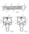
- Figure 2 is a side view of the filter with portions broken away and shown in cross-section for clarity;
- Figure 3 is a cross-sectional view of the pumping mechanism of a volumetric pump oriented for withdrawing fluids from the filter; and
- Figure 4 is a cross-sectional view of the pumping mechanism of a volumetric pump oriented for expelling fluids to a fluid collection device.
- Referring initially to Figure 1, it can be seen that the fluid volumetric withdrawal system of the present invention, generally designated 10, includes a
filter 12. For purposes of the present invention, filter 12 may be either a hemofilter or a plasmapheresis filter depending upon the particular desires and needs of the operator. It will be understood by the skilled artesan that the distinction between a hemofilter and phasmapheresis filter lies in the size of pores which are incorporated into the filtering material. As shown in Figure 1, filter 12 is formed with anarterial port 14 which is connected in fluid communication witharterial line 16.Arterial line 16 is connected directly fromfilter 12 into an artery of thepatient 18. Thus, fluid coursing through the patient'sbody 18 entersarterial line 16 and passes therethrough to thefilter 12. -
Filter 12 also includes avenous port 20 which is connectable in fluid communication with a venous line 22. As shown, venous line 22 is connected directly fromfilter 12 into a vein of thepatient 18.Filter 12 further includes afiltrate port 24 which is connected to afiltrate line 26 that establishes fluid communication betwen thefilter 12 andIV pump 28. - Still referring to Figure 1, it can be seen that
pump 28 is formed with aninlet 30 and anoutlet 32. Avalve 34 having apassageway 36 formed therethrough is rotatably mounted onpump 28 to alternatingly establish fluid communication betweenchamber 38 ofpump 28 and eitherinlet 30 oroutlet 32. As will be appreciated by the skilled artesan, the operation ofsystem 10 is dependent upon the movement ofplunger 40 withinchamber 38 as caused by the reciprocal action ofpiston 42. Figure 1 also shows thatfiltrate line 26 is continued frompump 28, throughoutlet 32, and terminates with its connection to afluid collection device 44. The exact operation ofsystem 10 is accomplished in a manner to be subsequently described in detail. - Referring now to Figure 2, a more detailed description of the components included in the
filter 12 can be appreciated. As shown in Figure 2, filter 12 includes ahousing 46 which is generally formed as a hollow cylinder. Anend cap 48 which includesarterial port 14 covers one end ofhousing 46. At the end ofhousing 46,opposite end cap 48, is asimilar end cap 50 which includesvenous port 20. Contained withinhousing 46 offilter 12 between ends caps 48 and 50 is afiber bundle 52. It will be appreciated by the skilled artesan thatfiber bundle 52 includes a plurality of hollow tubular shaped fibers and that the pore sizes in the walls of the hollow fibers which comprise thefiber bundle 52 can be varied during manufacture. Thus,fiber bundle 52 can be selected with various sieving capabilities depending on the particular use intended forsystem 10. As shown in Figure 2,fiber bundle 52 is held withinhousing 46 by pottingcompound 54 andpotting compound 56 included at the respective ends offiber bundle 52. - A detailed description of a filter such as
filter 12 is provided in an article entitled Mass Transfer and Arterial Venous Hemofiltration by M.J. Lysaght et al., as published in Arterial Venous Hemofiltration published by Spriger-Verlag, Berlin, Heidelberg 1985. - Returning now to Figure 1, it can be seen that
system 10 can incorporate additional elements. Specifically, in Figure 1, afluid source 58 is shown connected in fluid communication with venous line 22. Fluid fromsource 58 can be infused topatient 18 for the purpose of providing fluid volume bulk replacement. As is well understood by the skilled artesan, fluid volume bulk replacement is necessary in a CAVH system to maintain proper fluid level for the patient. Althoughfluid source 58 is shown connected to venous line 22 for postdilution of the filtered blood, it is to be understood that a predilution is possible in a system wherein a fluid course (not shown) is connected in fluid communication witharterial line 16. Either configuration is efficacious for the intended purpose. It is also shown in Figure 1 that apump 60 may be incorporated into the system to infuse an anticoagulant, such as heparin, for the purpose of preventing blood clotting atfilter 12. - This invention will now be described in operation.
- In the operation of the present invention, it will be appreciated by reference to Figure 1, that
filter 12 is connected in fluid communication with an artery ofpatient 18 viaarterial line 16. Also filter 12 is connected to a vein ofpatient 18 via venous line 22. As blood passes througharterial line 16 and intofilter 12, it comes into contact withfiber bundle 52. It will be understood by the skilled artesan that as blood passes throughfiber bundle 52 that an ultrafiltrate, containing solutes such as creatinine, BUN and potassium, passes through the pores and membranes (not shown) offiber bundle 52 and collects withinhousing 46. This ultrafiltrate solution eventually passes out offilter 12 viafiltrate port 24. While ultrafiltrate is being collected in thehousing 42, the filtered blood continues to pass throughfiber bundle 52 and exits fromfilter 12 viavenous port 20 from which it passes through venous line 22 and back topatient 18. - The mechanism for evacuating ultrafiltrate from
filter 12 can be best seen with reference to Figures 3 and 4 where the actual operation ofpump 28 can be best understood. In Figure 3pump 28 is shown withvalve 34 positioned to establish fluid communication betweenfiltrate line 26 andchamber 38. Thus, withvalve 34 in this position, aspiston 42 is reciprocally moved to displaceplunger 40 in a direction indicated byarrows 62, ultrafiltrate will be drawn fromfilter 12 and into thechamber 38 viainlet 30. Once a predetermined volume of ultrafiltrate has been collected withinchamber 38,valve 34 is rotated to a position as shown in Figure 4. Whenvalve 34 is positioned as shown in Figure 4,passageway 36 establishes fluid communication betweenchamebr 38 andoutlet 32 and an advancement ofplunger 40 intochamber 38 by actuating ofpiston 42 in a direction indicated byarrows 64 causes the ultrafiltrate that had been collected inchamber 38 to be expelled out ofoutlet 32. In the manner just described,valve 34 can be alternatingly moved between its position in Figure 3 to its position as shown in Figure 4 to sequentially draw ultrafiltrate fromfilter 12 and then expel the collected ultrafiltrate viaoutlet 32 through a line tofluid collection device 44. - As intended by the present invention, the
pump 28 is electronically controlled in a manner which provides for a relatively slow drawing of ultrafiltrate fromfilter 12. Thus, the filling cycle forchamber 38 is accomplished over a relatively extended period of time. On the other hand, the expulsion of ultrafiltrate fromchamber 38 and intofluid collection device 44 is accomplished within a relatively short period of time. This is done to allow for as continous a withdrawal process of ultrafiltrate fromfilter 12 as can be possible. It will be understood by the skilled artesan that although the IV infusion pump described in U.S. Patent No. 3,985,133 to Jenkins is suitable for use with the present invention it must be modified to operate on a cycle which is essentially the reverse of the cyling requirements needed for the proper operation of thesystem 10. Specifically, under a normally described IV volumetric infusion pump operation, as disclosed in the Jenkins patent, the fill cycle is accomplished in a relatively short period of time and the expulsion or infusion cycle is accomplished over an extended period of time. Again, these cycles must be reversed for the present invention to provide for a slow fill cycle and a rapid empty cycle. Thus, in accordance with the present invention, this cycling sequence is intended to accomplish a substantially continuous withdrawal of ultrafiltrate fromfilter 12.
Claims (6)
- A system for volumetric withdrawal of fluid from a patient (18) which comprises:
a filter assembly (12) having a venous port (20), an arterial port (14) and a filtrate port.
a venous line (22) for connecting said filter to said patient.
an arterial line (l6) for connecting said filter to said patient.
a pump (28) having a fluid chamber (28) of predetermined volume, said chamber having an inlet (30) and an outlet (32) with said inlet connected for fluid communication with said filtrate port (24) whereby the pump can draw fluid from said filter, characterized in that:
control means are operatively connected with said pump to alternatingly draw fluid from said filter into said chamber at a predetermined rate and empty said fluid from said chamber through said outlet, at a faster rate than said predetermined rate. - A system according to Claim 1 further comprising a fluid collection device (44) in fluid communication with said outlet (32).
- A system according to any preceding claim further comprising a fluid source (58) in fluid communication with said venous line (22).
- A system according to any preceding claim further comprising a fluid source (60) in fluid communication with said arterial line (16).
- A system according to any preceding claim wherein said filter is a hemofilter.
- A system according to Claim 1 wherein said filter is a plasmapheresis filter.
Applications Claiming Priority (2)
| Application Number | Priority Date | Filing Date | Title |
|---|---|---|---|
| US938622 | 1986-12-05 | ||
| US06/938,622 US4767399A (en) | 1986-12-05 | 1986-12-05 | Volumetric fluid withdrawal system |
Publications (2)
| Publication Number | Publication Date |
|---|---|
| EP0274178A1 EP0274178A1 (en) | 1988-07-13 |
| EP0274178B1 true EP0274178B1 (en) | 1991-08-28 |
Family
ID=25471689
Family Applications (1)
| Application Number | Title | Priority Date | Filing Date |
|---|---|---|---|
| EP87304378A Expired - Lifetime EP0274178B1 (en) | 1986-12-05 | 1987-05-18 | Volumetric withdrawal of fluid |
Country Status (6)
| Country | Link |
|---|---|
| US (1) | US4767399A (en) |
| EP (1) | EP0274178B1 (en) |
| JP (1) | JPS63150076A (en) |
| AU (1) | AU588767B2 (en) |
| CA (1) | CA1258020A (en) |
| DE (1) | DE3772541D1 (en) |
Families Citing this family (68)
| Publication number | Priority date | Publication date | Assignee | Title |
|---|---|---|---|---|
| US4994026A (en) * | 1988-08-31 | 1991-02-19 | W. R. Grace & Co.-Conn. | Gravity flow fluid balance system |
| FR2680975B1 (en) * | 1991-09-10 | 1998-12-31 | Hospal Ind | ARTIFICIAL KIDNEY WITH MEANS FOR DETERMINING A SUBSTANCE IN BLOOD. |
| US5698090A (en) * | 1991-09-10 | 1997-12-16 | Hospal Industrie | Artificial kidney for adjusting a concentration of substance in blood |
| US5211849B1 (en) * | 1991-10-11 | 1997-05-27 | Childrens Hosp Medical Center | Hemofiltration system and method |
| US6471872B2 (en) | 1991-10-11 | 2002-10-29 | Children's Hospital Medical Center | Hemofiltration system and method based on monitored patient parameters |
| US5910252A (en) * | 1993-02-12 | 1999-06-08 | Cobe Laboratories, Inc. | Technique for extracorporeal treatment of blood |
| US5257971A (en) * | 1993-03-16 | 1993-11-02 | Minimed Technologies, Ltd. | Recondition process for a medication infusion pump |
| US5709670A (en) * | 1994-05-03 | 1998-01-20 | Aquintel, Inc. | Surgical fluid and tissue loss monitor |
| US5697899A (en) * | 1995-02-07 | 1997-12-16 | Gensia | Feedback controlled drug delivery system |
| AU4967596A (en) * | 1995-02-07 | 1996-09-04 | Gensia, Inc. | Feedback controlled drug delivery system |
| US6059745A (en) * | 1997-05-20 | 2000-05-09 | Gelbfish; Gary A. | Thrombectomy device and associated method |
| US5993657A (en) * | 1998-02-03 | 1999-11-30 | Williams; Edward L. | Adjustable collection canister for continuous renal replacement therapy |
| BR0009799B1 (en) | 1999-04-30 | 2009-01-13 | control and continuous hemoinfiltration systems. | |
| US6890315B1 (en) | 2000-05-23 | 2005-05-10 | Chf Solutions, Inc. | Method and apparatus for vein fluid removal in heart failure |
| US6887214B1 (en) | 2000-09-12 | 2005-05-03 | Chf Solutions, Inc. | Blood pump having a disposable blood passage cartridge with integrated pressure sensors |
| ATE386563T1 (en) * | 2000-07-14 | 2008-03-15 | Novo Nordisk As | LIQUID DISPENSING DEVICE AND METHOD FOR REDUCING DRIPPING |
| US6585675B1 (en) | 2000-11-02 | 2003-07-01 | Chf Solutions, Inc. | Method and apparatus for blood withdrawal and infusion using a pressure controller |
| US6689083B1 (en) | 2000-11-27 | 2004-02-10 | Chf Solutions, Inc. | Controller for ultrafiltration blood circuit which prevents hypotension by monitoring osmotic pressure in blood |
| US6632192B2 (en) | 2001-03-05 | 2003-10-14 | Transvivo, Inc. | Apparatus and method for selective reduction of segmental intracellular and extracellular edema |
| US6773412B2 (en) | 2001-04-13 | 2004-08-10 | Chf Solutions, Inc. | User interface for blood treatment device |
| US7241272B2 (en) | 2001-11-13 | 2007-07-10 | Baxter International Inc. | Method and composition for removing uremic toxins in dialysis processes |
| DE50209996D1 (en) * | 2001-11-16 | 2007-05-31 | Medinnovation Ag | MEDICAL PUMPING DEVICE |
| US6796955B2 (en) | 2002-02-14 | 2004-09-28 | Chf Solutions, Inc. | Method to control blood and filtrate flowing through an extracorporeal device |
| US6947131B2 (en) | 2002-05-07 | 2005-09-20 | Chf Solutions, Inc. | Blood leak detector for extracorporeal treatment system |
| SE522048C2 (en) | 2002-05-17 | 2004-01-07 | Hemapure Ab | Blood filtration device and system |
| JP4890761B2 (en) | 2002-07-19 | 2012-03-07 | バクスター・インターナショナル・インコーポレイテッド | System and method for performing peritoneal dialysis |
| US7297270B2 (en) | 2003-04-04 | 2007-11-20 | Chf Solutions, Inc. | Hollow fiber filter for extracorporeal blood circuit |
| US7671974B2 (en) | 2003-10-29 | 2010-03-02 | Chf Solutions Inc. | Cuvette apparatus and system for measuring optical properties of a liquid such as blood |
| US8038639B2 (en) | 2004-11-04 | 2011-10-18 | Baxter International Inc. | Medical fluid system with flexible sheeting disposable unit |
| US8029454B2 (en) | 2003-11-05 | 2011-10-04 | Baxter International Inc. | High convection home hemodialysis/hemofiltration and sorbent system |
| US7744553B2 (en) | 2003-12-16 | 2010-06-29 | Baxter International Inc. | Medical fluid therapy flow control systems and methods |
| US7303540B2 (en) | 2004-04-26 | 2007-12-04 | Chf Solutions, Inc. | User interface for blood treatment device |
| EP2107240B1 (en) | 2004-11-29 | 2010-12-08 | Nomet Management Services B.V. | A volumetric pump with continuous flow delivery |
| US8226595B2 (en) | 2006-05-26 | 2012-07-24 | Baxter International Inc. | Automated dialysis system driven by gravity and vacuum |
| US8172799B2 (en) * | 2007-01-10 | 2012-05-08 | Acist Medical Systems, Inc. | Volumetric pump |
| US8057423B2 (en) | 2007-07-05 | 2011-11-15 | Baxter International Inc. | Dialysis system having disposable cassette |
| EP2022982B1 (en) | 2007-07-23 | 2016-12-21 | ACIST Medical Systems, Inc. | Volumetric pump |
| US8114276B2 (en) | 2007-10-24 | 2012-02-14 | Baxter International Inc. | Personal hemodialysis system |
| US9415150B2 (en) | 2007-11-09 | 2016-08-16 | Baxter Healthcare S.A. | Balanced flow dialysis machine |
| US8262602B2 (en) * | 2008-06-02 | 2012-09-11 | Baxter International Inc. | Remote exchange peritoneal dialysis |
| US8057679B2 (en) | 2008-07-09 | 2011-11-15 | Baxter International Inc. | Dialysis system having trending and alert generation |
| US9370324B2 (en) | 2008-11-05 | 2016-06-21 | Fresenius Medical Care Holdings, Inc. | Hemodialysis patient data acquisition, management and analysis system |
| US8743354B2 (en) | 2010-09-07 | 2014-06-03 | Fresenius Medical Care Holdings, Inc. | Shrouded sensor clip assembly and blood chamber for an optical blood monitoring system |
| US8517968B2 (en) | 2011-02-25 | 2013-08-27 | Fresenius Medical Care Holdings, Inc. | Shrouded sensor clip assembly and blood chamber for an optical blood monitoring system |
| US9194792B2 (en) | 2010-09-07 | 2015-11-24 | Fresenius Medical Care Holdings, Inc. | Blood chamber for an optical blood monitoring system |
| US9173988B2 (en) | 2010-11-17 | 2015-11-03 | Fresenius Medical Care Holdings, Inc. | Sensor clip assembly for an optical monitoring system |
| CN103347550A (en) | 2010-11-17 | 2013-10-09 | 弗雷泽纽斯医疗保健控股公司 | Sensor clip assembly for optical monitoring system |
| USD725261S1 (en) | 2012-02-24 | 2015-03-24 | Fresenius Medical Care Holdings, Inc. | Blood flow chamber |
| US9511186B1 (en) | 2012-10-23 | 2016-12-06 | Acist Medical Systems, Inc. | Medical injection systems and pumps |
| US11495334B2 (en) | 2015-06-25 | 2022-11-08 | Gambro Lundia Ab | Medical device system and method having a distributed database |
| USD799031S1 (en) | 2015-09-09 | 2017-10-03 | Fresenius Medical Care Holdings, Inc. | Blood flow chamber with directional arrow |
| JP7012655B2 (en) | 2016-02-24 | 2022-01-28 | インセプト、リミテッド、ライアビリティ、カンパニー | Flexible enhanced neurovascular catheter |
| JP6368432B1 (en) | 2016-09-21 | 2018-08-01 | 有限会社オズマ電子制御 | Intake / exhaust valve for internal combustion engine and operation control method for internal combustion engine |
| US11516183B2 (en) | 2016-12-21 | 2022-11-29 | Gambro Lundia Ab | Medical device system including information technology infrastructure having secure cluster domain supporting external domain |
| EP3565511B1 (en) | 2017-01-06 | 2023-10-18 | Incept, LLC | Thromboresistant coatings for aneurysm treatment devices |
| US11395665B2 (en) | 2018-05-01 | 2022-07-26 | Incept, Llc | Devices and methods for removing obstructive material, from an intravascular site |
| WO2020010310A1 (en) | 2018-07-06 | 2020-01-09 | Imperative Care, Inc. | Sealed neurovascular extendable catheter |
| US11471582B2 (en) | 2018-07-06 | 2022-10-18 | Incept, Llc | Vacuum transfer tool for extendable catheter |
| US11766539B2 (en) | 2019-03-29 | 2023-09-26 | Incept, Llc | Enhanced flexibility neurovascular catheter |
| WO2021076642A1 (en) | 2019-10-15 | 2021-04-22 | Imperative Care, Inc. | Systems and methods for multivariate stroke detection |
| EP4076611A4 (en) | 2019-12-18 | 2023-11-15 | Imperative Care, Inc. | METHODS AND SYSTEMS FOR TREATING VENOUS THROMBOEMBOLIC DISEASES |
| US20230248498A1 (en) | 2019-12-18 | 2023-08-10 | Imperative Care, Inc. | Manually rotatable thrombus engagement tool |
| US11638637B2 (en) | 2019-12-18 | 2023-05-02 | Imperative Care, Inc. | Method of removing embolic material with thrombus engagement tool |
| US11439799B2 (en) | 2019-12-18 | 2022-09-13 | Imperative Care, Inc. | Split dilator aspiration system |
| CN118925025A (en) | 2020-03-10 | 2024-11-12 | 因普瑞缇夫护理公司 | Neurovascular catheters with enhanced flexibility |
| US12558175B2 (en) | 2021-08-12 | 2026-02-24 | Imperative Care, Inc. | Multi catheter method of performing a robotic neurovascular procedure |
| USD1077996S1 (en) | 2021-10-18 | 2025-06-03 | Imperative Care, Inc. | Inline fluid filter |
| US12171917B1 (en) | 2024-01-08 | 2024-12-24 | Imperative Care, Inc. | Devices for blood capture and reintroduction during aspiration procedure |
Family Cites Families (25)
| Publication number | Priority date | Publication date | Assignee | Title |
|---|---|---|---|---|
| US31688A (en) * | 1861-03-12 | Method of locking type-g-alleys | ||
| US2061399A (en) * | 1935-04-17 | 1936-11-17 | Gross Louis | Blood transfusion machine |
| US3701350A (en) * | 1970-07-28 | 1972-10-31 | Harvey C Guenther | Blood exchanging apparatus and process |
| US3902490A (en) * | 1974-03-27 | 1975-09-02 | Univ Utah | Portable artificial kidney system |
| US4093545A (en) * | 1975-02-14 | 1978-06-06 | Baxter Travenol Laboratories, Inc. | Method and apparatus for determining the amount of ultrafiltration during dialysis |
| US3993560A (en) * | 1975-02-27 | 1976-11-23 | Halpern Richard M | Method and apparatus for monitoring cellular activities |
| US4083786A (en) * | 1975-03-20 | 1978-04-11 | Asahi Kasei Kogyo Kabushiki Kaisha | Apparatus for treating ascites |
| US4197196A (en) * | 1975-06-27 | 1980-04-08 | Harry Pinkerton | Proportioning fluids in hemodialysis systems |
| US4041944A (en) * | 1975-07-21 | 1977-08-16 | Rhodes William A | Body fluid transfusion and displacement apparatus and method |
| US4375415A (en) * | 1976-11-22 | 1983-03-01 | Lavender Ardis R | Device and method for continuously fractionating blood to produce plasma |
| USRE31688E (en) | 1977-09-23 | 1984-09-25 | Hemotherapy, Inc. | Method and apparatus for continuous plasmapheresis |
| DE2754810C3 (en) * | 1977-12-09 | 1980-12-11 | Dr. Eduard Fresenius Chemisch-Pharmazeutische Industrie Kg Apparatebau Kg, 6380 Bad Homburg | Hemofiltration device |
| JPS5633017A (en) * | 1979-08-29 | 1981-04-03 | Terumo Corp | Filtering apparatus of body fluid |
| US4457747A (en) * | 1980-05-30 | 1984-07-03 | Tu Ho C | Exchange transfusion machine |
| US4437469A (en) * | 1980-09-29 | 1984-03-20 | Rush-Presbyterian-St. Luke's Medical Center | System for determining characteristics of blood flow |
| DE3049503C2 (en) * | 1980-12-30 | 1983-04-28 | Walter Sarstedt Kunststoff-Spritzgußwerk, 5223 Nümbrecht | "Blood collection device" |
| US4512763A (en) * | 1981-05-04 | 1985-04-23 | Gamma Medical Products, Inc. | Method and apparatus for selective removal of constituents of blood |
| US4466804A (en) * | 1981-09-25 | 1984-08-21 | Tsunekazu Hino | Extracorporeal circulation of blood |
| US4509534A (en) * | 1982-06-14 | 1985-04-09 | Tassin Jr Myron J | Blood withdrawal apparatus and method of using same |
| US4464164A (en) * | 1982-09-24 | 1984-08-07 | Extracorporeal Medical Specialties, Inc. | Flowrate control for a blood flow system |
| JPS59125567A (en) * | 1982-12-30 | 1984-07-19 | 武田薬品工業株式会社 | Blood treting apparatus |
| JPS616664A (en) * | 1984-06-20 | 1986-01-13 | Konishiroku Photo Ind Co Ltd | Multi-color image forming method |
| JPS6125565A (en) * | 1984-07-17 | 1986-02-04 | 日機装株式会社 | Artificial kidney apparatus |
| US4708713A (en) * | 1984-11-16 | 1987-11-24 | Anisa Medical, Inc. | Method and system for removing immunosuppressive components from the blood of mammals |
| US4769134A (en) * | 1985-11-20 | 1988-09-06 | C D Medical | Open patient fluid management method and system |
-
1986
- 1986-12-05 US US06/938,622 patent/US4767399A/en not_active Expired - Fee Related
-
1987
- 1987-04-27 CA CA000535710A patent/CA1258020A/en not_active Expired
- 1987-05-18 DE DE8787304378T patent/DE3772541D1/en not_active Expired - Fee Related
- 1987-05-18 EP EP87304378A patent/EP0274178B1/en not_active Expired - Lifetime
- 1987-06-05 JP JP62141298A patent/JPS63150076A/en active Pending
- 1987-08-05 AU AU76579/87A patent/AU588767B2/en not_active Ceased
Also Published As
| Publication number | Publication date |
|---|---|
| AU7657987A (en) | 1988-06-09 |
| DE3772541D1 (en) | 1991-10-02 |
| US4767399A (en) | 1988-08-30 |
| CA1258020A (en) | 1989-08-01 |
| EP0274178A1 (en) | 1988-07-13 |
| JPS63150076A (en) | 1988-06-22 |
| AU588767B2 (en) | 1989-09-21 |
Similar Documents
| Publication | Publication Date | Title |
|---|---|---|
| US4767399A (en) | Volumetric fluid withdrawal system | |
| US4897189A (en) | Blood purification apparatus | |
| EP0005266B1 (en) | Hemodialysis apparatus | |
| US4828543A (en) | Extracorporeal circulation apparatus | |
| CN1235659C (en) | Hemodiafiltration/Hemofiltration Cartridges | |
| US5114580A (en) | Combined hemofiltration and hemodialysis system | |
| AU2007350967B2 (en) | Method and apparatus for priming an extracorporeal blood circuit. | |
| US4526515A (en) | Fluid pumping assembly including a prepackaged fluid circuit module | |
| EP0112173B1 (en) | Plasmapheresis process | |
| WO1995007110A1 (en) | Blood pumping and processing system | |
| JPH0447583B2 (en) | ||
| KR20030066698A (en) | Valve mechanism for infusion fluid systems | |
| KR20160046839A (en) | Dual haemodialysis and haemodiafiltration blood treatment device | |
| JP2000107284A (en) | Dialysis apparatus and cleaning priming method | |
| JPS6247366A (en) | Blood dialyzing and filtering apparatus | |
| US20120150141A1 (en) | Dialysis machine, a manifold for the dialysis machine and process | |
| DE19704564A1 (en) | Flushing equipment for extracorporeal blood-treatment circuit | |
| DE4240681A1 (en) | Anticoagulation-free haemodialysis appts. | |
| EP0432897B1 (en) | Blood pumping and processing system | |
| EP0478692B1 (en) | Hemodialysis system | |
| EP0233848A2 (en) | An improved filtering device, particularly for treating kidney insufficiencies | |
| JP2543466Y2 (en) | Body fluid filtration and concentration device | |
| JP4158334B2 (en) | Blood purification equipment | |
| JP4158333B2 (en) | Blood purification equipment | |
| EP3842085B1 (en) | Apparatus for extracorporeal blood treatment |
Legal Events
| Date | Code | Title | Description |
|---|---|---|---|
| PUAI | Public reference made under article 153(3) epc to a published international application that has entered the european phase |
Free format text: ORIGINAL CODE: 0009012 |
|
| AK | Designated contracting states |
Kind code of ref document: A1 Designated state(s): DE FR GB |
|
| 17P | Request for examination filed |
Effective date: 19880531 |
|
| 17Q | First examination report despatched |
Effective date: 19900206 |
|
| RAP1 | Party data changed (applicant data changed or rights of an application transferred) |
Owner name: IMED CORPORATION |
|
| GRAA | (expected) grant |
Free format text: ORIGINAL CODE: 0009210 |
|
| AK | Designated contracting states |
Kind code of ref document: B1 Designated state(s): DE FR GB |
|
| PG25 | Lapsed in a contracting state [announced via postgrant information from national office to epo] |
Ref country code: FR Effective date: 19910828 |
|
| REF | Corresponds to: |
Ref document number: 3772541 Country of ref document: DE Date of ref document: 19911002 |
|
| EN | Fr: translation not filed | ||
| PG25 | Lapsed in a contracting state [announced via postgrant information from national office to epo] |
Ref country code: GB Effective date: 19920518 |
|
| PLBE | No opposition filed within time limit |
Free format text: ORIGINAL CODE: 0009261 |
|
| STAA | Information on the status of an ep patent application or granted ep patent |
Free format text: STATUS: NO OPPOSITION FILED WITHIN TIME LIMIT |
|
| 26N | No opposition filed | ||
| GBPC | Gb: european patent ceased through non-payment of renewal fee |
Effective date: 19920518 |
|
| PG25 | Lapsed in a contracting state [announced via postgrant information from national office to epo] |
Ref country code: DE Effective date: 19930202 |