EP0273672A2 - Toe and ball laster - Google Patents
Toe and ball laster Download PDFInfo
- Publication number
- EP0273672A2 EP0273672A2 EP87311263A EP87311263A EP0273672A2 EP 0273672 A2 EP0273672 A2 EP 0273672A2 EP 87311263 A EP87311263 A EP 87311263A EP 87311263 A EP87311263 A EP 87311263A EP 0273672 A2 EP0273672 A2 EP 0273672A2
- Authority
- EP
- European Patent Office
- Prior art keywords
- nozzle
- template
- guide
- insole
- adhesive
- Prior art date
- Legal status (The legal status is an assumption and is not a legal conclusion. Google has not performed a legal analysis and makes no representation as to the accuracy of the status listed.)
- Granted
Links
- 239000000853 adhesive Substances 0.000 claims abstract description 77
- 230000001070 adhesive effect Effects 0.000 claims abstract description 77
- 230000000712 assembly Effects 0.000 claims abstract description 18
- 238000000429 assembly Methods 0.000 claims abstract description 18
- 230000007246 mechanism Effects 0.000 claims abstract description 11
- 230000002045 lasting effect Effects 0.000 claims description 6
- 238000000034 method Methods 0.000 claims description 4
- 230000008021 deposition Effects 0.000 claims 1
- 238000005096 rolling process Methods 0.000 claims 1
- 239000004568 cement Substances 0.000 description 4
- 230000000694 effects Effects 0.000 description 2
- 238000001125 extrusion Methods 0.000 description 2
- 238000012986 modification Methods 0.000 description 2
- 230000004048 modification Effects 0.000 description 2
- 238000012512 characterization method Methods 0.000 description 1
- 238000000151 deposition Methods 0.000 description 1
- 238000005516 engineering process Methods 0.000 description 1
Images

Classifications
-
- A—HUMAN NECESSITIES
- A43—FOOTWEAR
- A43D—MACHINES, TOOLS, EQUIPMENT OR METHODS FOR MANUFACTURING OR REPAIRING FOOTWEAR
- A43D25/00—Devices for gluing shoe parts
- A43D25/18—Devices for applying adhesives to shoe parts
- A43D25/183—Devices for applying adhesives to shoe parts by nozzles
Definitions
- the present invention relates to machines particularly well adapted to last the toe and ball region of a footwear upper assembly.
- the present invention employs air cylinders, single-speed stepper electric motors and associated mechanical structures to guide adhesive extruding single output nozzles while those nozzles move along and apply adhesive in and about the periphery of the insole of a shoe upper assembly.
- the upper assembly includes a last, an insole disposed at the last bottom and an upper draped about the last.
- the adhesive is distributed as two ribbons beginning at the toe of the shoe upper assembly and proceeding on the insole near its periphery, at each side thereof, to the ball region thereof.
- the ribbon of adhesive could be placed onto the outwardly extending margin or at the confluence of the outwardly extending margin and the insole.
- Another object is to provide a system that uses cams and a guide template to direct the adhesive nozzles along acceptable paths between the toe and ball (or other) region of the shoe upper assembly at or near the periphery of the insole.
- apparatus to apply adhesive to the toe and ball (or other) region of the insole of a footwear upper assembly that includes a last, an upper draped about the last and an insole at the last bottom which apparatus includes a pair of adhesive nozzles to apply the adhesive onto the outer surface of the insole along a path near the edge at outside of the insole (or to another part of the upper assembly near the edge at outside of the insole); a pair of nozzle arms, each nozzle arm of the pair being connected to one of the pair of adhesive nozzles and adapted to move the associated nozzle secured thereto; a mechanical structure oporable properly to guide the nozzles along respective paths adjacent the edge at each side of the insole to deposit a ribbon of adhesive onto the outer surface of the insole from the toe (or other) region of the upper assembly to the ball (or other) region of the upper assembly, the mechanical structure including four nozzle-guide segments that together and in combination are configured to form a nozzle-guide template having an outline that,
- the two segments at the toe region are pivotally connected to permit angular adjustment at the toe region and each is pivotally connected to one of the other segments at its ball end (or in such a way as) to provide a segmented template whose shape can be changed to accommodate various types of footwear.
- Fig.1 there is shown at 101 portions of a machine to apply adhesive or cement to the toe and ball region of the insole labelled 102 in Fig. 2B of a shoe ( or other footwear) upper assembly 103 that includes a last 104 in Fig 2A, an upper 105 draped about the last and theinsole 102 disposed at the bottom of the last 104.
- a mechanical structure is provided to guide the nozzles labelled 5 and 5A in Fig.
- the actual apparatus that applies the ribbon of adhesive onto the insole 102 is generally shown at 107 in Fig.3 which includes most of the interacting structures used to perform the various functions in accordance with the present teaching.
- the function of the apparatus 107 is to apply an adhesive ribbon 109 and an adhesive ribbon 109A in Fig. 2B from the nozzles 5 and 5A, respectively, in Fig. 2A onto the insole 102 of the upper assemblies 103A and 103B in Fig. 2B.
- Fig. 2B there are two upper assemblies 103, 103A and 103B the former representing the smallest assembly of one shoe type and the latter representing the largest of the same shoe.
- the upper assembly 103A and 103B include insoles 102A and 102B respectively.
- the nozzles 5 and 5A are guided according to the present teaching by a mechanical guidance system that directs them along respective paths to apply the ribbon of adhesive at 109C and 109D (i.e, on the left side of the insole 102 and the right side of the insole 102, respectively, in Fig. 2B) at the toe region 1 of either assembly 103A or 103B; but toward the heel retion the adhesive ribbon follows different paths (ie, the paths labelled 109G and 109H for the smaller size upper assembly 103A and the paths 109E and 109F for the larger size upper assembly 103B.
- the mechanism 107 is part of a machine, for example, like that in the Vornberger patent, the adhesive extruding portions of the Vornberger patent being replaced by the nozzles 5 and 5A herein and related apparatus.
- the insole rest designated 3 in Fig. 2A is similar to the insole rest shown in the Vornberger patent.
- the structure marked 106 in Fig. 1 is similar to or identical to structures in the Vornberger patent, and the structural members shown at 110 and 111 in Fig. 1 are attaching structures to a machine, for example, like that shown in the Vornberger patent. It is assumed that no futher detailed explanation of the structure 106 is needed here.
- the reaminder of this specification is directed mostly to the mechanism 107 which is mostly mechanical structure whose function it is to direct the path of the adhesive nozzles 5 and 5A at or near the edges of the insole 102 (that is, in the region of the edge of each side of the insole 102 between the toe part thereof and the ball part thereof), whereby ribbons of molten adhesive are aplied onto the insole 102, the margins of the upper 105 being thereafter wiped onto the insole in a known manner.
- the adhesive can be applied onto the margin of the upper assembly, but preferably it is applied onto the outer surface of the insole 102, near the edge or periphery of the insole).
- the apparatus 107 in Fig. 3 includes the pair of adhesive nozzles 5 and 5A to apply adhesive onto the footwear upper assembly 103 - preferably onto the outer surface of the insole - near the edge (or periphery) of the insole 102 in Fig. 2B.
- a pair of nozzle arms 17 and 17A support and carry adhesive-extruding assemblies 42 and 42A; one nozzle arm of the pair of nozzle arms 17 and 17A is secured to each nozzle of the pair of nozzles 5 and 5A and is adapted to move the nozzle secured thereto.
- the arm 17 is secured to and moves the nozzle 5 and the arm 17A is secured to and moves the nozzle 5A.
- the mechanical structure 107 is operable to properly guide the nozzles 5 and 5A along the respective paths 109 and 109A adjacent each edge of the insole 102 to deposit a ribbon of adhesive onto the upper assembly 103 from the toe of the upper assembly to the ball region of the upper assembly.
- Fig. 4 A brief discussion of Fig. 4 is made at this juncture.
- the structures shown in Fig. 4 are the right arm 17A with the further parts of the assembly 42A associated therewith.
- the corresponding parts associated with the arm 17 are shown in parantheses, e.g. the air cylinder 39, the nozzles and so forth.
- the label 40A is for a shut-off needle valve;
- the label 43A (43) is for a feed tube of adhesive;
- the label 44A (44) is for an electrical conduit to a heater in the assembly 42A (42);
- the label 41A (41) is for an air cylinder to activate the needle valve 40A (40);
- the label 37 is for a pivot shaft, later discussed.
- the needle valve 40A (40) is moved up and down in Fig. 4 respectively to stop adhesive flow from the nozzle 5A (5) and to start flow therefrom.
- one approach is that of lasting the toe region of the shoe upper assembly first; then the ball and heel region are lasted.
- the adhesive is applied onto the insole, which is disposed bottom down in a machine like that shown in the Vornberger patent, and the margin of the upper assembly is then wiped onto the insole. That is done according to the present teaching except that both the toe region and the ball region of the insole have adhesive applied thereto by two single-output nozzles and are wiped.
- the adhesive could be applied to the margin of the upper assembly, rather than the insole, and the wiping could be effected, but application of adhesive as a ribbon on the insole is preferred, and either location comes within the characterisation that adhesive is applied in the region of the periphery of the insole.
- the single-output nozzles 5 and 5A begin the adhesive applying cycle at 1 inFig. 3, which is the position of the nozzles 5 and 5A shown in Fig. 2B, the nozzles 5 and 5A first having been raised vertically by the cylinders 39 and 39A respectively, in Fig.4.
- a stepper motor 18 in Fig.1 positions the nozzles 5 and 5A to track along the cement paths 109 and 109A in Figs. 2A and 2B to deposit the adhesive as a continuous ribbon at 109 and 109A.
- the arms 17 and 17A, and hence the nozzles 5 and 5A are allowed to move in a universal manner by pivoting onparts 35 and 35A, respectively, in Fig 1, that also pivot on a shaft 37.
- the arms 17 and 17A are respectively attached to cam rolls (or rollers) 8 and 8A in Fig. 2A which are held against a countour template 2, formed of four segments 6, 7 and 6A, 7A by a spring 48 in Fig. 3.
- the segments 6, 7, 6A and 7A each represents essentially one ninety degree quandrant of the template 2 which, when the segments are together, is, or can be, almost circular in plan view.
- the toe-end segments 6 and 6A are individually pivotal at 2′′′ at the toe region thereof; the segments 6 and 7 are pivotal at 2 ⁇ ; and the segments 6A and 7A are pivotal at 2 ⁇ .
- each segment set 6-7 and 6A-7A pivots at the region 2′′′ to some angle determined by the shoe size of the particular style.
- the segments 6A and 7A as a unit, can move in the direction of the arrows A and B and A ⁇ and B ⁇ , respectively, to accomodate various shoe sizes and shapes.
- a signal from the programmable controller 112 causes the motor 29 to start motion of the segments 6 and 7 in the directions of the arrows A to B in Fig. 2A and the segments 6A and 7A in the directions of the arrows A ⁇ to B ⁇ .
- the function of the contoured template or nozzle-guide assembly 2 is to guide the followers 8 and 8A along appropriate paths so that the nozzles 5 and 5A will apply apropriate ribbons of adhesive 109 and 109A, as now explained.
- the template segments 6,7, 7A and 6A are replaceable to accommodate various shoe styles.
- the shape of any particular template 2, and hence the segments 6,7,6A and 7A is determined by the smallest size of the shoe style. For that smallest size, the template segments 6,7,6A and 7A may all be touching one another, that is, closed together in Fig.2A; but typically they will be pivotally separated from one another, as shown in Fig. 2A, to accommodate for left or right shoes and exact sizes.
- the template segments introduce flexibility.
- the follwer 8 in Fig.,2A initially moves or rolls counterclockwise (see arrow 115) along the outer surface of the template segment 6 and the follower 8A moves or rolls clockwise (see arrow 115A) along the outer surface of the template segment 6A; at an intermediate point the follower 8 rolls onto and along the outer surface of the template segment 7 and the follower 8A rolls onto and along the outer surface of the template segment 7A.
- the followers will have completed the necessary travel on the small shoe size and to have applied adhesive ribbons 109 and 109A to the line 108 in Fig. 2B, that is, from the toe region to the ball region of the smallest shoe size of a given type.
- the template segments 6-7 and 6A-7A are caused to move in the direction of the arrows A or B or A ⁇ or B ⁇ , respectively, or any direction in between, as noted elsewhere herein.
- the template segments 6 and 7 move as a unit in the direction of the arrows A or B or any direction in between; the template segments 6A and 7A simultaneously move as a unit in the direction of the arrows A ⁇ or B ⁇ or any direction in between.
- the followers 8 and 8A in Fig.
- the labels 2 ⁇ and 2 ⁇ represent pivots (or regions of pivot) between template segments 6 and 7 and 6A and 7A about which the associated template segments pivot to accommodate right shoe assemblies and left shoe assemblies; the degree of pivot may also be related to show sizes or types.
- the mechanisms to move the segments 6, 6A , 7 and 7A and the followers 8 and 8A are now discussed, mostly with reference to Figs 1 and 3, beginning with the followers.
- the followers 8 and 8A are attached to the arms 17 and 17A, respectively, which are driven by the stepper motor 28 which is turned on and off by the programmable controller 112 which also controls the start of the adhesive extrusion and start of nozzle travel and control from beginning to end.
- the motor 28 When the motor 28 is energized it rotates the ballscrew marked 28A and hence moves a ball nut 28B to the rightr and left in Fig.1; it pivots an arm 35B counterclockwise about a shaft 37 to which are keyed sleeves 35 and 35A.
- the cement arms 17 and 17A are pinned to the sleeves 35 and 35A and hence pivot together with the sleeves; the pinning also permits the arms 17 and 17A to pivot about an axis othogonal to the axis of the shaft 37 by forces originating with the followers 8 and 8A as the followers move along the template.
- the adhesive extrusion is stopped by signals from sensors 20 and 20A in combination with flags 21 and 21A; the same signals also start the nozzles 5 and 5A down.
- the connecting structure for the arms 17 and 17A is a universal joint about which the arms pivot in a motion whose configuration is determined by the template 2.
- Movement of the template segments 6-7 and 6A-7A along the directions A... is similar to that discussed above with respect to the followers 8 and 8A in that stepper motor 19 rotates a ball screw 29A and hence moves a ball nut 29B to the right and left in Fig.1, pivoting an arm 36B, again about the shaft 37 through a sleeve 36 to which are attached arms 18 and 18A in Fig.3.
- the arms 18 and 18A are also universally attached to pivot about the shaft 37.
- the segments are attached to the arms 18 and 18A and it is the arms 18 and 18A that provide movement along the direction A or B or A ⁇ or B ⁇ , the exact direction of movement being determined in a manner now explained.
- a follower 14 in Fig. 3 is attached to the arm 18 and a like follower 14A is attached to the arm 18A.
- the follower 14 follows along a guide bar 15 while, simultaneously the follower 14A follows along a guide bar 15A.
- the guide bars 15 and 15A are adjustable either parallel to one another to provide motion A-A ⁇ or at an angle to one another to provide motion B-B ⁇ (or at any angle therebetween).
- a rack 16 pinions 16A and 16B effect angular adjustment of the guide bars 15 and 15A adjustment being through a rotary adjustment shaft 12.
- Air cylinder 10 and 10A shift segments 7 and 7A about 2 ⁇ and 2 ⁇ , respectively, to accommodate left shoes or right shoes, as above noted.
- Rotation of rods 11 and 11A effect pivoting at 2′′′ to the angles C-C ⁇ in Fig. 2A.
- a spring 43 causes the cam rolls 14 and 14A to remain in contact with the guide bars 15 and 15A.
- a spring 48 causes arms 17 and 17A and, hence, cam rolls 8 and 8A to keep in contact with the segments 6, 6A, 7 and 7A.
- cylinders 45 and 45A provide transverse forces on the followers 8 and 8A to cause the followers to move along the template.
- Pivoting at 2′′′ is effected by two circular guide plates, e.g. a guide plate 47A which pivots the segments 6A and 7A as a unit 6A-7A at 2′′′ counterclockwise and clockwise in Fig.3.
- a like plate pivots the segments 6 and 7 as a unit 6-7 at 2′′′ clockwise and counterclockwise.
- 2′′′ is a region of pivot - not a pivot point.
- the segmented units 6-7 and 6A-7A are not connected to one another at the pivot region 2′′′ and can move away from one another during the linear or translational movement mentioned elsewhere herein.
- a segmented template 2 for any shoe style can be formed by a combination of graphical and triangulation methods known in the mechanical arts. Briefly, the rotational axis of the rollers 8 and 8A are located in the machine with respect to the adhesive paths 109 and 109A and relative positions between these machine parts and locations determine the external contour of the segmented template 2 and hence the path of travel of the rollers 8 and 8A along the external contour of the template 2.
- Variations in the paths 109 and 109A of the adhesive ribbon can be accommodated by positional changes of the segments 6, 6A, 7 and 7A of the template 2 about the pivots 2 ⁇ , 2 ⁇ and 2′′′, plus changes in the angles A to B and A ⁇ to B ⁇ and changes in segment size.
- a rod 13 connects to a heel-lock assembly (not shown) whereby the shoe size is established. If the rod 13 is all the way to the right in Fig. 1, a small shoe is indicated.
- the rod 123 is attached to a sensor-cam mounting plate 19 that is journalled to the shaft 37; the plate 19 supports sensor cams 23 and 32 on which ride a roller 46 and a roller 34, respectively,
- a sensor 24 pivots about a shaft 30 under control of the roller 46 to establish the stop point for the motion of the templates along the paths whose directions are A and B or A ⁇ or B ⁇ or any angle therebetween; start of that motion is determined by a sensor 27 in Fig.1 in co-operation with a sensor flag 26 which moves left and right with rotation of the rod 28A to which it is attached.
- the sensor 24 similarly co-operates with a flag 25 which is attached to the arm 31 which is attached to the sleeve 36 which, as above-noted is moved by the motor 29.
- the motor 28 at all times give maximum travel to the arms 17 and 17A; that is, for the largest shoe size, but the air cylinder 39 or 39A in Fig. 4 pulls the associated nozzle downward and away from the inner sole at the appropriate stop point 108 and 108A (or any point inbetween) and simultaneously moves the needle 40A (40) upward to terminate adhesive flow from the nozzle 5A (5).
- the signal for such purpose comes from the sensors 20 and 20A in co-operation with the flags 21 and 21A which are positioned by the sensor cam 32.
- a cam roll 34 is attached to an arm 33 which holds the flags 21 and 21A which are shiftable up or down (see arrow 47) by air cylinders 22 and 22A to provide proper shut-off and pull-down at a left or right ball break, much the same as the segments were shifted for right and left shoes. This is needed because the length of adhesive 109A; hence adhesive termination and pull-down differs from one side to the other. While, as noted above, emphasis in this specification is on application of adhesive at each side of a footwear upper assembly between the toe region and ball region thereof, it will be seen on the basis of the foregoing teachings that the adhesive can be applied to other parts of the footwear upper assembly.
Landscapes
- Footwear And Its Accessory, Manufacturing Method And Apparatuses (AREA)
Abstract
Description
- The present invention relates to machines particularly well adapted to last the toe and ball region of a footwear upper assembly.
- While the present invention has applicability to footwear more generally, it is explained mostly in the context of shoe upper assemblies. Furthermore, while the machine disclosed herein is discussed in greatest detail with respect to lasting of the toe and ball region of a footwear upper assembly, its use is broader in scope.
- Presently used toe and ball lasters are disclosed in United States Letters Patent 4,517,697 (Vornberger). Other schemes have been presented for lasting the toe and ball region of a shoe upper assembly using microprocessor technology. The present invention, however, employs air cylinders, single-speed stepper electric motors and associated mechanical structures to guide adhesive extruding single output nozzles while those nozzles move along and apply adhesive in and about the periphery of the insole of a shoe upper assembly. The upper assembly includes a last, an insole disposed at the last bottom and an upper draped about the last. Typically the last is disposed bottom down and the adhesive is distributed as two ribbons beginning at the toe of the shoe upper assembly and proceeding on the insole near its periphery, at each side thereof, to the ball region thereof. Conceptually the ribbon of adhesive could be placed onto the outwardly extending margin or at the confluence of the outwardly extending margin and the insole. Irrespective of that issue, it is a principal object of the present invention to provide a mostly mechanically-based system - as distinguished from the essentially electrically-based and microprocessor-controlled systems now being proposed - to guide adhesive nozzles which deposit adhesive in the lasting of the toe and ball region of a shoe upper assembly.
- Another object is to provide a system that uses cams and a guide template to direct the adhesive nozzles along acceptable paths between the toe and ball (or other) region of the shoe upper assembly at or near the periphery of the insole.
- These and still futher objects are addressed hereinafter.
- The foregoing objects are attained, generally, in apparatus to apply adhesive to the toe and ball (or other) region of the insole of a footwear upper assembly that includes a last, an upper draped about the last and an insole at the last bottom, which apparatus includes a pair of adhesive nozzles to apply the adhesive onto the outer surface of the insole along a path near the edge at outside of the insole (or to another part of the upper assembly near the edge at outside of the insole); a pair of nozzle arms, each nozzle arm of the pair being connected to one of the pair of adhesive nozzles and adapted to move the associated nozzle secured thereto; a mechanical structure oporable properly to guide the nozzles along respective paths adjacent the edge at each side of the insole to deposit a ribbon of adhesive onto the outer surface of the insole from the toe (or other) region of the upper assembly to the ball (or other) region of the upper assembly, the mechanical structure including four nozzle-guide segments that together and in combination are configured to form a nozzle-guide template having an outline that, together with other mechanical structures, matches the outline of the edge of the insole between the toe (or other region) and ball (or other) region of the smallest upper assembly of the style to be lasted, the nozzle-guide template having a guide surface and being shiftable to accommodate right footwear upper assemblies and left footwear upper assemblies of the style to be lasted, two of the nozzle-guide segments being pivotally connected to permit angular adjustment at the toe region thereof of one toe segment relative to the other to match the outline of the insole for footwear sizes larger than the smallest footwear upper assembly as well as for different insole shapes; a template follower connected to each nozzle arm, one template follower being positioned to ride along the guide surface at each side of the nozzle-guide template; and a drive mechanism operable to move the template follower from the toe (or other) region of the nozzle-guide template to the ball (or other) region thereof. The two segments at the toe region are pivotally connected to permit angular adjustment at the toe region and each is pivotally connected to one of the other segments at its ball end (or in such a way as) to provide a segmented template whose shape can be changed to accommodate various types of footwear.
- The invention is hereinafter described with reference to the accompanying drawing in which;
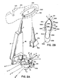
- Fig.1. is an isometric view showing portions of a machine that includes apparatus to apply an adhesive (cement) to the toe and ball region of a shoe (or other footwear) upper assembly;
- Fig. 2A is an isometric view of a portion of the machine in Fig. 1 showing a mechanical system to guide adhesive-applying nozzles in the machine of Fig.1;
- Fig. 2B is a plan view bottom up of two shoe upper assemblies to show the outline of the shoe upper assemblies of differing shoe size;
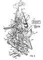
- Fig. 3 is an isometric view, like the view in Fig. 2A and partly sectioned, but showing further related machine parts; and
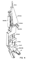
- Fig. 4 is an isometric view of the machine showing some parts not shown in other figures.
- Turning now to Fig.1, there is shown at 101 portions of a machine to apply adhesive or cement to the toe and ball region of the insole labelled 102 in Fig. 2B of a shoe ( or other footwear)
upper assembly 103 that includes a last 104 in Fig 2A, an upper 105 draped about the last andtheinsole 102 disposed at the bottom of the last 104. (It will be appreciated on the basis of this disclosure that the present invention can be applied to depositing adhesives to other parts of the footwear upper assembly, but toe and ball lasting are discussed mostly herein). According to the present teaching, and it is a most important aspect of the present invention, a mechanical structure is provided to guide the nozzles labelled 5 and 5A in Fig. 2B between the toe region marked 1 (where thenozzles upper assembly 103 to apply an adhesive as a ribbon - preferably onto the outer surface of theinsole 102 near the periphery thereof on both sides of the insole - from the toe region of the shoeupper assembly 103 to and including the ball region thereof. - The actual apparatus that applies the ribbon of adhesive onto the
insole 102 is generally shown at 107 in Fig.3 which includes most of the interacting structures used to perform the various functions in accordance with the present teaching. The function of theapparatus 107 is to apply anadhesive ribbon 109 and anadhesive ribbon 109A in Fig. 2B from thenozzles insole 102 of theupper assemblies upper assemblies upper assembly insoles nozzles insole 102 and the right side of theinsole 102, respectively, in Fig. 2B) at the toe region 1 of eitherassembly upper assembly 103A and thepaths upper assembly 103B. It is to provide a mostly mechanical guidance sysem for thenozzles ribbons sizes - It will be appreciated that the
mechanism 107 is part of a machine, for example, like that in the Vornberger patent, the adhesive extruding portions of the Vornberger patent being replaced by thenozzles structure 106 is needed here. The reaminder of this specification is directed mostly to themechanism 107 which is mostly mechanical structure whose function it is to direct the path of theadhesive nozzles insole 102 between the toe part thereof and the ball part thereof), whereby ribbons of molten adhesive are aplied onto theinsole 102, the margins of the upper 105 being thereafter wiped onto the insole in a known manner. (Conceptually, the adhesive can be applied onto the margin of the upper assembly, but preferably it is applied onto the outer surface of theinsole 102, near the edge or periphery of the insole). - The
apparatus 107 in Fig. 3 includes the pair ofadhesive nozzles insole 102 in Fig. 2B. A pair ofnozzle arms assemblies nozzle arms nozzles arm 17 is secured to and moves thenozzle 5 and thearm 17A is secured to and moves thenozzle 5A. Themechanical structure 107 is operable to properly guide thenozzles respective paths insole 102 to deposit a ribbon of adhesive onto theupper assembly 103 from the toe of the upper assembly to the ball region of the upper assembly. A brief discussion of Fig. 4 is made at this juncture. - The structures shown in Fig. 4 are the
right arm 17A with the further parts of theassembly 42A associated therewith. In Fig 4 the corresponding parts associated with thearm 17 are shown in parantheses, e.g. theair cylinder 39, the nozzles and so forth. In Fig. 4 thelabel 40A is for a shut-off needle valve; thelabel 43A (43) is for a feed tube of adhesive; thelabel 44A (44) is for an electrical conduit to a heater in theassembly 42A (42); thelabel 41A (41) is for an air cylinder to activate theneedle valve 40A (40); and thelabel 37 is for a pivot shaft, later discussed. Theneedle valve 40A (40) is moved up and down in Fig. 4 respectively to stop adhesive flow from thenozzle 5A (5) and to start flow therefrom. - In the shoemaking process, one approach is that of lasting the toe region of the shoe upper assembly first; then the ball and heel region are lasted. Typically the adhesive is applied onto the insole, which is disposed bottom down in a machine like that shown in the Vornberger patent, and the margin of the upper assembly is then wiped onto the insole. That is done according to the present teaching except that both the toe region and the ball region of the insole have adhesive applied thereto by two single-output nozzles and are wiped. The point made here is that, conceptually the adhesive could be applied to the margin of the upper assembly, rather than the insole, and the wiping could be effected, but application of adhesive as a ribbon on the insole is preferred, and either location comes within the characterisation that adhesive is applied in the region of the periphery of the insole.
- The single-
output nozzles nozzles nozzles cylinders stepper motor 18 in Fig.1 positions thenozzles cement paths arms nozzles shaft 37. Thearms countour template 2, formed of foursegments spring 48 in Fig. 3. It will be noted that thesegments template 2 which, when the segments are together, is, or can be, almost circular in plan view. However, the toe-end segments segments segments region 2‴ to some angle determined by the shoe size of the particular style. Further as is noted below, thesegments programmable controller 112 causes themotor 29 to start motion of thesegments segments - With reference now to Figs. 2A and 2B, the function of the contoured template or nozzle-
guide assembly 2 is to guide thefollowers 8 and 8A along appropriate paths so that thenozzles template segments particular template 2, and hence thesegments template segments - In operation the follwer 8 in Fig.,2A initially moves or rolls counterclockwise (see arrow 115) along the outer surface of the
template segment 6 and thefollower 8A moves or rolls clockwise (seearrow 115A) along the outer surface of thetemplate segment 6A; at an intermediate point the follower 8 rolls onto and along the outer surface of thetemplate segment 7 and thefollower 8A rolls onto and along the outer surface of thetemplate segment 7A. At that juncture typically, the followers will have completed the necessary travel on the small shoe size and to have appliedadhesive ribbons line 108 in Fig. 2B, that is, from the toe region to the ball region of the smallest shoe size of a given type. When applying adhesive ribbons onto theinsole 102 of shoe sizes larger than the smallest shoe size of a type, the template segments 6-7 and 6A-7A are caused to move in the direction of the arrows A or B or Aʹ or Bʹ, respectively, or any direction in between, as noted elsewhere herein. Thetemplate segments template segments followers 8 and 8A, in Fig. 2A are being moved along the outer perimeter surface of the corresponding segments or segment units 6-7 and 6A- 7A to move thenozzles appropriate line template segments segments segments nozzles guide assembly 2. - The mechanisms to move the
segments followers 8 and 8A are now discussed, mostly with reference to Figs 1 and 3, beginning with the followers. Thefollowers 8 and 8A are attached to thearms stepper motor 28 which is turned on and off by theprogrammable controller 112 which also controls the start of the adhesive extrusion and start of nozzle travel and control from beginning to end. When themotor 28 is energized it rotates the ballscrew marked 28A and hence moves aball nut 28B to the rightr and left in Fig.1; it pivots anarm 35B counterclockwise about ashaft 37 to which are keyedsleeves cement arms sleeves arms shaft 37 by forces originating with thefollowers 8 and 8A as the followers move along the template. The adhesive extrusion is stopped by signals fromsensors flags 21 and 21A; the same signals also start thenozzles arms template 2. - Movement of the template segments 6-7 and 6A-7A along the directions A... is similar to that discussed above with respect to the
followers 8 and 8A in thatstepper motor 19 rotates aball screw 29A and hence moves a ball nut 29B to the right and left in Fig.1, pivoting anarm 36B, again about theshaft 37 through asleeve 36 to which are attachedarms arms shaft 37. The segments are attached to thearms arms - A follower 14 in Fig. 3 is attached to the
arm 18 and alike follower 14A is attached to thearm 18A. The follower 14 follows along aguide bar 15 while, simultaneously thefollower 14A follows along aguide bar 15A. The guide bars 15 and 15A are adjustable either parallel to one another to provide motion A-Aʹ or at an angle to one another to provide motion B-Bʹ (or at any angle therebetween). Arack 16pinions rotary adjustment shaft 12. -
Air cylinder 10 and10A shift segments spring 43 causes the cam rolls 14 and 14A to remain in contact with the guide bars 15 and 15A. Aspring 48causes arms segments toe applications cylinders followers 8 and 8A to cause the followers to move along the template. - Pivoting at 2‴ is effected by two circular guide plates, e.g. a
guide plate 47A which pivots thesegments unit 6A-7A at 2‴ counterclockwise and clockwise in Fig.3. A like plate pivots thesegments pivot region 2‴ and can move away from one another during the linear or translational movement mentioned elsewhere herein. - It has been found for present purposes and on the basis of the teachings herein that a
segmented template 2 for any shoe style can be formed by a combination of graphical and triangulation methods known in the mechanical arts. Briefly, the rotational axis of therollers 8 and 8A are located in the machine with respect to theadhesive paths segmented template 2 and hence the path of travel of therollers 8 and 8A along the external contour of thetemplate 2. Variations in thepaths segments template 2 about the pivots 2ʹ, 2ʺ and 2‴, plus changes in the angles A to B and Aʹ to Bʹ and changes in segment size. - Turning now to Fig. 1, a
rod 13 connects to a heel-lock assembly (not shown) whereby the shoe size is established. If therod 13 is all the way to the right in Fig. 1, a small shoe is indicated. The rod 123 is attached to a sensor-cam mounting plate 19 that is journalled to theshaft 37; theplate 19supports sensor cams roller 46 and aroller 34, respectively, Asensor 24 pivots about ashaft 30 under control of theroller 46 to establish the stop point for the motion of the templates along the paths whose directions are A and B or Aʹ or Bʹ or any angle therebetween; start of that motion is determined by asensor 27 in Fig.1 in co-operation with asensor flag 26 which moves left and right with rotation of therod 28A to which it is attached. Thesensor 24 similarly co-operates with aflag 25 which is attached to thearm 31 which is attached to thesleeve 36 which, as above-noted is moved by themotor 29. - The
motor 28 at all times give maximum travel to thearms air cylinder appropriate stop point needle 40A (40) upward to terminate adhesive flow from thenozzle 5A (5). The signal for such purpose comes from thesensors flags 21 and 21A which are positioned by thesensor cam 32. Acam roll 34 is attached to anarm 33 which holds theflags 21 and 21A which are shiftable up or down (see arrow 47) byair cylinders - Modifications of the invention herein disclosed will occur to persons skilled in the art and all such modifications are deemed to be within the scope of the invention as defined by the appended claims.
Claims (14)
a pair of adhesive nozzles (5, 5A) to apply the adhesive onto the footwear upper assembly (103) near the edge of the insole (102);
a pair of nozzle arms, (17, 17A) one nozzle arm of the pair of nozzle arms being secured to each nozzle of the pair of adhesive nozzles (5, 5A) and adapted to move the nozzle secured thereto;
a mechanical structure (107) operable to guide the nozzles (5, 5A) along respective paths adjacent each edge of the insole (102) to deposit a ribbon of adhesive (109) onto the upper assembly (103) from the toe of the upper assembly to the ball region of the upper assembly (103), said mechanical structure (107) compromising a nozzle-guide template (2) that is configured to an outline that, together with other mechanical structures, matches the outline of the insole (102) between the toe and the ball region of the smallest upper assembly (103) of the style to be lasted, the nozzle-guide template (2) having a guide surface and being shiftable to accommodate right footwear upper assemblies and left footwear upper assemblies of the style to be lasted, said nozzle-guide template (2) comprising a pair of nozzle-guide segments (6,7,6A,7A) individually pivotally connected at the toe region thereof to permit angular adjustment of the one segment of the pair of segments relative to the other to match the shape of the insole (102) for footwear sizes larger than the smallest footwear upper assembly (103) ;
a template follower (8,8A) connected to each nozzle arm (17,17A) one follower being positioned to ride along the guide surface of each nozzle-guide template (2); and
drive means (28,29) operable to move the template follower (8,8A) from the toe region of its associated nozzle-guide template (2) to the ball region thereof.
said structure (107) being operable to guide the nozzle means (5, 5A) along a path adjacent each edge of the insole (102) to deposit an adhesive ribbon (109) onto the upper assembly (103) and comprising a nozzle-guide template (2) having a guide surface that is configured to an outline that, together with other mechanical structures that interact therewith, matches the outline of the insole (102) of the portion to be lasted of the upper assembly (103) of the style to be lasted, the nozzle-guide template (2) being shiftable to accommodate at least one of different shaped and sized upper assemblies, said nozzle-guide template (2) comprising segments (6, 7, 6A, 7A) having a toe region and being individually pivotally connected at the toe region thereof to permit angular adjustment of each segment relative to the other to match at least one of each shape and size of the insole (102) of the footwear upper assembly (103);
a template follower (8, 8A) connected to ride along the guide surface of each nozzle-guide segment (6,7,6A,7A) and adapted to guide the nozzle means (5,5A); and
drive means (28,29) operable to move the template follower (8,8A) along said guide surface.
adhesive nozzle means (5,5A) to apply the adhesive onto the footwear upper assembly (103) near the edge of the insole (102);
nozzle arms means (17,17A) secured to the adhesive nozzle means (5,5A) and adapted to move the adhesive nozzle means (5,5A) secured thereto;
a structure (107) operable to guide the nozzles along respective paths adhacent each edge of the insole (102)to deposit a ribbon of adhesive (109) onto the upper assembly, said structure (107) comprising a nozzle-guide template (2) that is configured to an outline that, together with other mechanical structures, matches the outline of the insole (102) of the portion to be lasted of the smallest upper assembly (103) of the style to be lasted, the nozzle-guide template (2) having a guide surface and being shiftable to accommodate different shaped upper assemblies, said nozzle-guide template (2) comprising segments (6,7,6A,7A) pivotably connected at the toe region thereof to permit angular adjustment of each segment relative to the other to match the shape of the insole (102) for footwear sizes larger than the smallest footwear upper assembly (103);
a template follower (8,8A) connected to each nozzle arm (17,17A), one follower being positioned to ride along the guide surface of each nozzle-guide segment (6,7,6A,7A); and
drive means (28,29) operable to move the template follower along said guide surface.
providing a structure (107) operable to guide a pair of adhesive nozzles (5,5A) along respective paths adjacent each edge of the insole (102) to deposit an adhesive onto the upper assembly (103), said structure comprising a nozzle-guide template (2) that is configured to an outline that, together with other mechanical structures that itneract therewith,matches the outline of a portion of the insole (102), to be lasted, the nozzle-guide template (2) having a guide surface and being shiftable at the toe region thereof to accommodate different-shaped upper assemblies (103), said nozzle-guide template (2) comprising a first pair of nozzle-guide segments (6,7,6A,7A) individually pivotally conected at the toe region thereof to permit angular adjustment of each segment relative to the other to match, when interacting with said other mechanical structures, the shape of the insole (102);
Providing a pair of nozzles (5,5A) to apply the adhesive in onto the footwear upper assembly (103) near the edge of the insole (102);
providing a pair of template followers (8,8A), one template follower (8,8A) being positioned to ride along the guide surface of a nozzle-guide segment (6,7,6A,7A) and being connected to one nozzle (5,5A) of the pair of nozzles; and
moving each template follower (8,8A) along the guide surface of its associated nozzle-guide segment (6,7,6A,7A) to guide the respective nozzle (5,5A) along the upper assembly (103) adjacent the region of adhesive deposition.
Applications Claiming Priority (2)
| Application Number | Priority Date | Filing Date | Title |
|---|---|---|---|
| US94408586A | 1986-12-22 | 1986-12-22 | |
| US944085 | 1986-12-22 |
Publications (3)
| Publication Number | Publication Date |
|---|---|
| EP0273672A2 true EP0273672A2 (en) | 1988-07-06 |
| EP0273672A3 EP0273672A3 (en) | 1989-07-12 |
| EP0273672B1 EP0273672B1 (en) | 1992-05-27 |
Family
ID=25480760
Family Applications (1)
| Application Number | Title | Priority Date | Filing Date |
|---|---|---|---|
| EP19870311263 Expired EP0273672B1 (en) | 1986-12-22 | 1987-12-21 | Toe and ball laster |
Country Status (3)
| Country | Link |
|---|---|
| EP (1) | EP0273672B1 (en) |
| CA (1) | CA1290510C (en) |
| DE (1) | DE3779413D1 (en) |
Cited By (2)
| Publication number | Priority date | Publication date | Assignee | Title |
|---|---|---|---|---|
| EP0403231A2 (en) * | 1989-06-13 | 1990-12-19 | International Shoe Machine Corporation | Heel laster |
| EP0514349A1 (en) * | 1991-05-08 | 1992-11-19 | ORMAC S.p.A. | Glue dispensing device |
Citations (5)
| Publication number | Priority date | Publication date | Assignee | Title |
|---|---|---|---|---|
| US2008801A (en) * | 1933-02-07 | 1935-07-23 | United Shoe Machinery Corp | Cementing machine |
| GB1134070A (en) * | 1965-06-30 | 1968-11-20 | Zd Y Presneho Strojirenstvi Go | A method of and an apparatus for applying thermo-reactive-adhesive to the insoles of shoes |
| FR2198362A5 (en) * | 1972-09-01 | 1974-03-29 | Huber Et Cie Sa L Ets | |
| FR2225114A1 (en) * | 1973-04-13 | 1974-11-08 | Usm Corp | |
| DE3341118C1 (en) * | 1983-11-12 | 1984-08-16 | Internationale Schuh-Maschinen Co Gmbh, 6780 Pirmasens | Process and apparatus for the application of flowable adhesive, especially to the insole and/or the lasting edge, projecting above the insole, of a shoe unit |
-
1987
- 1987-12-21 EP EP19870311263 patent/EP0273672B1/en not_active Expired
- 1987-12-21 CA CA000554960A patent/CA1290510C/en not_active Expired - Fee Related
- 1987-12-21 DE DE8787311263T patent/DE3779413D1/en not_active Expired - Lifetime
Patent Citations (5)
| Publication number | Priority date | Publication date | Assignee | Title |
|---|---|---|---|---|
| US2008801A (en) * | 1933-02-07 | 1935-07-23 | United Shoe Machinery Corp | Cementing machine |
| GB1134070A (en) * | 1965-06-30 | 1968-11-20 | Zd Y Presneho Strojirenstvi Go | A method of and an apparatus for applying thermo-reactive-adhesive to the insoles of shoes |
| FR2198362A5 (en) * | 1972-09-01 | 1974-03-29 | Huber Et Cie Sa L Ets | |
| FR2225114A1 (en) * | 1973-04-13 | 1974-11-08 | Usm Corp | |
| DE3341118C1 (en) * | 1983-11-12 | 1984-08-16 | Internationale Schuh-Maschinen Co Gmbh, 6780 Pirmasens | Process and apparatus for the application of flowable adhesive, especially to the insole and/or the lasting edge, projecting above the insole, of a shoe unit |
Cited By (3)
| Publication number | Priority date | Publication date | Assignee | Title |
|---|---|---|---|---|
| EP0403231A2 (en) * | 1989-06-13 | 1990-12-19 | International Shoe Machine Corporation | Heel laster |
| EP0403231A3 (en) * | 1989-06-13 | 1993-01-13 | International Shoe Machine Corporation | Heel laster |
| EP0514349A1 (en) * | 1991-05-08 | 1992-11-19 | ORMAC S.p.A. | Glue dispensing device |
Also Published As
| Publication number | Publication date |
|---|---|
| CA1290510C (en) | 1991-10-15 |
| EP0273672B1 (en) | 1992-05-27 |
| DE3779413D1 (en) | 1992-07-02 |
| EP0273672A3 (en) | 1989-07-12 |
Similar Documents
| Publication | Publication Date | Title |
|---|---|---|
| EP0344400B1 (en) | Suit material support device | |
| US3963840A (en) | Cement lasting the side and heel portions of a shoe assembly | |
| CA1329969C (en) | Roughing machine for footwear upper assemblies and a system that includes the roughing machine but typically includes as well other machines ahead of and following | |
| CA1308220C (en) | Multi-station system to act upon footwear upper assemblies with transfer between stations thereof | |
| EP0403231B1 (en) | Heel laster | |
| EP0273672B1 (en) | Toe and ball laster | |
| US4829932A (en) | Toe and ball laster and the like | |
| US3591878A (en) | Shoe lasting machines | |
| CA1259762A (en) | Side and heel lasting machine | |
| EP0113192A2 (en) | A device for toe and ball lasting of a shoe unit | |
| US4679269A (en) | Heel lasting machine | |
| US4480581A (en) | Deposition apparatus | |
| EP0339796B1 (en) | Heel molder | |
| EP0138474A2 (en) | Adhesive applicator | |
| US3868737A (en) | Method and apparatus for combined lasting of the toe, ball and shank areas of shoes | |
| US4095302A (en) | Manufacture of shoes | |
| EP0162696B1 (en) | Side and heel lasting machine | |
| KR970002514B1 (en) | Wiper assembly for shoe lasting machine | |
| EP0271303B1 (en) | Machine for lasting side portions of shoe uppers | |
| US3803654A (en) | Lasting machine | |
| US5263216A (en) | Machine for lasting side and heel seat portions of shoes | |
| EP0330982A2 (en) | Machine for lasting side portions of shoes | |
| EP0655207A1 (en) | Automatic machine for the controlled roughening of the edge of an upper | |
| CA1153166A (en) | Shoe lasting machine | |
| US5153961A (en) | Apparatus to close, stretch and nail the flanks of a shoe vamp to a respective insole, in particular in machine for assembling shoe parts |
Legal Events
| Date | Code | Title | Description |
|---|---|---|---|
| PUAI | Public reference made under article 153(3) epc to a published international application that has entered the european phase |
Free format text: ORIGINAL CODE: 0009012 |
|
| AK | Designated contracting states |
Kind code of ref document: A2 Designated state(s): DE FR GB IT |
|
| PUAL | Search report despatched |
Free format text: ORIGINAL CODE: 0009013 |
|
| AK | Designated contracting states |
Kind code of ref document: A3 Designated state(s): DE FR GB IT |
|
| 17P | Request for examination filed |
Effective date: 19890918 |
|
| 17Q | First examination report despatched |
Effective date: 19910214 |
|
| GRAA | (expected) grant |
Free format text: ORIGINAL CODE: 0009210 |
|
| ITF | It: translation for a ep patent filed | ||
| AK | Designated contracting states |
Kind code of ref document: B1 Designated state(s): DE FR GB IT |
|
| REF | Corresponds to: |
Ref document number: 3779413 Country of ref document: DE Date of ref document: 19920702 |
|
| ET | Fr: translation filed | ||
| PLBE | No opposition filed within time limit |
Free format text: ORIGINAL CODE: 0009261 |
|
| STAA | Information on the status of an ep patent application or granted ep patent |
Free format text: STATUS: NO OPPOSITION FILED WITHIN TIME LIMIT |
|
| 26N | No opposition filed | ||
| PGFP | Annual fee paid to national office [announced via postgrant information from national office to epo] |
Ref country code: FR Payment date: 19961230 Year of fee payment: 10 |
|
| PGFP | Annual fee paid to national office [announced via postgrant information from national office to epo] |
Ref country code: DE Payment date: 19970615 Year of fee payment: 10 |
|
| PG25 | Lapsed in a contracting state [announced via postgrant information from national office to epo] |
Ref country code: FR Free format text: THE PATENT HAS BEEN ANNULLED BY A DECISION OF A NATIONAL AUTHORITY Effective date: 19971231 |
|
| PGFP | Annual fee paid to national office [announced via postgrant information from national office to epo] |
Ref country code: GB Payment date: 19980217 Year of fee payment: 11 |
|
| PG25 | Lapsed in a contracting state [announced via postgrant information from national office to epo] |
Ref country code: DE Free format text: LAPSE BECAUSE OF NON-PAYMENT OF DUE FEES Effective date: 19980901 |
|
| REG | Reference to a national code |
Ref country code: FR Ref legal event code: ST |
|
| PG25 | Lapsed in a contracting state [announced via postgrant information from national office to epo] |
Ref country code: GB Free format text: LAPSE BECAUSE OF NON-PAYMENT OF DUE FEES Effective date: 19981221 |
|
| GBPC | Gb: european patent ceased through non-payment of renewal fee |
Effective date: 19981221 |
|
| PG25 | Lapsed in a contracting state [announced via postgrant information from national office to epo] |
Ref country code: IT Free format text: LAPSE BECAUSE OF NON-PAYMENT OF DUE FEES;WARNING: LAPSES OF ITALIAN PATENTS WITH EFFECTIVE DATE BEFORE 2007 MAY HAVE OCCURRED AT ANY TIME BEFORE 2007. THE CORRECT EFFECTIVE DATE MAY BE DIFFERENT FROM THE ONE RECORDED. Effective date: 20051221 |