EP0273525A2 - Device for supporting the fuel charging filler for motor vehicles - Google Patents
Device for supporting the fuel charging filler for motor vehicles Download PDFInfo
- Publication number
- EP0273525A2 EP0273525A2 EP87202574A EP87202574A EP0273525A2 EP 0273525 A2 EP0273525 A2 EP 0273525A2 EP 87202574 A EP87202574 A EP 87202574A EP 87202574 A EP87202574 A EP 87202574A EP 0273525 A2 EP0273525 A2 EP 0273525A2
- Authority
- EP
- European Patent Office
- Prior art keywords
- container
- door
- filler
- bodywork
- supporting
- Prior art date
- Legal status (The legal status is an assumption and is not a legal conclusion. Google has not performed a legal analysis and makes no representation as to the accuracy of the status listed.)
- Granted
Links
Images


Classifications
-
- B—PERFORMING OPERATIONS; TRANSPORTING
- B60—VEHICLES IN GENERAL
- B60K—ARRANGEMENT OR MOUNTING OF PROPULSION UNITS OR OF TRANSMISSIONS IN VEHICLES; ARRANGEMENT OR MOUNTING OF PLURAL DIVERSE PRIME-MOVERS IN VEHICLES; AUXILIARY DRIVES FOR VEHICLES; INSTRUMENTATION OR DASHBOARDS FOR VEHICLES; ARRANGEMENTS IN CONNECTION WITH COOLING, AIR INTAKE, GAS EXHAUST OR FUEL SUPPLY OF PROPULSION UNITS IN VEHICLES
- B60K15/00—Arrangement in connection with fuel supply of combustion engines or other fuel consuming energy converters, e.g. fuel cells; Mounting or construction of fuel tanks
- B60K15/03—Fuel tanks
- B60K15/04—Tank inlets
- B60K15/05—Inlet covers
-
- E—FIXED CONSTRUCTIONS
- E05—LOCKS; KEYS; WINDOW OR DOOR FITTINGS; SAFES
- E05B—LOCKS; ACCESSORIES THEREFOR; HANDCUFFS
- E05B83/00—Vehicle locks specially adapted for particular types of wing or vehicle
- E05B83/28—Locks for glove compartments, console boxes, fuel inlet covers or the like
- E05B83/34—Locks for glove compartments, console boxes, fuel inlet covers or the like for fuel inlet covers essentially flush with the vehicle surface
-
- B—PERFORMING OPERATIONS; TRANSPORTING
- B60—VEHICLES IN GENERAL
- B60K—ARRANGEMENT OR MOUNTING OF PROPULSION UNITS OR OF TRANSMISSIONS IN VEHICLES; ARRANGEMENT OR MOUNTING OF PLURAL DIVERSE PRIME-MOVERS IN VEHICLES; AUXILIARY DRIVES FOR VEHICLES; INSTRUMENTATION OR DASHBOARDS FOR VEHICLES; ARRANGEMENTS IN CONNECTION WITH COOLING, AIR INTAKE, GAS EXHAUST OR FUEL SUPPLY OF PROPULSION UNITS IN VEHICLES
- B60K15/00—Arrangement in connection with fuel supply of combustion engines or other fuel consuming energy converters, e.g. fuel cells; Mounting or construction of fuel tanks
- B60K15/03—Fuel tanks
- B60K15/04—Tank inlets
- B60K15/0406—Filler caps for fuel tanks
- B60K2015/0419—Self-sealing closure caps, e.g. that don't have to be removed manually
-
- B—PERFORMING OPERATIONS; TRANSPORTING
- B60—VEHICLES IN GENERAL
- B60K—ARRANGEMENT OR MOUNTING OF PROPULSION UNITS OR OF TRANSMISSIONS IN VEHICLES; ARRANGEMENT OR MOUNTING OF PLURAL DIVERSE PRIME-MOVERS IN VEHICLES; AUXILIARY DRIVES FOR VEHICLES; INSTRUMENTATION OR DASHBOARDS FOR VEHICLES; ARRANGEMENTS IN CONNECTION WITH COOLING, AIR INTAKE, GAS EXHAUST OR FUEL SUPPLY OF PROPULSION UNITS IN VEHICLES
- B60K15/00—Arrangement in connection with fuel supply of combustion engines or other fuel consuming energy converters, e.g. fuel cells; Mounting or construction of fuel tanks
- B60K15/03—Fuel tanks
- B60K15/04—Tank inlets
- B60K15/05—Inlet covers
- B60K2015/0561—Locking means for the inlet cover
- B60K2015/0576—Locking means for the inlet cover with actuator fixed to the vehicle body
-
- E—FIXED CONSTRUCTIONS
- E05—LOCKS; KEYS; WINDOW OR DOOR FITTINGS; SAFES
- E05B—LOCKS; ACCESSORIES THEREFOR; HANDCUFFS
- E05B47/00—Operating or controlling locks or other fastening devices by electric or magnetic means
- E05B47/02—Movement of the bolt by electromagnetic means; Adaptation of locks, latches, or parts thereof, for movement of the bolt by electromagnetic means
-
- Y—GENERAL TAGGING OF NEW TECHNOLOGICAL DEVELOPMENTS; GENERAL TAGGING OF CROSS-SECTIONAL TECHNOLOGIES SPANNING OVER SEVERAL SECTIONS OF THE IPC; TECHNICAL SUBJECTS COVERED BY FORMER USPC CROSS-REFERENCE ART COLLECTIONS [XRACs] AND DIGESTS
- Y10—TECHNICAL SUBJECTS COVERED BY FORMER USPC
- Y10T—TECHNICAL SUBJECTS COVERED BY FORMER US CLASSIFICATION
- Y10T403/00—Joints and connections
- Y10T403/16—Joints and connections with adjunctive protector, broken parts retainer, repair, assembly or disassembly feature
- Y10T403/1616—Position or guide means
- Y10T403/1624—Related to joint component
-
- Y—GENERAL TAGGING OF NEW TECHNOLOGICAL DEVELOPMENTS; GENERAL TAGGING OF CROSS-SECTIONAL TECHNOLOGIES SPANNING OVER SEVERAL SECTIONS OF THE IPC; TECHNICAL SUBJECTS COVERED BY FORMER USPC CROSS-REFERENCE ART COLLECTIONS [XRACs] AND DIGESTS
- Y10—TECHNICAL SUBJECTS COVERED BY FORMER USPC
- Y10T—TECHNICAL SUBJECTS COVERED BY FORMER US CLASSIFICATION
- Y10T70/00—Locks
- Y10T70/50—Special application
- Y10T70/5093—For closures
- Y10T70/554—Cover, lid, cap, encasing shield
- Y10T70/5544—Pivoted
Definitions
- the metal sheet is furthermore indicated, of the bodywork, to which the filler support device is fastened, e.g., adhesive-bonded, in such a way that the door 11 comes to be in correspondence of an opening 52A of the metal sheet 42 of the bodywork of the motor vehicle, with the container 10 being complete, equipped with the door and the electrical door actuator.
Landscapes
- Engineering & Computer Science (AREA)
- Life Sciences & Earth Sciences (AREA)
- Sustainable Development (AREA)
- Sustainable Energy (AREA)
- Chemical & Material Sciences (AREA)
- Combustion & Propulsion (AREA)
- Transportation (AREA)
- Mechanical Engineering (AREA)
- Cooling, Air Intake And Gas Exhaust, And Fuel Tank Arrangements In Propulsion Units (AREA)
Abstract
Description
- The present invention relates to a support device for the fuel charging filler for motor vehicles.
- It is known that the motor vehicles are generally equipped with a device for fuel charging, located on the outer skin of the rear side portion of the bodywork, and formed by a metal part, or a rubber part, which defines a housing for the fuel filler and for the relating sealing cap, and is welded, or otherways fastened, to the metal sheet of the bodywork in correspondence of an opening provided on the same bodywork. Due to aesthetical and aerodynamic reasons, the filler sealing caps are covered, or masked, with a door, which, in most cases, is directly hinged to an edge provided on the metal sheet of the same bodywork.
- It is clear that during the step of assemblage of the filler, and of the relevant covering door, a number of interventions are necessary, which must be carried out directly on the same bodywork, and it is known as well that such a type of interventions, by the assembler, are rather critical, due to reasons of available room.
- The purpose of the present invention is to propose a device for supporting the fuel charging filler, whose assemblage on the bodywork of a motor vehicle results extremely simplified.
- In order to achieve this purpose, according to the invention a device is proposed, for supporting the fuel charging filler for motor vehicles, which comprises a filler support part, defining a housing for the filler, and shaped to be fastened to the metal sheet of the bodywork of the motor vehicle, in correspondence of an opening provided on the same bodywork, the device being characterized in that is it constituted by an integrated unit, comprising a container element having an opening for housing the filler, a door hinged onto the container element, and undergoing the action of elastic opening means, and electrically actuatable locking means for the door, the container element with the door, and the locking means mounted on it being suitable for being fastened to the metal sheet of the bodywork.
- Advantageously, the above said container can be made as one single piece only, e.g., of plastics material, substantially formed by a cup-shaped body, with an opening for housing the filler, in said container also opposite seats being provided, which are constituted by cylindrical hollows suitable for supporting the pivots linking the door to the container.
- Simple and rapid is furthermore a preferred hinging system, for hinging the door to the container, accomplished by means of two pivots, with the interposition of a cylindrical spring, said pivots and said spring being housed, coaxial, inside a cylindrical through bore provided on the same door, said pivots being supported inside the seats provided on the container, and the seats being provided each with an invitation slot for the assemblage of the pivots.
- The container can be also equipped with a bracket, integrally realized as one single piece with the cup-shaped body, to make it possible the electrical actuator for the above said door-locking means to be fastened.
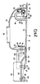
- The advantages and characteristics of the present invention are now illustrated by referring to the hereto attached Figures 1, 2 and 3, wherein, as a non-limitative example, a preferred practical embodiment of the same invention is shown.
- Figure 1 shows a plan view of a support device according to the present invention, wherein the hinging of the door to the container body is also visible.
- Figure 2 shows a sectional view according to path II-II of Figure 1.
- Figure 3 shows an enlarged sectional view according to path III-III of Figure 2.
- In Figures 1, 2 and 3, by the
reference numeral 10 the container for the filler (with the relevant cap), not shown in the figures, is generally indicated, and by thereference numeral 11 generally indicated is the sealing door, with said sealingdoor 11 being constituted by aplate 12 of a substantially circular shape, provided, on the side of itsinternal surface 13, with aprotruding edge 14, wherein acountersunk bore 15 is provided, which is suitable for receiving alocking latch 50 of anelectrical actuator 51. - In a position diametrically opposite to the
edge 14, thedoor 11 is provided with an "U"-shaped arm 16, which forms one single piece with theplate 12, and whosefree end 17 is provided with athrough bore 19, extending parallelly to the curvature of the "U". By thenumeral 20, indicated is a hollow, provided on theend 17, parallelly to thethrough bore 19, and by thenumerals bore 46 and, respectively, 47, suitable for receiving arespective peg spring 23, located between thepivots through bore 19, axially urges thepivots cylindrical seats container 10, suitable for rotatably receiving thepivots reference numerals pivots cylindrical seats cylindrical spring 18, acting in the direction of opening of thedoor 11, has a central portion which engages the "U"-shaped portion 16 of thedoor 11, andrespective ends container 10 inside hollows, respectively indicated by thereference numerals - Inside the interior portion of the
container 10, astop bracket 32 for thedoor 11 is shaped, which is provided with anelastic stop 45 destined to come into engagement with the free end of theedge 14, and by thereference numeral 35 an opening of substantially circular shape is indicated, which is destined to receive the fuel charging pipe, not shown in the figures. - The
container 10 is furthermore provided, at the side opposite to the side on which thedoor 11 is hinged, with abracket 36, on which there areprotrusions bores electrical actuator 51 by means of fasteningscrews reference numerals bracket 36 are indicated, and by 41 a bore incontainer 10 is indicated, to allow the passage of thelocking latch 50. - In Figure 2, by 42 the metal sheet is furthermore indicated, of the bodywork, to which the filler support device is fastened, e.g., adhesive-bonded, in such a way that the
door 11 comes to be in correspondence of an opening 52A of themetal sheet 42 of the bodywork of the motor vehicle, with thecontainer 10 being complete, equipped with the door and the electrical door actuator. - In order to open the
door 11, theelectrical actuator 51 is energized, and moves thelatch 50 towards itself, as shown by the dashed line 50ʹ; as soon as thedoor 50 has left the countersunk bore 15, thespring 18 urges thedoor 11 outwards; in the meantime, theactuator 51, de-energized, makes thelatch 50 return back to its initial position. To shut thedoor 11 again, it is enough to push it, up to overcome the force of a spring, not shown, which counteracts the rearwards motion of thelatch 50.
Claims (6)
Applications Claiming Priority (2)
| Application Number | Priority Date | Filing Date | Title |
|---|---|---|---|
| IT2426486U | 1986-12-30 | ||
| IT2426486U IT213495Z2 (en) | 1986-12-30 | 1986-12-30 | SUPPORT DEVICE FOR THE FUEL INDUCTION OF FUEL FOR MOTOR VEHICLES. |
Publications (3)
| Publication Number | Publication Date |
|---|---|
| EP0273525A2 true EP0273525A2 (en) | 1988-07-06 |
| EP0273525A3 EP0273525A3 (en) | 1988-12-14 |
| EP0273525B1 EP0273525B1 (en) | 1991-02-27 |
Family
ID=11212820
Family Applications (1)
| Application Number | Title | Priority Date | Filing Date |
|---|---|---|---|
| EP19870202574 Expired - Lifetime EP0273525B1 (en) | 1986-12-30 | 1987-12-18 | Device for supporting the fuel charging filler for motor vehicles |
Country Status (5)
| Country | Link |
|---|---|
| US (1) | US4917404A (en) |
| EP (1) | EP0273525B1 (en) |
| DE (1) | DE3768234D1 (en) |
| ES (1) | ES2021352B3 (en) |
| IT (1) | IT213495Z2 (en) |
Cited By (3)
| Publication number | Priority date | Publication date | Assignee | Title |
|---|---|---|---|---|
| EP0760306A1 (en) * | 1995-12-01 | 1997-03-05 | OMEGAL (Société Anonyme) | Tank inlet cover |
| EP1571029A3 (en) * | 2004-03-03 | 2006-10-04 | ITW Automotive Products GmbH & Co. KG | Fuel door housing for automobiles |
| CN107882443A (en) * | 2016-09-30 | 2018-04-06 | 比亚迪股份有限公司 | The tripper and vehicle of charging port cap |
Families Citing this family (15)
| Publication number | Priority date | Publication date | Assignee | Title |
|---|---|---|---|---|
| KR0114066Y1 (en) * | 1994-08-23 | 1998-04-11 | Hyundai Motor Co Ltd | Fuel filler door catch for a motor vehicle |
| IT1289824B1 (en) * | 1996-12-31 | 1998-10-16 | Itw Fastex Italia Spa | FUEL REFUELER ASSEMBLY, ESPECIALLY FOR A MOTOR VEHICLE. |
| FR2761935B1 (en) * | 1997-04-14 | 1999-05-14 | Journee Paul Sa | DEVICE FOR FILLING A FUEL TANK FOR A MOTOR VEHICLE COMPRISING IMPROVED MEANS FOR LOCKING A SHUTTER SHUTTER |
| USD398280S (en) | 1997-05-08 | 1998-09-15 | William Home | Overfill protection unit |
| EP0958956B1 (en) * | 1998-05-23 | 2001-11-21 | Ford Global Technologies, Inc., A subsidiary of Ford Motor Company | Remote release for a tank filler spout inlet cover for passenger cars |
| TW448262B (en) * | 1999-08-02 | 2001-08-01 | Takigen Mfg Co | Lockable cap |
| ITTO20060151A1 (en) * | 2006-03-01 | 2007-09-02 | Fiat Auto Spa | DOOR GROUP FOR THE FUEL TANK OF THE FUEL TANK OF A MOTOR VEHICLE. |
| US20070215240A1 (en) * | 2006-03-01 | 2007-09-20 | Stant Manufacturing Inc. | Lockable barricade for capless fuel tank filler neck |
| US8162375B2 (en) * | 2008-01-25 | 2012-04-24 | Illinois Tool Works Inc. | Hinge mounted fuel housing seal |
| BRPI0908852A2 (en) * | 2008-02-22 | 2019-03-06 | Honda Motor Co Ltd | cap structure for opening the vehicle fuel filler tube |
| KR101382281B1 (en) * | 2011-12-09 | 2014-04-09 | 현대자동차(주) | Fuel door apparatus of vehicle |
| CN103879462B (en) * | 2014-03-20 | 2016-02-03 | 青岛环球集团股份有限公司 | A kind of spring loaded oil filling port wicket of heavy duty truck fuel tank |
| JP6949630B2 (en) * | 2017-09-05 | 2021-10-13 | 株式会社アイシン | Lid lock device for vehicles |
| JP7055069B2 (en) * | 2018-06-14 | 2022-04-15 | 株式会社Fts | How to attach the lid |
| DE102019119091B4 (en) * | 2019-07-15 | 2022-02-10 | Illinois Tool Works Inc. | LOADER OR TANK HOUSING AND METHOD OF MANUFACTURE THEREOF |
Family Cites Families (13)
| Publication number | Priority date | Publication date | Assignee | Title |
|---|---|---|---|---|
| US2035895A (en) * | 1935-03-01 | 1936-03-31 | J F Goetz | Vehicle closure and operating means therefor |
| US2081717A (en) * | 1936-04-21 | 1937-05-25 | Harry C Steele | Tank closure |
| US2259970A (en) * | 1940-06-21 | 1941-10-21 | Nash Kelvinator Corp | Hinge |
| US3334779A (en) * | 1965-09-09 | 1967-08-08 | Richard N Smith | Closure for automotive fuel tanks and the like |
| ES393588A1 (en) * | 1970-07-15 | 1974-10-01 | Des Brevets Neiman Soc D Expl | REMOTE CONTROL SYSTEM FOR THE CAP OF A FUEL TANK. |
| EP0030531A3 (en) * | 1978-07-13 | 1981-07-22 | Bossert Kg | Flap device for a vehicle |
| DE2852855C2 (en) * | 1978-12-07 | 1984-04-12 | Ford-Werke AG, 5000 Köln | Closure flap for covering a body opening of a motor vehicle |
| FR2474575A1 (en) * | 1980-01-24 | 1981-07-31 | Peugeot | Car petrol filler flap locking - has latch which can be released manually or by central locking |
| JPS58180320A (en) * | 1982-04-15 | 1983-10-21 | Nissan Motor Co Ltd | Burglarproof construction of fuel filler lid |
| DE3301072C3 (en) * | 1983-01-14 | 1997-11-20 | Itw Ateco Gmbh | Tank well for motor vehicles |
| JPS61139518A (en) * | 1984-12-13 | 1986-06-26 | Nissan Motor Co Ltd | Structure around fuel feed port of car |
| JPS61163019A (en) * | 1985-01-11 | 1986-07-23 | Nissan Motor Co Ltd | Fuel filler lid hinge device |
| JPS61285123A (en) * | 1985-06-10 | 1986-12-15 | Nissan Shatai Co Ltd | Filler cap device |
-
1986
- 1986-12-30 IT IT2426486U patent/IT213495Z2/en active
-
1987
- 1987-12-16 US US07/133,878 patent/US4917404A/en not_active Expired - Fee Related
- 1987-12-18 EP EP19870202574 patent/EP0273525B1/en not_active Expired - Lifetime
- 1987-12-18 DE DE8787202574T patent/DE3768234D1/en not_active Expired - Fee Related
- 1987-12-18 ES ES87202574T patent/ES2021352B3/en not_active Expired - Lifetime
Cited By (4)
| Publication number | Priority date | Publication date | Assignee | Title |
|---|---|---|---|---|
| EP0760306A1 (en) * | 1995-12-01 | 1997-03-05 | OMEGAL (Société Anonyme) | Tank inlet cover |
| EP1571029A3 (en) * | 2004-03-03 | 2006-10-04 | ITW Automotive Products GmbH & Co. KG | Fuel door housing for automobiles |
| US7185938B2 (en) | 2004-03-03 | 2007-03-06 | Itw Automotive Products Gmbh & Co. Kg | Fuel door housing for automobiles |
| CN107882443A (en) * | 2016-09-30 | 2018-04-06 | 比亚迪股份有限公司 | The tripper and vehicle of charging port cap |
Also Published As
| Publication number | Publication date |
|---|---|
| US4917404A (en) | 1990-04-17 |
| IT8624264V0 (en) | 1986-12-30 |
| DE3768234D1 (en) | 1991-04-04 |
| EP0273525A3 (en) | 1988-12-14 |
| IT213495Z2 (en) | 1990-01-18 |
| ES2021352B3 (en) | 1991-11-01 |
| EP0273525B1 (en) | 1991-02-27 |
Similar Documents
| Publication | Publication Date | Title |
|---|---|---|
| US4917404A (en) | Device for supporting the fuel charging filler for motor vehicles | |
| US4789232A (en) | Break-away pivot system for rearview mirrors | |
| US4944540A (en) | Sliding radiator grill | |
| US7380861B2 (en) | Plastic fuel inlet compartment | |
| US4958877A (en) | Composite pivot bushing and cover for vehicle seat hinge bracket | |
| EP0718134B1 (en) | A hatch back door structure for motor vehicles | |
| CA2173275A1 (en) | Fuel filler door actuator assembly with integral kick-out spring | |
| US6371537B1 (en) | Electric lock casing for an automobile vehicle boot closure member | |
| EP0999325A2 (en) | Vehicle door handle | |
| KR20110033817A (en) | Vehicle Locking Mechanism | |
| KR20110038603A (en) | Vehicle Locking Mechanism | |
| CN102597392A (en) | Handle device having a mechanical return mechanism | |
| EP0357542B1 (en) | Vehicle construction of automobile provided with slide door | |
| US4759583A (en) | Device for releasably mounting pivotable arm rests of seats, in particular center arm rests of motor vehicle rear seats | |
| US4850625A (en) | Automotive door lock device with anit-theft structure | |
| US6601897B2 (en) | Vehicle interior panel having compartment and swing door | |
| CN119796028A (en) | Components for fastening vehicle components | |
| US2865653A (en) | Access door for vehicle fuel inlet | |
| GB2261011A (en) | A locating arrangement for a vehicle door | |
| US20040245804A1 (en) | Wind protector for a convertible | |
| US4548434A (en) | Latch for removable vehicle roof panels | |
| WO2002040335B1 (en) | Trailer hitch cover assembly | |
| EP1829727B1 (en) | Flap unit for the fuel tank inlet of a motor vehicle | |
| US3756655A (en) | Seat assembly | |
| US5890755A (en) | Glove box door latch assembly |
Legal Events
| Date | Code | Title | Description |
|---|---|---|---|
| PUAI | Public reference made under article 153(3) epc to a published international application that has entered the european phase |
Free format text: ORIGINAL CODE: 0009012 |
|
| AK | Designated contracting states |
Kind code of ref document: A2 Designated state(s): DE ES FR GB |
|
| PUAL | Search report despatched |
Free format text: ORIGINAL CODE: 0009013 |
|
| AK | Designated contracting states |
Kind code of ref document: A3 Designated state(s): DE ES FR GB |
|
| 17P | Request for examination filed |
Effective date: 19890123 |
|
| 17Q | First examination report despatched |
Effective date: 19891129 |
|
| RAP1 | Party data changed (applicant data changed or rights of an application transferred) |
Owner name: ALFA LANCIA S.P.A. |
|
| GRAA | (expected) grant |
Free format text: ORIGINAL CODE: 0009210 |
|
| AK | Designated contracting states |
Kind code of ref document: B1 Designated state(s): DE ES FR GB |
|
| REF | Corresponds to: |
Ref document number: 3768234 Country of ref document: DE Date of ref document: 19910404 |
|
| ET | Fr: translation filed | ||
| PLBE | No opposition filed within time limit |
Free format text: ORIGINAL CODE: 0009261 |
|
| STAA | Information on the status of an ep patent application or granted ep patent |
Free format text: STATUS: NO OPPOSITION FILED WITHIN TIME LIMIT |
|
| 26N | No opposition filed | ||
| REG | Reference to a national code |
Ref country code: GB Ref legal event code: 732 |
|
| REG | Reference to a national code |
Ref country code: FR Ref legal event code: TP |
|
| REG | Reference to a national code |
Ref country code: ES Ref legal event code: PC2A Owner name: FIAT AUTO S.P.A. |
|
| PGFP | Annual fee paid to national office [announced via postgrant information from national office to epo] |
Ref country code: FR Payment date: 19961204 Year of fee payment: 10 |
|
| PGFP | Annual fee paid to national office [announced via postgrant information from national office to epo] |
Ref country code: ES Payment date: 19961205 Year of fee payment: 10 |
|
| PGFP | Annual fee paid to national office [announced via postgrant information from national office to epo] |
Ref country code: GB Payment date: 19961210 Year of fee payment: 10 |
|
| PGFP | Annual fee paid to national office [announced via postgrant information from national office to epo] |
Ref country code: DE Payment date: 19970124 Year of fee payment: 10 |
|
| PG25 | Lapsed in a contracting state [announced via postgrant information from national office to epo] |
Ref country code: GB Free format text: LAPSE BECAUSE OF NON-PAYMENT OF DUE FEES Effective date: 19971218 |
|
| PG25 | Lapsed in a contracting state [announced via postgrant information from national office to epo] |
Ref country code: ES Free format text: LAPSE BECAUSE OF EXPIRATION OF PROTECTION Effective date: 19971219 |
|
| PG25 | Lapsed in a contracting state [announced via postgrant information from national office to epo] |
Ref country code: FR Free format text: THE PATENT HAS BEEN ANNULLED BY A DECISION OF A NATIONAL AUTHORITY Effective date: 19971231 |
|
| GBPC | Gb: european patent ceased through non-payment of renewal fee |
Effective date: 19971218 |
|
| PG25 | Lapsed in a contracting state [announced via postgrant information from national office to epo] |
Ref country code: DE Free format text: LAPSE BECAUSE OF NON-PAYMENT OF DUE FEES Effective date: 19980901 |
|
| REG | Reference to a national code |
Ref country code: FR Ref legal event code: ST |
|
| REG | Reference to a national code |
Ref country code: ES Ref legal event code: FD2A Effective date: 20010201 |