EP0273474B1 - Catamaran-type semisubmersible drilling vessel for offshore drilling - Google Patents
Catamaran-type semisubmersible drilling vessel for offshore drilling Download PDFInfo
- Publication number
- EP0273474B1 EP0273474B1 EP87202243A EP87202243A EP0273474B1 EP 0273474 B1 EP0273474 B1 EP 0273474B1 EP 87202243 A EP87202243 A EP 87202243A EP 87202243 A EP87202243 A EP 87202243A EP 0273474 B1 EP0273474 B1 EP 0273474B1
- Authority
- EP
- European Patent Office
- Prior art keywords
- columns
- vessel according
- storage
- hulls
- deck
- Prior art date
- Legal status (The legal status is an assumption and is not a legal conclusion. Google has not performed a legal analysis and makes no representation as to the accuracy of the status listed.)
- Expired - Lifetime
Links
Images


Classifications
-
- B—PERFORMING OPERATIONS; TRANSPORTING
- B63—SHIPS OR OTHER WATERBORNE VESSELS; RELATED EQUIPMENT
- B63B—SHIPS OR OTHER WATERBORNE VESSELS; EQUIPMENT FOR SHIPPING
- B63B35/00—Vessels or similar floating structures specially adapted for specific purposes and not otherwise provided for
-
- B—PERFORMING OPERATIONS; TRANSPORTING
- B63—SHIPS OR OTHER WATERBORNE VESSELS; RELATED EQUIPMENT
- B63B—SHIPS OR OTHER WATERBORNE VESSELS; EQUIPMENT FOR SHIPPING
- B63B35/00—Vessels or similar floating structures specially adapted for specific purposes and not otherwise provided for
- B63B35/44—Floating buildings, stores, drilling platforms, or workshops, e.g. carrying water-oil separating devices
- B63B35/4413—Floating drilling platforms, e.g. carrying water-oil separating devices
-
- B—PERFORMING OPERATIONS; TRANSPORTING
- B63—SHIPS OR OTHER WATERBORNE VESSELS; RELATED EQUIPMENT
- B63B—SHIPS OR OTHER WATERBORNE VESSELS; EQUIPMENT FOR SHIPPING
- B63B1/00—Hydrodynamic or hydrostatic features of hulls or of hydrofoils
- B63B1/02—Hydrodynamic or hydrostatic features of hulls or of hydrofoils deriving lift mainly from water displacement
- B63B1/10—Hydrodynamic or hydrostatic features of hulls or of hydrofoils deriving lift mainly from water displacement with multiple hulls
- B63B1/107—Semi-submersibles; Small waterline area multiple hull vessels and the like, e.g. SWATH
-
- E—FIXED CONSTRUCTIONS
- E21—EARTH OR ROCK DRILLING; MINING
- E21B—EARTH OR ROCK DRILLING; OBTAINING OIL, GAS, WATER, SOLUBLE OR MELTABLE MATERIALS OR A SLURRY OF MINERALS FROM WELLS
- E21B19/00—Handling rods, casings, tubes or the like outside the borehole, e.g. in the derrick; Apparatus for feeding the rods or cables
- E21B19/002—Handling rods, casings, tubes or the like outside the borehole, e.g. in the derrick; Apparatus for feeding the rods or cables specially adapted for underwater drilling
-
- E—FIXED CONSTRUCTIONS
- E21—EARTH OR ROCK DRILLING; MINING
- E21B—EARTH OR ROCK DRILLING; OBTAINING OIL, GAS, WATER, SOLUBLE OR MELTABLE MATERIALS OR A SLURRY OF MINERALS FROM WELLS
- E21B19/00—Handling rods, casings, tubes or the like outside the borehole, e.g. in the derrick; Apparatus for feeding the rods or cables
- E21B19/14—Racks, ramps, troughs or bins, for holding the lengths of rod singly or connected; Handling between storage place and borehole
- E21B19/143—Racks, ramps, troughs or bins, for holding the lengths of rod singly or connected; Handling between storage place and borehole specially adapted for underwater drilling
-
- B—PERFORMING OPERATIONS; TRANSPORTING
- B63—SHIPS OR OTHER WATERBORNE VESSELS; RELATED EQUIPMENT
- B63B—SHIPS OR OTHER WATERBORNE VESSELS; EQUIPMENT FOR SHIPPING
- B63B1/00—Hydrodynamic or hydrostatic features of hulls or of hydrofoils
- B63B1/02—Hydrodynamic or hydrostatic features of hulls or of hydrofoils deriving lift mainly from water displacement
- B63B1/10—Hydrodynamic or hydrostatic features of hulls or of hydrofoils deriving lift mainly from water displacement with multiple hulls
- B63B1/12—Hydrodynamic or hydrostatic features of hulls or of hydrofoils deriving lift mainly from water displacement with multiple hulls the hulls being interconnected rigidly
- B63B2001/128—Hydrodynamic or hydrostatic features of hulls or of hydrofoils deriving lift mainly from water displacement with multiple hulls the hulls being interconnected rigidly comprising underwater connectors between the hulls
Definitions
- the invention relates to a semisubmersible drilling vessel for offshore drilling of the catamaran type, i.e. having two substantially horizontal, parallel and spaced, elongated submersible hulls, a deck supported above said hulls and connected thereto by a mounting structure, the deck having a central opening overhanging the space between the two hulls and being surmounted by a derrick.
- Said mounting structure has vertical columns, whereof at least two pairs connect the ends of the hulls to the deck.
- Such a general structure is e.g. known from US-A-4 435 108.
- various equipments are provided on such drilling vessels, particularly cranes and means for the storage and handling of pipes according to the features of the first part of the claim 1.
- pipes is understood to mean two basic types of long cylindrical elements used in large quantities on such a drilling vessel and namely drill pipes having a length of e.g. about 10 metres and a diameter of about 12 centimeters and risers having a length of about 15 metres and a diameter of a little more than one metre.
- braces are generally the weak point of drilling vessels due to the relative weakness of the welds. It is therefore best not to have an excessive increase in the number of braces. Finally, there is a risk of the water rising within the open volume of the caisson during ramming movements of the drilling vessel, which would have the effect of producing a prejudicial swabbing effect.
- the problem of the present invention is to propose a novel catamaran-type semisubmersible drilling vessel not suffering from the aforementioned disadvantages and permitting the vertical storage of both the risers and the drill pipes without prejudicing the stability of the drilling vessel and without weakening its structure.
- the mounting or assembly structure connecting the hulls to the deck has at least two hollow columns forming caissons and internally provided with the pipe storage means arranged so as to permit vertical storage, said columns facing and being spaced from one another, being essentially located in the centre of each hull.
- Advantageously storage is organised over the entire height of the columns so as to bring about a maximum increase in the storage capacity and reduce the centre of gravity of the drilling vessel.
- several pipe lengths are vertically stored.
- the shape of the columns is chosen in such a way as to offer a large storage volume, but in particular a volume adapted to a linear organisation of the storage parallel to the vertical walls of the columns.
- the latter advantageously have a semi-cylindrical part turned towards the outside of the vessel and which is internally extended by two lateral flanges or cheeks, which makes it possible to easily provide a direct access system at each individual storage location by a lateral escape on either side of a linear circulation path along which the storage is organised.
- This direct access system advantageously has a travelling crane equipped with handling tongs.
- the extraction of the pipes from the storage column advantageously takes place by means of an elevator ramp.
- each storage column has a pocket or cavity accessible by means of rails connecting the upper part of the columns and handling carriages or trolleys. These pockets serve to store blow out preventers.
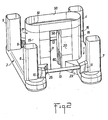
- Figs. 1 and 2 show a drilling vessel having two substantially parallel, horizontal submersible hulls 1 and 2. They have a length of approximately 90m, a width of 17.5m and a height of 8.5m, leaving between them a distance of approximately 30m.
- These hulls 1,2 support a rectangular deck 3 via a mounting or assembly structure having four columns 4,5,6,7 with a substantially square cross-section with a side length of 11 m and rounded angles. These columns are located towards the outside of hulls 1,2 and essentially at the end thereof in the vicinity of the rounded bows thereof, so as to ensure optimum stability of deck 3, whereof the lower surface is approximately 30m above the hulls.
- Buttresses 8,9,10,11 reinforce the foot of the columns on the face thereof turned towards the inside. Buttresses 8,9,10,11 are connected pairwise by braces 12,13 giving the necessary rigidity and strength to the mounting structure.
- Deck 3 which is in fact formed by three superimposed deck stages, is centrally provided with an opening 14 surmounted by a derrick 15.
- the deck also has various installations and equipments which are not shown here, such as various cranes, storage areas, landing area, etc.
- auxiliary means of the deck such as the mooring system and the like, which are well known to the Expert and do not form part of the present invention.
- the mounting structure also has two supplementary columns 16,17, which face one another in the centre of hulls 1,2.
- Columns 16,17 partly engage on hulls 1,2 and are extended towards one another and towards the centre of the deck, their facing faces leaving an intermediate space of about 20m.
- Each column 16,17 has a semi-cylindrical outer part 18,19, which essentially engages on hulls 1,2 and a parallelepipedic inner part 20,21 extending outside hulls 1,2 and descending to the lower level of the latter.
- Horizontal junction or stay plates 22,23,24,25 with the thickness of the hulls 1,2 connect, for reinforcement purposes, the lateral cheeks or flanges of the inner part 20,21 of column 16,17 to the inside of hull 1,2.
- the hulls and columns are constructed by assembling metal plates forming a double hull in accordance with the known naval construction methods.
- Figs. 2 and 4 indicate in a purely informative manner the limits of certain assembly plates.
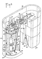
- Fig. 4 shows the double hull, e.g. 19' and 19" of the semi-cylindrical part 19 of column 17.
- Columns 16,17 vertically store pipes of all types, i.e. both drill pipes and risers. Storage takes place on either side of a linear circulation path 30 parallel to the semi-cylindrical wall and to the lateral cheeks of columns 16,17.
- Two parallel rails 31,32 are mounted by adequate support means in the upper part of each column with a clearance enabling them to cover, on either side of the circulation path, the storage space.
- One or more automotive travelling cranes 33 run on rails 31,32 and have a handling device 34 able to move transversely with respect to path 30 along crane 33, so as to be positionable above any point of the storage space.
- Crane 33 can be remotely controlled by means well known to the Expert.
- Handling device 30 is provided in its lower part with a gripping member 34' (e.g. tongs) which can move vertically.
- Risers 35,36 and containers 37 are stored on either side of the circulation path 30 at locations defined by elements 38 (pockets or protuberances) of a floor 39 of the columns and by indentations in two parallel racks 40 (only one being shown) with a lateral escape and which are equipped with a locking system.
- Advantageously elements 38 are constituted by upwardly projecting inverted elastic cones onto which are fitted the lower end of risers 35,36 or containers 37 (whereof the lower end is also in hollow tubular form).
- the locking system is provided through the co-operation of the indentations of rack 40, in the form of open rings, and the upper part of risers 35,36 or containers 37 shaped so as to have an increasing diameter area from bottom to top.
- the diameter of the most narrowest part of said area is sufficiently small to permit the passage of said part into the opening (less than 180 ° ) of the open ring, whilst the diameter of the widest part of said area does not permit said passage.
- risers 35,36 and containers 37 are installed or removed by means of carriages or trolleys 33.
- carriages or trolleys 33 As a result of the linear circulation path and the linear installation on either side thereof of approximately 20 individual storage locations, access to any one of these locations is free and subject to no priority.
- risers 35,36 and containers 37 in each column 16,17, or the extraction thereof takes place either by means of the lifting device of derrick 15, or by means of an independent lifting device, such as that constituted by an inclined elevator ramp 41 starting from the floor 39 of the column and leading to above the level of opening 14 of deck 3.
- Such a ramp has at least one elevator trolley 70 able to run or be guided on ramp 41, being displaced by an endless chain system or preferably a system having pinions 72 and racks 73.
- a system having pinions 72 and racks 73 For example (cf. fig. 5), two parallel racks 73 are mounted on ramp 41 and are subject to the action of pinions 72 of trolley 70 driven by a motor 74 provided on the latter.
- Trolley 70 has a longitudinal frame 75, at the bottom of which is formed a bracket 76, which carries an inverted elastic cone 77 (identical to elements 38), so as to be able to receive the bottom end of a riser 35" (or a container 37).
- Frame 75 has two lateral cheeks 78, between which are mounted wheels 79 guided in the lateral roller tracks 80 of ramp 41.
- the upper part of the frame is terminated by a second bracket carrying an open ring identical to those of rack 40.
- the risers or containers are extracted from the hollow columns in the following way.
- Travelling crane 33 seeks the risers 35,36 or a container 37 in their storage location, brings them vertically along path 30 towards ramp 41 (reference 35',36' in fig. 4) until the foot of the risers is above the inverted cone 77 of trolley 70 of ramp 41.
- a subsequent translation of crane 33 towards ramp 41 stretches out the risers on said ramp (reference 35",36" in fig. 4) and retracts the upper part thereof into the upper open ring of the frame of elevator trolley 70.
- a slight lowering of device 34 makes it possible to correctly fit the bottom of riser 35" onto cone 77 and to lock the top of riser 36" in the open ring provided for this purpose.
- trolley 70 rises on ramp 41.
- the risers can then be taken up by the lifting device of the derrick, or by any independent device.
- the top of the columns 16,17 is covered above rails 31,32 by a surface 51 serving as a storage bridge laterally closed by a shell 50.
- the necessary rigidity and strength is ensured by a bracing system using not shown beams connecting the top of columns 16,17 and 4 to 7.
- the elongated, annular storage bridge 51 surrounds two parallel rails 52,53 connecting the two columns 16,17 and supporting two motorized rolling trolleys 54 used for the movement of blow out preventers 55 for storage purposes.
- the heavy lower part 56 of said preventers is advantageously stored, still supported by trolley 54, in pockets 58 provided in the upper part of each column 16,17 below rails 52,53 in the area not used for storing pipes.
- Each pocket 58 has means for locking the preventer in the stored position.
- the upper part 57 of said preventers (where the bottom part of the risers is located) is advantageously laterally stored on bridge 51.
- the facing faces of columns 16,17 have at their base a conical or prismatic recess 60 for increasing the lateral displacement of the pipes 61 suspended on the lifting device of the derrick.
- the axis of said pipes 61 can form an angle of at least 12 ° with the central vertical axis of the derrick.
- the semisubmersible drilling vessel according to the invention is intended to be sunk into the water with an average height of approximately 24m.
Landscapes
- Engineering & Computer Science (AREA)
- Mechanical Engineering (AREA)
- Life Sciences & Earth Sciences (AREA)
- Geology (AREA)
- Mining & Mineral Resources (AREA)
- Physics & Mathematics (AREA)
- Fluid Mechanics (AREA)
- Chemical & Material Sciences (AREA)
- Ocean & Marine Engineering (AREA)
- Combustion & Propulsion (AREA)
- General Life Sciences & Earth Sciences (AREA)
- Geochemistry & Mineralogy (AREA)
- Environmental & Geological Engineering (AREA)
- Civil Engineering (AREA)
- Structural Engineering (AREA)
- Architecture (AREA)
- Earth Drilling (AREA)
- Mechanical Treatment Of Semiconductor (AREA)
- Reinforced Plastic Materials (AREA)
Description
- The invention relates to a semisubmersible drilling vessel for offshore drilling of the catamaran type, i.e. having two substantially horizontal, parallel and spaced, elongated submersible hulls, a deck supported above said hulls and connected thereto by a mounting structure, the deck having a central opening overhanging the space between the two hulls and being surmounted by a derrick. Said mounting structure has vertical columns, whereof at least two pairs connect the ends of the hulls to the deck.
- Such a general structure is e.g. known from US-A-4 435 108. Moreover, various equipments are provided on such drilling vessels, particularly cranes and means for the storage and handling of pipes according to the features of the first part of the
claim 1. - The term pipes is understood to mean two basic types of long cylindrical elements used in large quantities on such a drilling vessel and namely drill pipes having a length of e.g. about 10 metres and a diameter of about 12 centimeters and risers having a length of about 15 metres and a diameter of a little more than one metre.
- Usually these pipes are stored horizontally. It is therefore necessary to provide a handling means, like that known from GB-A-1319270, which is designed for lifting the pipes and for placing them in their vertical use position.
- To obviate this needless change of position of the pipes, means have already been proposed for the vertical storage of individual drill pipes. Thus, in US-A-4044895 or GB-A-1494964, the drill pipes are stored in juxtaposed manner over the entire surface of a storage area located beneath the deck of the drilling vessel, so as to lower the centre of gravity thereof. Storage particularly suffers from the disadvantage of occupying a considerable floor or ground space and of only permitting a successive access to the different drill rods, unless a device is provided for the upward extraction thereof and which is able to move above the entire ground surface, which increases the overall dimensions.
- An article in the journal "Ocean Industry", August 1985 reports on a catamaran-type drilling vessel project, in which the risers are stored vertically within a parallelepipedic median caisson connecting the two hulls of the catamaran. However, this median caisson suffers from serious disadvantages. On the one hand its presence between the hulls is prejudicial to the handling of the templates, cf. US-A-4435108 and whose overall dimensions are about 10 x 40 m. Moreover, this median caisson produces a considerable draught of water and is highly exposed to a swell. There is nothing which outweighs the advantages of a catamaran more than adding a cross-wall thereto, which makes it possible to significantly increase the number of anchoring means.
- According to another drilling vessel project of Friede & Goldman (New Orleans, Louisiana, USA) and called the "Trendsetter", below the derrick is provided an annular, central, cylindrical caisson, in whose peripheral thickness are vertically stored the risers (see "World Oil", Vol 203, No. 4, Oct. 1986, pages 41-43, Houston Texas, US; R.W. Mow- ell et al.:"New semi features better leave response, vertical riser storage"). However, as in the case of the previous project, the presence of a central caisson is prejudicial to the handling of the templates. In addition, the volume of this central caisson must be severely limited otherwise it would offer an excessive surface area to the waves. Furthermore, the drill pipes are still horizontally stored. This caisson is also exposed to very high forces and stresses as a result of hydrostatic force, which involves a considerable bracing. However, braces are generally the weak point of drilling vessels due to the relative weakness of the welds. It is therefore best not to have an excessive increase in the number of braces. Finally, there is a risk of the water rising within the open volume of the caisson during ramming movements of the drilling vessel, which would have the effect of producing a prejudicial swabbing effect.
- The problem of the present invention is to propose a novel catamaran-type semisubmersible drilling vessel not suffering from the aforementioned disadvantages and permitting the vertical storage of both the risers and the drill pipes without prejudicing the stability of the drilling vessel and without weakening its structure.
- According to the invention this problem is solved in that the mounting or assembly structure connecting the hulls to the deck has at least two hollow columns forming caissons and internally provided with the pipe storage means arranged so as to permit vertical storage, said columns facing and being spaced from one another, being essentially located in the centre of each hull.
- Advantageously storage is organised over the entire height of the columns so as to bring about a maximum increase in the storage capacity and reduce the centre of gravity of the drilling vessel. In addition, several pipe lengths are vertically stored.
- Due to the fact that the columns of the mounting structure are used for storage purposes, there is no longer any need to provide a significant supplementary bracing. As the columns are spaced from one another, the central space gives the possibility of handling the templates and there is no cross-wall with respect to the catamaran direction.
- The shape of the columns is chosen in such a way as to offer a large storage volume, but in particular a volume adapted to a linear organisation of the storage parallel to the vertical walls of the columns. To this end, the latter advantageously have a semi-cylindrical part turned towards the outside of the vessel and which is internally extended by two lateral flanges or cheeks, which makes it possible to easily provide a direct access system at each individual storage location by a lateral escape on either side of a linear circulation path along which the storage is organised. This direct access system advantageously has a travelling crane equipped with handling tongs. The extraction of the pipes from the storage column advantageously takes place by means of an elevator ramp.
- Due to the fact that the pipes are essentially stored on two rows parallel to the semi-cylindrical walls and to the lateral cheeks of the hollow columns, in the centre of the latter there remains a volume available for the storage of other materials. Thus, there are several pulverulent material silo levels located as low as possible in the column for bringing about a maximum centre of gravity reduction. In this way it is possible to distribute a load of 1500 tonnes on the columns.
- Above the location of these silos, each storage column has a pocket or cavity accessible by means of rails connecting the upper part of the columns and handling carriages or trolleys. These pockets serve to store blow out preventers.
- These installations perfectly lend themselves to a complete automation of the handling of the different stored products or components.
- Other advantages and features of the invention can be gathered from a preferred embodiment with- reference to the attached drawings, wherein show:
- Fig. 1 a diagrammatic longitudinal perspective view of an embodiment of the drilling vessel according to the invention.
- Fig. 2 a diagrammatic transverse perspective view of the vessel according to fig. 1, the deck having been removed.
- Fig. 3 a diagrammatic plan view of the vessel of fig. 2.
- Fig. 4 a partly broken away perspective view of two supplementary columns within which the pipes are stored.
- Fig. 5 a side view showing the detail of the lower part of the elevator ramp.
- Figs. 1 and 2 show a drilling vessel having two substantially parallel, horizontal
submersible hulls hulls rectangular deck 3 via a mounting or assembly structure having fourcolumns hulls deck 3, whereof the lower surface is approximately 30m above the hulls. -
Buttresses Buttresses braces -
Deck 3, which is in fact formed by three superimposed deck stages, is centrally provided with an opening 14 surmounted by aderrick 15. The deck also has various installations and equipments which are not shown here, such as various cranes, storage areas, landing area, etc. There is also no need to describe the auxiliary means of the deck, such as the mooring system and the like, which are well known to the Expert and do not form part of the present invention. - According to the invention, the mounting structure also has two
supplementary columns hulls Columns hulls - Each
column outer part hulls inner part hulls stay plates hulls inner part column hull - The hulls and columns are constructed by assembling metal plates forming a double hull in accordance with the known naval construction methods. Figs. 2 and 4 indicate in a purely informative manner the limits of certain assembly plates. Fig. 4 shows the double hull, e.g. 19' and 19" of the
semi-cylindrical part 19 ofcolumn 17.Columns linear circulation path 30 parallel to the semi-cylindrical wall and to the lateral cheeks ofcolumns - Two
parallel rails 31,32 are mounted by adequate support means in the upper part of each column with a clearance enabling them to cover, on either side of the circulation path, the storage space. One or more automotive travellingcranes 33 run onrails 31,32 and have ahandling device 34 able to move transversely with respect topath 30 alongcrane 33, so as to be positionable above any point of the storage space.Crane 33 can be remotely controlled by means well known to the Expert.Handling device 30 is provided in its lower part with a gripping member 34' (e.g. tongs) which can move vertically. - Bearing in mind the dimensions of risers (50 feet, i.e. 15.24m) and drill pipes (30 feet, i.e. 9.14m) and the available height in the columns (approximately 40m), it has appeared advantageous to group the risers by the pairwise joining thereof, cf. 35,36 and to group the drill pipes in strings of three pipes placed end to end. As the diameter of the latter (5 inches, i.e. 12.7cm) is well below that of the risers (46 inches, i.e. 116.84cm), the strings of pipes are grouped in drums of twelve within a
cylindrical container 37, whose diameter is close to that of the risers. Drum systems are known from the aforementioned article in Ocean Industry. -
Risers containers 37 are stored on either side of thecirculation path 30 at locations defined by elements 38 (pockets or protuberances) of afloor 39 of the columns and by indentations in two parallel racks 40 (only one being shown) with a lateral escape and which are equipped with a locking system. - Advantageously elements 38 are constituted by upwardly projecting inverted elastic cones onto which are fitted the lower end of
risers rack 40, in the form of open rings, and the upper part ofrisers containers 37 shaped so as to have an increasing diameter area from bottom to top. The diameter of the most narrowest part of said area is sufficiently small to permit the passage of said part into the opening (less than 180°) of the open ring, whilst the diameter of the widest part of said area does not permit said passage. Thus, after retractingrisers container 37 into one of the open rings ofrack 40 by the narrow part thereof, it is sufficient to lower device 34' in order to lock said risers or said container. - Within each column,
risers containers 37 are installed or removed by means of carriages ortrolleys 33. As a result of the linear circulation path and the linear installation on either side thereof of approximately 20 individual storage locations, access to any one of these locations is free and subject to no priority. - The placing of
risers containers 37 in eachcolumn derrick 15, or by means of an independent lifting device, such as that constituted by aninclined elevator ramp 41 starting from thefloor 39 of the column and leading to above the level ofopening 14 ofdeck 3. - The general principle of such elevator ramps is well known to the Expert and reference can e.g. be made to US-A-4379676. Such a ramp has at least one
elevator trolley 70 able to run or be guided onramp 41, being displaced by an endless chain system or preferably asystem having pinions 72 and racks 73. For example (cf. fig. 5), twoparallel racks 73 are mounted onramp 41 and are subject to the action ofpinions 72 oftrolley 70 driven by amotor 74 provided on the latter. -
Trolley 70 has a longitudinal frame 75, at the bottom of which is formed abracket 76, which carries an inverted elastic cone 77 (identical to elements 38), so as to be able to receive the bottom end of ariser 35" (or a container 37). Frame 75 has twolateral cheeks 78, between which are mountedwheels 79 guided in the lateral roller tracks 80 oframp 41. The upper part of the frame is terminated by a second bracket carrying an open ring identical to those ofrack 40. - The risers or containers are extracted from the hollow columns in the following way. Travelling
crane 33 seeks therisers container 37 in their storage location, brings them vertically alongpath 30 towards ramp 41 (reference 35',36' in fig. 4) until the foot of the risers is above theinverted cone 77 oftrolley 70 oframp 41. A subsequent translation ofcrane 33 towardsramp 41 stretches out the risers on said ramp (reference 35",36" in fig. 4) and retracts the upper part thereof into the upper open ring of the frame ofelevator trolley 70. A slight lowering ofdevice 34 makes it possible to correctly fit the bottom ofriser 35" ontocone 77 and to lock the top ofriser 36" in the open ring provided for this purpose. After the disengagement of travellingcrane 33,trolley 70 rises onramp 41. On leavingdeck 3, the risers can then be taken up by the lifting device of the derrick, or by any independent device. - Due to the fact that the two
columns risers containers 37, the extraction thereof can be very fast and can overlap. A reverse process makes it possible to install the risers and containers. - The top of the
columns rails 31,32 by asurface 51 serving as a storage bridge laterally closed by ashell 50. The necessary rigidity and strength is ensured by a bracing system using not shown beams connecting the top ofcolumns - The elongated,
annular storage bridge 51 surrounds twoparallel rails columns motorized rolling trolleys 54 used for the movement of blow outpreventers 55 for storage purposes. - The heavy
lower part 56 of said preventers is advantageously stored, still supported bytrolley 54, inpockets 58 provided in the upper part of eachcolumn rails pocket 58 has means for locking the preventer in the stored position. Theupper part 57 of said preventers (where the bottom part of the risers is located) is advantageously laterally stored onbridge 51. - In order to use a stored blow out
preventer 55, it is merely necessary to bring it with the aid of itstrolley 54 into the axis of the derrick, to take it up by using the lifting device of said derrick, to allow the escape of thetrolley 54 shaped for this purpose and then to install it in the conventional way. The storage of a preventer takes place in the reverse order. - Within each column, beneath the preventer storage pockets 58, the available space is devoted to storage on two levels of powder material silos 59 (barite, cement, etc.).
- The facing faces of
columns prismatic recess 60 for increasing the lateral displacement of the pipes 61 suspended on the lifting device of the derrick. In its maximum lateral displacement position, the axis of said pipes 61 can form an angle of at least 12° with the central vertical axis of the derrick. - The semisubmersible drilling vessel according to the invention is intended to be sunk into the water with an average height of approximately 24m.
Claims (9)
Applications Claiming Priority (2)
| Application Number | Priority Date | Filing Date | Title |
|---|---|---|---|
| FR8616942A FR2607773B1 (en) | 1986-12-03 | 1986-12-03 | SEMI-SUBMERSIBLE CATAMARAN-TYPE PLATFORM FOR DRILLING AT SEA |
| FR8616942 | 1986-12-03 |
Publications (2)
| Publication Number | Publication Date |
|---|---|
| EP0273474A1 EP0273474A1 (en) | 1988-07-06 |
| EP0273474B1 true EP0273474B1 (en) | 1990-08-01 |
Family
ID=9341531
Family Applications (1)
| Application Number | Title | Priority Date | Filing Date |
|---|---|---|---|
| EP87202243A Expired - Lifetime EP0273474B1 (en) | 1986-12-03 | 1987-11-17 | Catamaran-type semisubmersible drilling vessel for offshore drilling |
Country Status (8)
| Country | Link |
|---|---|
| US (1) | US4899682A (en) |
| EP (1) | EP0273474B1 (en) |
| JP (1) | JPH086305B2 (en) |
| KR (1) | KR970010826B1 (en) |
| CA (1) | CA1300986C (en) |
| DE (1) | DE3764075D1 (en) |
| FR (1) | FR2607773B1 (en) |
| NO (1) | NO171774C (en) |
Families Citing this family (26)
| Publication number | Priority date | Publication date | Assignee | Title |
|---|---|---|---|---|
| NL9401208A (en) * | 1994-07-22 | 1996-03-01 | Heerema Group Services Bv | Method and device for drilling for oil or gas. |
| NL1006287C2 (en) * | 1997-06-11 | 1998-12-14 | Workships Contractors Bv | Semi-submersible mobile drilling vessel. |
| US6378450B1 (en) * | 1998-05-01 | 2002-04-30 | Friede & Goldman, Ltd. | Dynamically positioned semi-submersible drilling vessel with slender horizontal braces |
| AU2003206256B2 (en) * | 2002-02-01 | 2007-11-15 | Sbm Schiedam B.V. | Multi hull barge |
| US6766860B2 (en) * | 2002-02-22 | 2004-07-27 | Globalsantafe Corporation | Multi-activity offshore drilling facility having a support for tubular string |
| BRPI0511766A (en) * | 2004-06-02 | 2008-01-08 | Stena Drilling Ltd | probe for various activities |
| NO322520B1 (en) * | 2004-12-23 | 2006-10-16 | Fred Olsen Energy Asa | Device for storing rudder, device for transporting rudder and method for taking apart a rudder string |
| US8925647B2 (en) * | 2006-06-30 | 2015-01-06 | Stena Drilling Ltd. | Triple activity drilling ship |
| SE531718C2 (en) * | 2006-10-19 | 2009-07-21 | Gva Consultants Ab | Integrated drill deck and blowout fuse management |
| SE530900C2 (en) * | 2007-04-02 | 2008-10-14 | Gva Consultants Ab | drilling device |
| KR101594854B1 (en) * | 2008-02-15 | 2016-02-18 | 아이티알이씨 비. 브이. | Offshore drilling vessel |
| BRPI0803619B1 (en) * | 2008-09-19 | 2018-06-12 | Petroleo Brasileiro S.A. - Petrobras | SIMULTANEOUS IMPLEMENTATION SYSTEM FOR MARINE PROBE OPERATION AND METHOD |
| WO2010048665A1 (en) * | 2008-10-28 | 2010-05-06 | Piet Ellnor | Ocean going transport vessel with docking arrangements |
| WO2011036237A1 (en) * | 2009-09-24 | 2011-03-31 | Single Buoy Moorings Inc. | Vertical offshore flexible pipeline assembly |
| US8733472B2 (en) * | 2010-09-13 | 2014-05-27 | Christopher Magnuson | Multi-operational multi-drilling system |
| NL2005912C2 (en) * | 2010-12-23 | 2012-06-27 | Itrec Bv | Drilling installation and offshore drilling vessel with drilling installation. |
| SG11201401714UA (en) * | 2011-10-05 | 2014-09-26 | Seahorse Equip Corp | Method and apparatus for drilling multiple subsea wells from an offshore platform at a single site |
| KR101276130B1 (en) * | 2011-12-02 | 2013-06-18 | 대우조선해양 주식회사 | Locking device of riser bridge and bop crane for drillship |
| KR200469615Y1 (en) * | 2012-03-26 | 2013-10-25 | 대우조선해양 주식회사 | Catamaran type drilling ship |
| WO2014187816A1 (en) | 2013-05-20 | 2014-11-27 | A.P. Møller - Mærsk A/S | Riser handling on a drilling rig and a flip and service machine for riser handling on a drilling rig |
| JP5820861B2 (en) * | 2013-10-08 | 2015-11-24 | 財團法人船舶▲き▼海洋▲産▼業研發中心 | Construction method of offshore building |
| US9446825B1 (en) | 2013-12-10 | 2016-09-20 | Hugh Francis Gallagher | Self-propelled, catamaran-type, dual-application, semisubmersible ship with hydrodynamic hulls and columns |
| KR20150144486A (en) | 2014-06-17 | 2015-12-28 | 대우조선해양 주식회사 | Mono-hull deep-draft drilling ship and drilling facility including the same |
| CN109070971A (en) * | 2016-03-03 | 2018-12-21 | 吉宝岸外与海事技术中心 | Super elliptical columns on a semi-submersible vessel |
| US20190144083A1 (en) * | 2016-04-27 | 2019-05-16 | Cefront Technology As | Offshore vessel for production and storage of petroleum products |
| US12172737B2 (en) | 2022-06-11 | 2024-12-24 | Hugh Francis Gallagher | Semi-autonomous immersible waterborne dock enclosure |
Family Cites Families (19)
| Publication number | Priority date | Publication date | Assignee | Title |
|---|---|---|---|---|
| US2690847A (en) * | 1953-07-15 | 1954-10-05 | Standard Oil Dev Co | Device for positioning pipe in a drilling derrick |
| US3513996A (en) * | 1968-07-31 | 1970-05-26 | Lee C Moore | Drill pipe handling apparatus |
| US3559821A (en) * | 1969-06-19 | 1971-02-02 | Ralph Edward James | Drill pipe handling apparatus |
| FR2065728B1 (en) * | 1969-10-10 | 1974-10-31 | Chevron Res | |
| US3774780A (en) * | 1972-09-07 | 1973-11-27 | W Buffington | Portable pipe pick-up, conveying and racking device |
| DE2336903A1 (en) * | 1973-07-20 | 1975-02-06 | Gerhard Rippen | Concrete pipe handling grab - has hooks sliding in pipes actuated via linkage by single vertical ram |
| US3929235A (en) * | 1974-11-22 | 1975-12-30 | Byron Jackson Inc | System for handling and racking pipe in the hold of a vessel |
| US3987910A (en) * | 1975-02-07 | 1976-10-26 | Siro Brunato | Apparatus for racking drill pipes on floater type platforms |
| US3986619A (en) * | 1975-06-11 | 1976-10-19 | Lee C. Moore Corporation | Pipe handling apparatus for oil well drilling derrick |
| NO144976C (en) * | 1976-04-01 | 1981-12-16 | Golar Nor Offshore As | OUR DEVICE FOR HANDLING AND STORAGE OF RIGS AND DRILLS |
| US4044895A (en) * | 1976-06-04 | 1977-08-30 | Barney Silis Adams, Jr. | Pipe racking system |
| DE2735172C3 (en) * | 1977-08-02 | 1980-07-03 | Mannesmann Ag, 4000 Duesseldorf | Trough-like pipe collecting device |
| US4379676A (en) * | 1980-02-27 | 1983-04-12 | Ingram Corporation | Pipe handling system |
| US4435108A (en) * | 1981-08-11 | 1984-03-06 | Sedco, Inc. | Method of installing sub-sea templates |
| CA1151144A (en) * | 1982-02-18 | 1983-08-02 | Kenneth Layton | Pipe handling method and apparatus |
| NL8303115A (en) * | 1983-09-08 | 1985-04-01 | Marine Structure Consul | Undersea pile with air-lifting system - has bottomless conical or pyramidal chamber with fluidisation devices on outsides of walls |
| NL8303671A (en) * | 1983-10-25 | 1985-05-17 | Marine Structure Consul | Column supported platform-lifting mechanism - has top yoke on platform with slotted tubular component forming pawl guide |
| US4646672A (en) * | 1983-12-30 | 1987-03-03 | William Bennett | Semi-subersible vessel |
| NL8402734A (en) * | 1984-09-07 | 1986-04-01 | Schelde Nv | DEVICE FOR STORING PIPES. |
-
1986
- 1986-12-03 FR FR8616942A patent/FR2607773B1/en not_active Expired
-
1987
- 1987-11-17 EP EP87202243A patent/EP0273474B1/en not_active Expired - Lifetime
- 1987-11-17 DE DE8787202243T patent/DE3764075D1/en not_active Expired - Lifetime
- 1987-11-19 US US07/123,020 patent/US4899682A/en not_active Expired - Lifetime
- 1987-11-20 KR KR1019870013107A patent/KR970010826B1/en not_active Expired - Fee Related
- 1987-12-02 NO NO875026A patent/NO171774C/en not_active IP Right Cessation
- 1987-12-02 CA CA000553326A patent/CA1300986C/en not_active Expired - Fee Related
- 1987-12-03 JP JP62306839A patent/JPH086305B2/en not_active Expired - Lifetime
Also Published As
| Publication number | Publication date |
|---|---|
| CA1300986C (en) | 1992-05-19 |
| FR2607773A1 (en) | 1988-06-10 |
| NO875026L (en) | 1988-06-06 |
| DE3764075D1 (en) | 1990-09-06 |
| NO171774C (en) | 1993-05-05 |
| NO171774B (en) | 1993-01-25 |
| KR970010826B1 (en) | 1997-07-01 |
| JPS63219720A (en) | 1988-09-13 |
| FR2607773B1 (en) | 1989-03-31 |
| EP0273474A1 (en) | 1988-07-06 |
| JPH086305B2 (en) | 1996-01-24 |
| KR880007320A (en) | 1988-08-26 |
| NO875026D0 (en) | 1987-12-02 |
| US4899682A (en) | 1990-02-13 |
Similar Documents
| Publication | Publication Date | Title |
|---|---|---|
| CA1300986C (en) | Catamaran-type semisubmersible drilling vessel for offshore drilling | |
| CN107416141B (en) | offshore drilling vessel | |
| US4108318A (en) | Apparatus for offshore handling and running of a BOP stack | |
| US6375391B1 (en) | Guide device for production risers for petroleum production with a “dry tree semisubmersible” at large sea depths | |
| EP2823105B1 (en) | An offshore system comprising a rig and a cantilever | |
| US4666340A (en) | Offshore platform with removable modules | |
| US4607982A (en) | Method and apparatus for installation of an offshore platform | |
| CN101405473B (en) | Apparatus for storing tubular elements and apparatus for handling tubular elements | |
| CN1350499A (en) | working boat | |
| US6139224A (en) | Semi-submersible platform for offshore oil field operation and method of installing a platform of this kind | |
| AU775276B2 (en) | Method for installing a number of risers or tendons and vessel for carrying out said method | |
| US20250010961A1 (en) | Installation for the load-out into the water of a heavy load | |
| US4111144A (en) | Ship's docking plant | |
| EP0039590A2 (en) | Offshore platform and method of constructing, erecting and dismantling same | |
| KR20100087094A (en) | Method for installing a drilling apparatus on a rig and for preparing drilling operations | |
| AU2005319792B2 (en) | Device for storage of tubulars, apparatus for handling tubulars and a method for disassembling a pipe string | |
| JPS5857571B2 (en) | Joints that secure the structure to the seabed | |
| CA1078631A (en) | Oil-production platform and method of assembling and installing the same on a sea bed | |
| EP3911835B1 (en) | Modular riser section storage and handling system | |
| US4448570A (en) | Method of constructing a concrete off-shore structure more than 200 m high stabilized on the sea bed by its own weight | |
| US3394553A (en) | Underwater anchored pillar for supporting a platform | |
| GB2175945A (en) | Offshore production systems | |
| EP4382723A2 (en) | Semi-submersible drilling vessel, e.g. for use in a harsh environment | |
| KR810001197B1 (en) | Ship's docking plant | |
| EP0192311A2 (en) | A method of placing a platform on a support structure surrounded by water, in particular in high seas, and a vessel for carrying out said method |
Legal Events
| Date | Code | Title | Description |
|---|---|---|---|
| PUAI | Public reference made under article 153(3) epc to a published international application that has entered the european phase |
Free format text: ORIGINAL CODE: 0009012 |
|
| AK | Designated contracting states |
Kind code of ref document: A1 Designated state(s): DE GB IT NL |
|
| 17P | Request for examination filed |
Effective date: 19880809 |
|
| 17Q | First examination report despatched |
Effective date: 19891002 |
|
| RIN1 | Information on inventor provided before grant (corrected) |
Inventor name: JITENDRA PRASAD Inventor name: THANH DANG TRAN Inventor name: HAMPTON, JAMES Inventor name: CHEVALLIER, JEAN Inventor name: POUGET, GILLES |
|
| GRAA | (expected) grant |
Free format text: ORIGINAL CODE: 0009210 |
|
| ITF | It: translation for a ep patent filed | ||
| AK | Designated contracting states |
Kind code of ref document: B1 Designated state(s): DE GB IT NL |
|
| REF | Corresponds to: |
Ref document number: 3764075 Country of ref document: DE Date of ref document: 19900906 |
|
| PLBE | No opposition filed within time limit |
Free format text: ORIGINAL CODE: 0009261 |
|
| STAA | Information on the status of an ep patent application or granted ep patent |
Free format text: STATUS: NO OPPOSITION FILED WITHIN TIME LIMIT |
|
| 26N | No opposition filed | ||
| ITTA | It: last paid annual fee | ||
| PGFP | Annual fee paid to national office [announced via postgrant information from national office to epo] |
Ref country code: NL Payment date: 20001030 Year of fee payment: 14 |
|
| PGFP | Annual fee paid to national office [announced via postgrant information from national office to epo] |
Ref country code: GB Payment date: 20001113 Year of fee payment: 14 |
|
| PG25 | Lapsed in a contracting state [announced via postgrant information from national office to epo] |
Ref country code: GB Free format text: LAPSE BECAUSE OF NON-PAYMENT OF DUE FEES Effective date: 20011117 |
|
| REG | Reference to a national code |
Ref country code: GB Ref legal event code: IF02 |
|
| PG25 | Lapsed in a contracting state [announced via postgrant information from national office to epo] |
Ref country code: NL Free format text: LAPSE BECAUSE OF NON-PAYMENT OF DUE FEES Effective date: 20020601 |
|
| PGFP | Annual fee paid to national office [announced via postgrant information from national office to epo] |
Ref country code: DE Payment date: 20020627 Year of fee payment: 15 |
|
| GBPC | Gb: european patent ceased through non-payment of renewal fee |
Effective date: 20011117 |
|
| NLV4 | Nl: lapsed or anulled due to non-payment of the annual fee |
Effective date: 20020601 |
|
| PG25 | Lapsed in a contracting state [announced via postgrant information from national office to epo] |
Ref country code: DE Free format text: LAPSE BECAUSE OF NON-PAYMENT OF DUE FEES Effective date: 20030603 |
|
| PG25 | Lapsed in a contracting state [announced via postgrant information from national office to epo] |
Ref country code: IT Free format text: LAPSE BECAUSE OF NON-PAYMENT OF DUE FEES;WARNING: LAPSES OF ITALIAN PATENTS WITH EFFECTIVE DATE BEFORE 2007 MAY HAVE OCCURRED AT ANY TIME BEFORE 2007. THE CORRECT EFFECTIVE DATE MAY BE DIFFERENT FROM THE ONE RECORDED. Effective date: 20051117 |