EP0273383A2 - Molded plastic material container - Google Patents
Molded plastic material container Download PDFInfo
- Publication number
- EP0273383A2 EP0273383A2 EP87119117A EP87119117A EP0273383A2 EP 0273383 A2 EP0273383 A2 EP 0273383A2 EP 87119117 A EP87119117 A EP 87119117A EP 87119117 A EP87119117 A EP 87119117A EP 0273383 A2 EP0273383 A2 EP 0273383A2
- Authority
- EP
- European Patent Office
- Prior art keywords
- container
- flange
- support flange
- closure
- container according
- Prior art date
- Legal status (The legal status is an assumption and is not a legal conclusion. Google has not performed a legal analysis and makes no representation as to the accuracy of the status listed.)
- Withdrawn
Links
Images
Classifications
-
- B—PERFORMING OPERATIONS; TRANSPORTING
- B65—CONVEYING; PACKING; STORING; HANDLING THIN OR FILAMENTARY MATERIAL
- B65D—CONTAINERS FOR STORAGE OR TRANSPORT OF ARTICLES OR MATERIALS, e.g. BAGS, BARRELS, BOTTLES, BOXES, CANS, CARTONS, CRATES, DRUMS, JARS, TANKS, HOPPERS, FORWARDING CONTAINERS; ACCESSORIES, CLOSURES, OR FITTINGS THEREFOR; PACKAGING ELEMENTS; PACKAGES
- B65D77/00—Packages formed by enclosing articles or materials in preformed containers, e.g. boxes, cartons, sacks or bags
- B65D77/10—Container closures formed after filling
- B65D77/20—Container closures formed after filling by applying separate lids or covers, i.e. flexible membrane or foil-like covers
- B65D77/2024—Container closures formed after filling by applying separate lids or covers, i.e. flexible membrane or foil-like covers the cover being welded or adhered to the container
-
- B—PERFORMING OPERATIONS; TRANSPORTING
- B65—CONVEYING; PACKING; STORING; HANDLING THIN OR FILAMENTARY MATERIAL
- B65D—CONTAINERS FOR STORAGE OR TRANSPORT OF ARTICLES OR MATERIALS, e.g. BAGS, BARRELS, BOTTLES, BOXES, CANS, CARTONS, CRATES, DRUMS, JARS, TANKS, HOPPERS, FORWARDING CONTAINERS; ACCESSORIES, CLOSURES, OR FITTINGS THEREFOR; PACKAGING ELEMENTS; PACKAGES
- B65D1/00—Containers having bodies formed in one piece, e.g. by casting metallic material, by moulding plastics, by blowing vitreous material, by throwing ceramic material, by moulding pulped fibrous material, by deep-drawing operations performed on sheet material
- B65D1/40—Details of walls
- B65D1/42—Reinforcing or strengthening parts or members
- B65D1/46—Local reinforcements, e.g. adjacent closures
-
- B—PERFORMING OPERATIONS; TRANSPORTING
- B65—CONVEYING; PACKING; STORING; HANDLING THIN OR FILAMENTARY MATERIAL
- B65D—CONTAINERS FOR STORAGE OR TRANSPORT OF ARTICLES OR MATERIALS, e.g. BAGS, BARRELS, BOTTLES, BOXES, CANS, CARTONS, CRATES, DRUMS, JARS, TANKS, HOPPERS, FORWARDING CONTAINERS; ACCESSORIES, CLOSURES, OR FITTINGS THEREFOR; PACKAGING ELEMENTS; PACKAGES
- B65D2577/00—Packages formed by enclosing articles or materials in preformed containers, e.g. boxes, cartons, sacks, bags
- B65D2577/10—Container closures formed after filling
- B65D2577/20—Container closures formed after filling by applying separate lids or covers
- B65D2577/2041—Pull tabs
- B65D2577/205—Pull tabs integral with the closure
Definitions
- This invention relates in general to new and useful improvements in containers, and more particularly to a molded plastic material container which is to receive a closure in sealed relation.
- a molded plastic material container in the form of a box or the like, which container is of a multi-sided construction and each side thereof terminates in an upper flange assembly which includes an inner support flange for receiving in sealed relation a closure.
- the container may contain a flowable product which may include liquids.
- the container is subject to being dropped at which time the product will rush to the lowermost part of the container and have a tendency to attempt to separate the closure from the container. This tendency of the closure to separate from the container is increased if the support flange is permitted to deform.
- the flange assembly also includes an outer upstanding bead with the bead forming both means for centering the closure on the support flange and shock absorbing means.
- the bead extends upwardly from the support flange to an inverted bight portion and then terminates in an outer leg.
- the outer leg may terminate in a peripheral flange. When dropped, the outer leg resiliently moves towards the support flange by a bending of the bight portion, thereby leaving the support flange substantially shock free.
- each side of the container may also be reinforced by an inwardly directed stiffening flange disposed below the support flange.
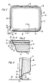
- FIG. 1 a package generally identified by the numeral 10 and including a container, which is the subject of the invention and identified by the numeral 12, and a closure generally identified by the numeral 14.
- the container 12 is formed with a plurality of sides and the illustrated container is rectangular in outline.
- the container 12 includes a bottom wall 16 and a plurality of side walls 18.
- each side wall 18 terminates at its upper end in a flange assembly generally identified by the numeral 20.
- Each flange assembly 20 includes a support flange 22 on which the peripheral edge of the closure 14 is seated and to which the closure 14 is heat bonded in a manner which is not the subject of this invention.
- the flange assembly 20 includes an upstanding bead generally identified by the numeral 24.
- the bead 24 includes an inner upstanding leg 26 which is integrally connected to the outer edge of the support flange 22.
- the inner leg 26 terminates in an inverted bight portion 28 which in turn terminates in a depending outer leg 30.
- the outer leg 30 carries a terminal peripheral flange 32 which is outwardly directed. Further, it will be seen that the outer leg 30 is longer than the inner leg 26 so that the outer leg 30 extends down below the support flange 22.
- each side 18 may be of a stepped configuration so as to include an inwardly directed stiffening flange 34 which is connected to the inner edge of the support flange 22 by an upstanding portion 36.
- corner flange assemblies 38 which are rounded and which join together the flange assemblies 20 of the sides.
- the closure 14 includes a radially projecting pull tab 40 which is utilized to rupture the bond between the closure 14 and the support flange 22 in the opening of the package 10. Therefore, there is a modified corner flange assembly 42 at the fourth corner of the container 12.
- the corner flange assembly 42 differs from the corner flange assemblies 38 in that it is free of the bead 24 with the bead 24 terminating at 44 adjacent the corner flange assembly 42.
- the bead 24 serves to align the closure 14 with the container 12 in the manner best shown in Figure 2. While there is a slight clearance between the periphery of the closure 14 and the inner leg 26 of the bead 24, the clearance is one which is to facilitate automatic alignment.
- the bead 24 also functions as shock absorbing means as is best shown in Figure 3.
- the package 10 includes a product 46 which may be a flowable product so that when the package 10 is dropped, the product 46 will flow towards the lowermost one of the sides 18 and attempt to rupture the bond between the closure 14 and the support flange 22. If the support flange 22 is subjected to an undue shock, this in combination with the pressure exerted by the product 46 would result in the rupture of the bond between the closure 14 and the support flange 22. However, it will be seen that when the peripheral flange 22 strikes a surface, such as a floor 48, the bight portion 28 will deform permitting the outer leg 30 to deflect upwardly towards the inner leg 26, as is shown by dotted lines. Since the shock is absorbed in the bight portion 28, little or no shock is transmitted to the support flange 22.
- a product 46 which may be a flowable product so that when the package 10 is dropped, the product 46 will flow towards the lowermost one of the sides 18 and attempt to rupture the bond between the closure 14 and the support flange 22. If the support flange
- both the container 12 and the closure 14 have both been illustrated as being of a single thickness, in practice, both the container 12 and the closure 14 will be formed of a laminated web including a barrier layer. Further, the barrier layer of the closure 14 may be in the form of an aluminum foil layer which may be inductively heated so as to heat seal the closure 14 to the container 12.
Landscapes
- Engineering & Computer Science (AREA)
- Mechanical Engineering (AREA)
- Ceramic Engineering (AREA)
- Rigid Containers With Two Or More Constituent Elements (AREA)
- Packages (AREA)
- Shaping Of Tube Ends By Bending Or Straightening (AREA)
Abstract
A flange assembly (20) of a molded plastic container (12) which is multi-sided. Each side terminates at its upper edge in the flange assembly (20) and the flange assembly (20) includes an inner support flange (22) to which a closure (14) may be bonded. Outwardly of the support flange (22) is an upstanding shock absorbing bead (24) which additionally functions to center the closure (14) on the container (12). The bead (24) includes an inner leg (26) which is integrally connected to the support flange (22) and an outer leg (30) with the inner leg (26) being joined to the outer leg (30) by a deformable bight portion (28). When dropped on the side, the package (10) formed of the closed container (12) will have the shock of the impact of striking a surface, such as a floor, absorbed by the deformation of the bead (24).
Description
- This invention relates in general to new and useful improvements in containers, and more particularly to a molded plastic material container which is to receive a closure in sealed relation.
- In accordance with this invention, there has been developed a molded plastic material container in the form of a box or the like, which container is of a multi-sided construction and each side thereof terminates in an upper flange assembly which includes an inner support flange for receiving in sealed relation a closure. The container may contain a flowable product which may include liquids.
- Like other containers, the container is subject to being dropped at which time the product will rush to the lowermost part of the container and have a tendency to attempt to separate the closure from the container. This tendency of the closure to separate from the container is increased if the support flange is permitted to deform.
- In accordance with this invention the flange assembly also includes an outer upstanding bead with the bead forming both means for centering the closure on the support flange and shock absorbing means.
- Most particularly, the bead extends upwardly from the support flange to an inverted bight portion and then terminates in an outer leg. The outer leg, in turn, may terminate in a peripheral flange. When dropped, the outer leg resiliently moves towards the support flange by a bending of the bight portion, thereby leaving the support flange substantially shock free.
- If desired, each side of the container may also be reinforced by an inwardly directed stiffening flange disposed below the support flange.
- With the above and other objects in view that will hereinafter appear, the nature of the invention will be more clearly understood by reference to the following detailed description, the appended claims, and the several views illustrated in the accompanying drawing.
- Figure 1 is a plan view of a container formed in accordance with this invention and closed by means of a closure.
- Figure 2 is an enlarged fragmentary vertical section view taken generally along the line 2-2 of Figure 1 and shows generally the cross section of the container and the relationship of the closure thereto.
- Figure 3 is a vertical sectional view similar to Figure 2 but with the container rotated and the flange assembly thereof at one side striking a surface, for example, a floor.
- Referring now to the drawings in detail, it will be seen that there is illustrated in Figure 1 a package generally identified by the
numeral 10 and including a container, which is the subject of the invention and identified by thenumeral 12, and a closure generally identified by thenumeral 14. Thecontainer 12 is formed with a plurality of sides and the illustrated container is rectangular in outline. Thecontainer 12 includes abottom wall 16 and a plurality ofside walls 18. As is best illustrated in Figure 2, eachside wall 18 terminates at its upper end in a flange assembly generally identified by thenumeral 20. Eachflange assembly 20 includes asupport flange 22 on which the peripheral edge of theclosure 14 is seated and to which theclosure 14 is heat bonded in a manner which is not the subject of this invention. - The
flange assembly 20 includes an upstanding bead generally identified by thenumeral 24. Thebead 24 includes an innerupstanding leg 26 which is integrally connected to the outer edge of thesupport flange 22. Theinner leg 26 terminates in an invertedbight portion 28 which in turn terminates in a dependingouter leg 30. If desired, theouter leg 30 carries a terminalperipheral flange 32 which is outwardly directed. Further, it will be seen that theouter leg 30 is longer than theinner leg 26 so that theouter leg 30 extends down below thesupport flange 22. - In addition, the upper part of each
side 18 may be of a stepped configuration so as to include an inwardly directedstiffening flange 34 which is connected to the inner edge of thesupport flange 22 by anupstanding portion 36. - Returning once again to Figure 1, it will be seen that the
sides 18 are joined together by corners which are rounded. Accordingly, there arecorner flange assemblies 38 which are rounded and which join together the flange assemblies 20 of the sides. However, there are only three of the corner flange assemblies 38 in that theclosure 14 includes a radially projectingpull tab 40 which is utilized to rupture the bond between theclosure 14 and thesupport flange 22 in the opening of thepackage 10. Therefore, there is a modifiedcorner flange assembly 42 at the fourth corner of thecontainer 12. Thecorner flange assembly 42 differs from thecorner flange assemblies 38 in that it is free of thebead 24 with thebead 24 terminating at 44 adjacent thecorner flange assembly 42. - At this time it is pointed out that the
bead 24 serves to align theclosure 14 with thecontainer 12 in the manner best shown in Figure 2. While there is a slight clearance between the periphery of theclosure 14 and theinner leg 26 of thebead 24, the clearance is one which is to facilitate automatic alignment. - The
bead 24 also functions as shock absorbing means as is best shown in Figure 3. - At this time it is pointed out that the
package 10 includes aproduct 46 which may be a flowable product so that when thepackage 10 is dropped, theproduct 46 will flow towards the lowermost one of thesides 18 and attempt to rupture the bond between theclosure 14 and thesupport flange 22. If thesupport flange 22 is subjected to an undue shock, this in combination with the pressure exerted by theproduct 46 would result in the rupture of the bond between theclosure 14 and thesupport flange 22. However, it will be seen that when theperipheral flange 22 strikes a surface, such as afloor 48, thebight portion 28 will deform permitting theouter leg 30 to deflect upwardly towards theinner leg 26, as is shown by dotted lines. Since the shock is absorbed in thebight portion 28, little or no shock is transmitted to thesupport flange 22. - At this time it is pointed out that although the
container 12 and theclosure 14 have both been illustrated as being of a single thickness, in practice, both thecontainer 12 and theclosure 14 will be formed of a laminated web including a barrier layer. Further, the barrier layer of theclosure 14 may be in the form of an aluminum foil layer which may be inductively heated so as to heat seal theclosure 14 to thecontainer 12. - Although only a preferred embodiment of the container has been specifically illustrated and described herein, it is to be understood that minor variations may be made in the container construction without departing from the spirit and scope of the invention as defined by the appended claims.
Claims (12)
1. A molded plastic material container, said container being of a multi-sided construction with each side terminating in an upper flange assembly, said flange assembly including an inner support flange for receiving a closure and an outer upstanding bead, said bead forming both means for centering a closure on said support flange and shock absorbing means.
2. A container according to claim 1 wherein said bead includes an inner upstanding leg integrally connected to said support flange, an upper reversely turned bight portion carried by said inner leg, and an outer depending leg carried by said bight portion, said bight portion being collapsible to permit said outer leg to move towards said inner leg in a shock absorbing resilient manner when said container is dropped on said upper flange assembly.
3. A container according to claim 2 wherein said outer leg extends down below said support flange.
4. A container according to claim 2 wherein said outer leg extends down below said support flange and terminates in an outwardly projecting rigidifying flange.
5. A container according to claim 2 wherein said outer leg terminates in an outwardly projecting rigidifying flange.
6. A container according to claim 1 wherein each of said sides has an inwardly directed stiffening flange spaced below said support flange.
7. A container according to claim 1 wherein said container has corners joining together said sides, and said upper flange assembly extending around said corners.
8. A container according to claim 1 wherein said bead is interrupted at one of said corners to define a space across said flange assembly for a closure pull tab.
9. A container according to claim 1 wherein said container is closed by a closure bonded to said support flange.
10. A container according to claim 1 wherein said container is closed by a closure bonded to said support flange, and said bead forming means for minimizing drop impact shock effect on said support flange and the bond between said support flange and said closure.
11. A closed container according to claim 10 wherein said container contains a flowable product.
12. A closed container according to claim 9 wherein said container contains a flowable product.
Applications Claiming Priority (2)
| Application Number | Priority Date | Filing Date | Title |
|---|---|---|---|
| US07/000,077 US5029725A (en) | 1987-01-02 | 1987-01-02 | Molded plastic material container |
| US77 | 1995-06-30 |
Publications (2)
| Publication Number | Publication Date |
|---|---|
| EP0273383A2 true EP0273383A2 (en) | 1988-07-06 |
| EP0273383A3 EP0273383A3 (en) | 1989-11-15 |
Family
ID=21689811
Family Applications (1)
| Application Number | Title | Priority Date | Filing Date |
|---|---|---|---|
| EP87119117A Withdrawn EP0273383A3 (en) | 1987-01-02 | 1987-12-23 | Molded plastic material container |
Country Status (3)
| Country | Link |
|---|---|
| US (1) | US5029725A (en) |
| EP (1) | EP0273383A3 (en) |
| JP (1) | JPS63218068A (en) |
Cited By (1)
| Publication number | Priority date | Publication date | Assignee | Title |
|---|---|---|---|---|
| WO2001062622A1 (en) * | 2000-02-21 | 2001-08-30 | Mars, Inc. | Tray-shaped packaging |
Families Citing this family (7)
| Publication number | Priority date | Publication date | Assignee | Title |
|---|---|---|---|---|
| US7124910B2 (en) * | 2003-09-19 | 2006-10-24 | Pactiv Corporation | Leak-resistant polymeric foam containers |
| US20050109781A1 (en) * | 2003-11-24 | 2005-05-26 | Chasteen Howard C. | Unibody sanitary can with multiple storage compartments |
| US20070181587A1 (en) * | 2006-02-09 | 2007-08-09 | Macro Plastics, Inc. | Bulk container with liquid barrier lip |
| US8245865B2 (en) | 2006-05-16 | 2012-08-21 | Nutek Disposables, Inc. | Dispenser lid including a secondary lid and container including the same |
| US8105638B2 (en) * | 2006-11-16 | 2012-01-31 | C-Pak, Llc | Reclosable package for a product |
| US8100285B2 (en) * | 2007-03-09 | 2012-01-24 | Danielle Aseff | Food cooking, serving and storage device |
| BE1018398A5 (en) * | 2009-04-22 | 2010-10-05 | Flexiways Sprl | Box for storage containers protection and transport. |
Citations (6)
| Publication number | Priority date | Publication date | Assignee | Title |
|---|---|---|---|---|
| CH342491A (en) * | 1957-11-22 | 1959-11-15 | Prestige Group Ltd | Container |
| FR1331941A (en) * | 1962-02-26 | 1963-07-12 | Usine Metallurg De Massilly | Thin-walled, open-top packaging |
| DE1190869B (en) * | 1961-05-10 | 1965-04-08 | Bastert Werke Gustav Bastert | Plastic packaging beaker for liquid-settling masses |
| FR2307726A1 (en) * | 1975-04-14 | 1976-11-12 | Gombert Pierre De | Package for milk curds and soft white cheese - uses inner lid with perforations through which residual milk can be drained |
| GB2104473A (en) * | 1981-06-29 | 1983-03-09 | Bellaplast Gmbh | Packaging container |
| US4555043A (en) * | 1984-11-29 | 1985-11-26 | Daniel Bernhardt | Anti-spill recloseable container |
Family Cites Families (6)
| Publication number | Priority date | Publication date | Assignee | Title |
|---|---|---|---|---|
| US3358879A (en) * | 1965-10-20 | 1967-12-19 | Lily Tulip Cup Corp | Nesting container |
| US3447714A (en) * | 1967-12-22 | 1969-06-03 | Monsanto Co | Container and lid |
| US3539552A (en) * | 1969-03-17 | 1970-11-10 | Dow Chemical Co | Stackable thin walled tubs |
| US3749276A (en) * | 1970-01-14 | 1973-07-31 | Sweetheart Plastics | Container and closure |
| US4373642A (en) * | 1980-12-04 | 1983-02-15 | Westinghouse Electric Corp. | Material handling tote |
| US4358025A (en) * | 1981-03-13 | 1982-11-09 | Scott Paper Company | Package with flexible segmented fin sealing |
-
1987
- 1987-01-02 US US07/000,077 patent/US5029725A/en not_active Expired - Fee Related
- 1987-12-23 EP EP87119117A patent/EP0273383A3/en not_active Withdrawn
-
1988
- 1988-01-04 JP JP63000252A patent/JPS63218068A/en active Pending
Patent Citations (6)
| Publication number | Priority date | Publication date | Assignee | Title |
|---|---|---|---|---|
| CH342491A (en) * | 1957-11-22 | 1959-11-15 | Prestige Group Ltd | Container |
| DE1190869B (en) * | 1961-05-10 | 1965-04-08 | Bastert Werke Gustav Bastert | Plastic packaging beaker for liquid-settling masses |
| FR1331941A (en) * | 1962-02-26 | 1963-07-12 | Usine Metallurg De Massilly | Thin-walled, open-top packaging |
| FR2307726A1 (en) * | 1975-04-14 | 1976-11-12 | Gombert Pierre De | Package for milk curds and soft white cheese - uses inner lid with perforations through which residual milk can be drained |
| GB2104473A (en) * | 1981-06-29 | 1983-03-09 | Bellaplast Gmbh | Packaging container |
| US4555043A (en) * | 1984-11-29 | 1985-11-26 | Daniel Bernhardt | Anti-spill recloseable container |
Cited By (3)
| Publication number | Priority date | Publication date | Assignee | Title |
|---|---|---|---|---|
| WO2001062622A1 (en) * | 2000-02-21 | 2001-08-30 | Mars, Inc. | Tray-shaped packaging |
| AU778331B2 (en) * | 2000-02-21 | 2004-12-02 | Mars, Incorporated | Tray-shaped packaging |
| US6848591B2 (en) * | 2000-02-21 | 2005-02-01 | Mars Incorporated | Tray-shape packaging |
Also Published As
| Publication number | Publication date |
|---|---|
| EP0273383A3 (en) | 1989-11-15 |
| US5029725A (en) | 1991-07-09 |
| JPS63218068A (en) | 1988-09-12 |
Similar Documents
| Publication | Publication Date | Title |
|---|---|---|
| EP0233270B1 (en) | A container | |
| US4529100A (en) | Container and sealed closure means | |
| US3884383A (en) | Nesting container | |
| US3288342A (en) | Buttressed offset rim drum end closure | |
| US4526287A (en) | Shock-resistant easily-openable vessel closure | |
| US6325213B1 (en) | Plastic container for food products | |
| US3495758A (en) | Label for containers having irregular side surfaces | |
| US3215300A (en) | Dispensing container | |
| JP3547131B2 (en) | Crimping closure device with peelable end panel | |
| US3941301A (en) | Stackable packaging container | |
| US3805993A (en) | Closure for metal container | |
| US4358024A (en) | Container closure | |
| US5002223A (en) | Easy-open package with outwardly projecting open tab | |
| US4892227A (en) | High barrier plastic container and method of making same | |
| KR960016114B1 (en) | Can carton | |
| US5029725A (en) | Molded plastic material container | |
| CA2110315A1 (en) | Plastic packaging | |
| US3066842A (en) | Shipping and dispensing container | |
| US3628689A (en) | Reclosable end structure for container body | |
| CA2008896A1 (en) | Round container intended for dispatch in the empty state and method of making same | |
| US2134427A (en) | Container | |
| US5975344A (en) | Closure having controlled radial flex | |
| KR100989687B1 (en) | Container with spout | |
| US5156328A (en) | Secured cover assembly for containers | |
| US3292811A (en) | Dispensing container |
Legal Events
| Date | Code | Title | Description |
|---|---|---|---|
| PUAI | Public reference made under article 153(3) epc to a published international application that has entered the european phase |
Free format text: ORIGINAL CODE: 0009012 |
|
| AK | Designated contracting states |
Kind code of ref document: A2 Designated state(s): BE DE FR GB IT LU NL SE |
|
| PUAL | Search report despatched |
Free format text: ORIGINAL CODE: 0009013 |
|
| AK | Designated contracting states |
Kind code of ref document: A3 Designated state(s): BE DE FR GB IT LU NL SE |
|
| STAA | Information on the status of an ep patent application or granted ep patent |
Free format text: STATUS: THE APPLICATION IS DEEMED TO BE WITHDRAWN |
|
| 18D | Application deemed to be withdrawn |
Effective date: 19900516 |