EP0273271A1 - Tubelet panel and method of and apparatus for manufacture thereof - Google Patents
Tubelet panel and method of and apparatus for manufacture thereof Download PDFInfo
- Publication number
- EP0273271A1 EP0273271A1 EP87118359A EP87118359A EP0273271A1 EP 0273271 A1 EP0273271 A1 EP 0273271A1 EP 87118359 A EP87118359 A EP 87118359A EP 87118359 A EP87118359 A EP 87118359A EP 0273271 A1 EP0273271 A1 EP 0273271A1
- Authority
- EP
- European Patent Office
- Prior art keywords
- strips
- sheet
- strip
- partition
- support
- Prior art date
- Legal status (The legal status is an assumption and is not a legal conclusion. Google has not performed a legal analysis and makes no representation as to the accuracy of the status listed.)
- Withdrawn
Links
- 238000000034 method Methods 0.000 title claims description 25
- 238000004519 manufacturing process Methods 0.000 title description 8
- 238000005192 partition Methods 0.000 claims abstract description 124
- 239000000463 material Substances 0.000 claims abstract description 73
- 238000002844 melting Methods 0.000 claims abstract description 33
- 230000008018 melting Effects 0.000 claims abstract description 33
- 239000004744 fabric Substances 0.000 claims abstract description 25
- 238000010438 heat treatment Methods 0.000 claims abstract description 7
- 238000006073 displacement reaction Methods 0.000 claims abstract description 6
- 230000004927 fusion Effects 0.000 claims abstract description 5
- 239000000835 fiber Substances 0.000 claims description 9
- 238000003825 pressing Methods 0.000 claims description 9
- 238000003860 storage Methods 0.000 claims description 8
- 239000003792 electrolyte Substances 0.000 claims description 7
- 230000000750 progressive effect Effects 0.000 claims description 5
- 239000012809 cooling fluid Substances 0.000 claims 1
- 238000003491 array Methods 0.000 description 10
- 238000009740 moulding (composite fabrication) Methods 0.000 description 10
- 239000011149 active material Substances 0.000 description 7
- 229920000728 polyester Polymers 0.000 description 6
- 238000001816 cooling Methods 0.000 description 5
- 239000004033 plastic Substances 0.000 description 5
- 229920003023 plastic Polymers 0.000 description 5
- 238000012545 processing Methods 0.000 description 5
- 239000004698 Polyethylene Substances 0.000 description 4
- 230000000694 effects Effects 0.000 description 4
- 239000011521 glass Substances 0.000 description 4
- 239000000155 melt Substances 0.000 description 4
- -1 polyethylene Polymers 0.000 description 4
- 229920000573 polyethylene Polymers 0.000 description 4
- 230000015572 biosynthetic process Effects 0.000 description 3
- SMZOUWXMTYCWNB-UHFFFAOYSA-N 2-(2-methoxy-5-methylphenyl)ethanamine Chemical compound COC1=CC=C(C)C=C1CCN SMZOUWXMTYCWNB-UHFFFAOYSA-N 0.000 description 2
- NIXOWILDQLNWCW-UHFFFAOYSA-N 2-Propenoic acid Natural products OC(=O)C=C NIXOWILDQLNWCW-UHFFFAOYSA-N 0.000 description 2
- 239000004793 Polystyrene Substances 0.000 description 2
- 239000007772 electrode material Substances 0.000 description 2
- 239000004700 high-density polyethylene Substances 0.000 description 2
- 229940063583 high-density polyethylene Drugs 0.000 description 2
- 238000003780 insertion Methods 0.000 description 2
- 230000037431 insertion Effects 0.000 description 2
- 239000000543 intermediate Substances 0.000 description 2
- 239000002985 plastic film Substances 0.000 description 2
- 229920002223 polystyrene Polymers 0.000 description 2
- 239000011148 porous material Substances 0.000 description 2
- 230000001360 synchronised effect Effects 0.000 description 2
- 239000004753 textile Substances 0.000 description 2
- 239000004925 Acrylic resin Substances 0.000 description 1
- 229920000178 Acrylic resin Polymers 0.000 description 1
- 229910001018 Cast iron Inorganic materials 0.000 description 1
- 239000002253 acid Substances 0.000 description 1
- 239000000853 adhesive Substances 0.000 description 1
- 230000001070 adhesive effect Effects 0.000 description 1
- 230000002411 adverse Effects 0.000 description 1
- 238000013459 approach Methods 0.000 description 1
- 230000009850 completed effect Effects 0.000 description 1
- 238000007796 conventional method Methods 0.000 description 1
- 229910052571 earthenware Inorganic materials 0.000 description 1
- 239000013536 elastomeric material Substances 0.000 description 1
- 238000003487 electrochemical reaction Methods 0.000 description 1
- 150000002148 esters Chemical class 0.000 description 1
- 239000012634 fragment Substances 0.000 description 1
- 239000003365 glass fiber Substances 0.000 description 1
- 229920001903 high density polyethylene Polymers 0.000 description 1
- 239000011810 insulating material Substances 0.000 description 1
- 229910000464 lead oxide Inorganic materials 0.000 description 1
- 239000002184 metal Substances 0.000 description 1
- 229910052751 metal Inorganic materials 0.000 description 1
- 239000000203 mixture Substances 0.000 description 1
- 239000004745 nonwoven fabric Substances 0.000 description 1
- YEXPOXQUZXUXJW-UHFFFAOYSA-N oxolead Chemical compound [Pb]=O YEXPOXQUZXUXJW-UHFFFAOYSA-N 0.000 description 1
- 230000035515 penetration Effects 0.000 description 1
- 229920006255 plastic film Polymers 0.000 description 1
- 229920003217 poly(methylsilsesquioxane) Polymers 0.000 description 1
- 239000004848 polyfunctional curative Substances 0.000 description 1
- 229920001290 polyvinyl ester Polymers 0.000 description 1
- QQONPFPTGQHPMA-UHFFFAOYSA-N propylene Natural products CC=C QQONPFPTGQHPMA-UHFFFAOYSA-N 0.000 description 1
- 125000004805 propylene group Chemical group [H]C([H])([H])C([H])([*:1])C([H])([H])[*:2] 0.000 description 1
- 230000003014 reinforcing effect Effects 0.000 description 1
- 230000000717 retained effect Effects 0.000 description 1
- 239000005060 rubber Substances 0.000 description 1
- 238000007711 solidification Methods 0.000 description 1
- 230000008023 solidification Effects 0.000 description 1
- 239000002904 solvent Substances 0.000 description 1
- 125000006850 spacer group Chemical group 0.000 description 1
- 229910001220 stainless steel Inorganic materials 0.000 description 1
- 239000010935 stainless steel Substances 0.000 description 1
- 239000003351 stiffener Substances 0.000 description 1
- 239000000057 synthetic resin Substances 0.000 description 1
- 229920003002 synthetic resin Polymers 0.000 description 1
- 239000002759 woven fabric Substances 0.000 description 1
Images

Classifications
-
- H—ELECTRICITY
- H01—ELECTRIC ELEMENTS
- H01M—PROCESSES OR MEANS, e.g. BATTERIES, FOR THE DIRECT CONVERSION OF CHEMICAL ENERGY INTO ELECTRICAL ENERGY
- H01M4/00—Electrodes
- H01M4/02—Electrodes composed of, or comprising, active material
- H01M4/64—Carriers or collectors
- H01M4/70—Carriers or collectors characterised by shape or form
- H01M4/76—Containers for holding the active material, e.g. tubes, capsules
- H01M4/765—Tubular type or pencil type electrodes; tubular or multitubular sheaths or covers of insulating material for said tubular-type electrodes
-
- B—PERFORMING OPERATIONS; TRANSPORTING
- B29—WORKING OF PLASTICS; WORKING OF SUBSTANCES IN A PLASTIC STATE IN GENERAL
- B29C—SHAPING OR JOINING OF PLASTICS; SHAPING OF MATERIAL IN A PLASTIC STATE, NOT OTHERWISE PROVIDED FOR; AFTER-TREATMENT OF THE SHAPED PRODUCTS, e.g. REPAIRING
- B29C48/00—Extrusion moulding, i.e. expressing the moulding material through a die or nozzle which imparts the desired form; Apparatus therefor
- B29C48/03—Extrusion moulding, i.e. expressing the moulding material through a die or nozzle which imparts the desired form; Apparatus therefor characterised by the shape of the extruded material at extrusion
- B29C48/09—Articles with cross-sections having partially or fully enclosed cavities, e.g. pipes or channels
- B29C48/11—Articles with cross-sections having partially or fully enclosed cavities, e.g. pipes or channels comprising two or more partially or fully enclosed cavities, e.g. honeycomb-shaped
-
- B—PERFORMING OPERATIONS; TRANSPORTING
- B29—WORKING OF PLASTICS; WORKING OF SUBSTANCES IN A PLASTIC STATE IN GENERAL
- B29C—SHAPING OR JOINING OF PLASTICS; SHAPING OF MATERIAL IN A PLASTIC STATE, NOT OTHERWISE PROVIDED FOR; AFTER-TREATMENT OF THE SHAPED PRODUCTS, e.g. REPAIRING
- B29C65/00—Joining or sealing of preformed parts, e.g. welding of plastics materials; Apparatus therefor
- B29C65/02—Joining or sealing of preformed parts, e.g. welding of plastics materials; Apparatus therefor by heating, with or without pressure
- B29C65/18—Joining or sealing of preformed parts, e.g. welding of plastics materials; Apparatus therefor by heating, with or without pressure using heated tools
-
- B—PERFORMING OPERATIONS; TRANSPORTING
- B29—WORKING OF PLASTICS; WORKING OF SUBSTANCES IN A PLASTIC STATE IN GENERAL
- B29C—SHAPING OR JOINING OF PLASTICS; SHAPING OF MATERIAL IN A PLASTIC STATE, NOT OTHERWISE PROVIDED FOR; AFTER-TREATMENT OF THE SHAPED PRODUCTS, e.g. REPAIRING
- B29C65/00—Joining or sealing of preformed parts, e.g. welding of plastics materials; Apparatus therefor
- B29C65/02—Joining or sealing of preformed parts, e.g. welding of plastics materials; Apparatus therefor by heating, with or without pressure
- B29C65/18—Joining or sealing of preformed parts, e.g. welding of plastics materials; Apparatus therefor by heating, with or without pressure using heated tools
- B29C65/24—Joining or sealing of preformed parts, e.g. welding of plastics materials; Apparatus therefor by heating, with or without pressure using heated tools characterised by the means for heating the tool
- B29C65/30—Electrical means
- B29C65/305—Electrical means involving the use of cartridge heaters
-
- B—PERFORMING OPERATIONS; TRANSPORTING
- B29—WORKING OF PLASTICS; WORKING OF SUBSTANCES IN A PLASTIC STATE IN GENERAL
- B29C—SHAPING OR JOINING OF PLASTICS; SHAPING OF MATERIAL IN A PLASTIC STATE, NOT OTHERWISE PROVIDED FOR; AFTER-TREATMENT OF THE SHAPED PRODUCTS, e.g. REPAIRING
- B29C66/00—General aspects of processes or apparatus for joining preformed parts
- B29C66/01—General aspects dealing with the joint area or with the area to be joined
- B29C66/05—Particular design of joint configurations
- B29C66/10—Particular design of joint configurations particular design of the joint cross-sections
- B29C66/11—Joint cross-sections comprising a single joint-segment, i.e. one of the parts to be joined comprising a single joint-segment in the joint cross-section
- B29C66/112—Single lapped joints
-
- B—PERFORMING OPERATIONS; TRANSPORTING
- B29—WORKING OF PLASTICS; WORKING OF SUBSTANCES IN A PLASTIC STATE IN GENERAL
- B29C—SHAPING OR JOINING OF PLASTICS; SHAPING OF MATERIAL IN A PLASTIC STATE, NOT OTHERWISE PROVIDED FOR; AFTER-TREATMENT OF THE SHAPED PRODUCTS, e.g. REPAIRING
- B29C66/00—General aspects of processes or apparatus for joining preformed parts
- B29C66/01—General aspects dealing with the joint area or with the area to be joined
- B29C66/05—Particular design of joint configurations
- B29C66/10—Particular design of joint configurations particular design of the joint cross-sections
- B29C66/11—Joint cross-sections comprising a single joint-segment, i.e. one of the parts to be joined comprising a single joint-segment in the joint cross-section
- B29C66/114—Single butt joints
-
- B—PERFORMING OPERATIONS; TRANSPORTING
- B29—WORKING OF PLASTICS; WORKING OF SUBSTANCES IN A PLASTIC STATE IN GENERAL
- B29C—SHAPING OR JOINING OF PLASTICS; SHAPING OF MATERIAL IN A PLASTIC STATE, NOT OTHERWISE PROVIDED FOR; AFTER-TREATMENT OF THE SHAPED PRODUCTS, e.g. REPAIRING
- B29C66/00—General aspects of processes or apparatus for joining preformed parts
- B29C66/40—General aspects of joining substantially flat articles, e.g. plates, sheets or web-like materials; Making flat seams in tubular or hollow articles; Joining single elements to substantially flat surfaces
- B29C66/41—Joining substantially flat articles ; Making flat seams in tubular or hollow articles
- B29C66/43—Joining a relatively small portion of the surface of said articles
-
- B—PERFORMING OPERATIONS; TRANSPORTING
- B29—WORKING OF PLASTICS; WORKING OF SUBSTANCES IN A PLASTIC STATE IN GENERAL
- B29C—SHAPING OR JOINING OF PLASTICS; SHAPING OF MATERIAL IN A PLASTIC STATE, NOT OTHERWISE PROVIDED FOR; AFTER-TREATMENT OF THE SHAPED PRODUCTS, e.g. REPAIRING
- B29C66/00—General aspects of processes or apparatus for joining preformed parts
- B29C66/40—General aspects of joining substantially flat articles, e.g. plates, sheets or web-like materials; Making flat seams in tubular or hollow articles; Joining single elements to substantially flat surfaces
- B29C66/41—Joining substantially flat articles ; Making flat seams in tubular or hollow articles
- B29C66/43—Joining a relatively small portion of the surface of said articles
- B29C66/438—Joining sheets for making hollow-walled, channelled structures or multi-tubular articles
-
- B—PERFORMING OPERATIONS; TRANSPORTING
- B29—WORKING OF PLASTICS; WORKING OF SUBSTANCES IN A PLASTIC STATE IN GENERAL
- B29C—SHAPING OR JOINING OF PLASTICS; SHAPING OF MATERIAL IN A PLASTIC STATE, NOT OTHERWISE PROVIDED FOR; AFTER-TREATMENT OF THE SHAPED PRODUCTS, e.g. REPAIRING
- B29C66/00—General aspects of processes or apparatus for joining preformed parts
- B29C66/70—General aspects of processes or apparatus for joining preformed parts characterised by the composition, physical properties or the structure of the material of the parts to be joined; Joining with non-plastics material
- B29C66/72—General aspects of processes or apparatus for joining preformed parts characterised by the composition, physical properties or the structure of the material of the parts to be joined; Joining with non-plastics material characterised by the structure of the material of the parts to be joined
- B29C66/727—General aspects of processes or apparatus for joining preformed parts characterised by the composition, physical properties or the structure of the material of the parts to be joined; Joining with non-plastics material characterised by the structure of the material of the parts to be joined being porous, e.g. foam
-
- B—PERFORMING OPERATIONS; TRANSPORTING
- B29—WORKING OF PLASTICS; WORKING OF SUBSTANCES IN A PLASTIC STATE IN GENERAL
- B29C—SHAPING OR JOINING OF PLASTICS; SHAPING OF MATERIAL IN A PLASTIC STATE, NOT OTHERWISE PROVIDED FOR; AFTER-TREATMENT OF THE SHAPED PRODUCTS, e.g. REPAIRING
- B29C66/00—General aspects of processes or apparatus for joining preformed parts
- B29C66/70—General aspects of processes or apparatus for joining preformed parts characterised by the composition, physical properties or the structure of the material of the parts to be joined; Joining with non-plastics material
- B29C66/72—General aspects of processes or apparatus for joining preformed parts characterised by the composition, physical properties or the structure of the material of the parts to be joined; Joining with non-plastics material characterised by the structure of the material of the parts to be joined
- B29C66/729—Textile or other fibrous material made from plastics
- B29C66/7292—Textile or other fibrous material made from plastics coated
-
- B—PERFORMING OPERATIONS; TRANSPORTING
- B29—WORKING OF PLASTICS; WORKING OF SUBSTANCES IN A PLASTIC STATE IN GENERAL
- B29C—SHAPING OR JOINING OF PLASTICS; SHAPING OF MATERIAL IN A PLASTIC STATE, NOT OTHERWISE PROVIDED FOR; AFTER-TREATMENT OF THE SHAPED PRODUCTS, e.g. REPAIRING
- B29C66/00—General aspects of processes or apparatus for joining preformed parts
- B29C66/80—General aspects of machine operations or constructions and parts thereof
- B29C66/82—Pressure application arrangements, e.g. transmission or actuating mechanisms for joining tools or clamps
- B29C66/824—Actuating mechanisms
- B29C66/8242—Pneumatic or hydraulic drives
-
- B—PERFORMING OPERATIONS; TRANSPORTING
- B29—WORKING OF PLASTICS; WORKING OF SUBSTANCES IN A PLASTIC STATE IN GENERAL
- B29C—SHAPING OR JOINING OF PLASTICS; SHAPING OF MATERIAL IN A PLASTIC STATE, NOT OTHERWISE PROVIDED FOR; AFTER-TREATMENT OF THE SHAPED PRODUCTS, e.g. REPAIRING
- B29C66/00—General aspects of processes or apparatus for joining preformed parts
- B29C66/80—General aspects of machine operations or constructions and parts thereof
- B29C66/83—General aspects of machine operations or constructions and parts thereof characterised by the movement of the joining or pressing tools
- B29C66/834—General aspects of machine operations or constructions and parts thereof characterised by the movement of the joining or pressing tools moving with the parts to be joined
- B29C66/8341—Roller, cylinder or drum types; Band or belt types; Ball types
- B29C66/83421—Roller, cylinder or drum types; Band or belt types; Ball types band or belt types
- B29C66/83423—Roller, cylinder or drum types; Band or belt types; Ball types band or belt types cooperating bands or belts
-
- B—PERFORMING OPERATIONS; TRANSPORTING
- B29—WORKING OF PLASTICS; WORKING OF SUBSTANCES IN A PLASTIC STATE IN GENERAL
- B29C—SHAPING OR JOINING OF PLASTICS; SHAPING OF MATERIAL IN A PLASTIC STATE, NOT OTHERWISE PROVIDED FOR; AFTER-TREATMENT OF THE SHAPED PRODUCTS, e.g. REPAIRING
- B29C66/00—General aspects of processes or apparatus for joining preformed parts
- B29C66/90—Measuring or controlling the joining process
- B29C66/91—Measuring or controlling the joining process by measuring or controlling the temperature, the heat or the thermal flux
- B29C66/914—Measuring or controlling the joining process by measuring or controlling the temperature, the heat or the thermal flux by controlling or regulating the temperature, the heat or the thermal flux
- B29C66/9141—Measuring or controlling the joining process by measuring or controlling the temperature, the heat or the thermal flux by controlling or regulating the temperature, the heat or the thermal flux by controlling or regulating the temperature
- B29C66/91411—Measuring or controlling the joining process by measuring or controlling the temperature, the heat or the thermal flux by controlling or regulating the temperature, the heat or the thermal flux by controlling or regulating the temperature of the parts to be joined, e.g. the joining process taking the temperature of the parts to be joined into account
-
- B—PERFORMING OPERATIONS; TRANSPORTING
- B29—WORKING OF PLASTICS; WORKING OF SUBSTANCES IN A PLASTIC STATE IN GENERAL
- B29C—SHAPING OR JOINING OF PLASTICS; SHAPING OF MATERIAL IN A PLASTIC STATE, NOT OTHERWISE PROVIDED FOR; AFTER-TREATMENT OF THE SHAPED PRODUCTS, e.g. REPAIRING
- B29C66/00—General aspects of processes or apparatus for joining preformed parts
- B29C66/90—Measuring or controlling the joining process
- B29C66/91—Measuring or controlling the joining process by measuring or controlling the temperature, the heat or the thermal flux
- B29C66/914—Measuring or controlling the joining process by measuring or controlling the temperature, the heat or the thermal flux by controlling or regulating the temperature, the heat or the thermal flux
- B29C66/9161—Measuring or controlling the joining process by measuring or controlling the temperature, the heat or the thermal flux by controlling or regulating the temperature, the heat or the thermal flux by controlling or regulating the heat or the thermal flux, i.e. the heat flux
- B29C66/91641—Measuring or controlling the joining process by measuring or controlling the temperature, the heat or the thermal flux by controlling or regulating the temperature, the heat or the thermal flux by controlling or regulating the heat or the thermal flux, i.e. the heat flux the heat or the thermal flux being non-constant over time
- B29C66/91643—Measuring or controlling the joining process by measuring or controlling the temperature, the heat or the thermal flux by controlling or regulating the temperature, the heat or the thermal flux by controlling or regulating the heat or the thermal flux, i.e. the heat flux the heat or the thermal flux being non-constant over time following a heat-time profile
- B29C66/91645—Measuring or controlling the joining process by measuring or controlling the temperature, the heat or the thermal flux by controlling or regulating the temperature, the heat or the thermal flux by controlling or regulating the heat or the thermal flux, i.e. the heat flux the heat or the thermal flux being non-constant over time following a heat-time profile by steps
-
- B—PERFORMING OPERATIONS; TRANSPORTING
- B29—WORKING OF PLASTICS; WORKING OF SUBSTANCES IN A PLASTIC STATE IN GENERAL
- B29C—SHAPING OR JOINING OF PLASTICS; SHAPING OF MATERIAL IN A PLASTIC STATE, NOT OTHERWISE PROVIDED FOR; AFTER-TREATMENT OF THE SHAPED PRODUCTS, e.g. REPAIRING
- B29C69/00—Combinations of shaping techniques not provided for in a single one of main groups B29C39/00 - B29C67/00, e.g. associations of moulding and joining techniques; Apparatus therefore
- B29C69/001—Combinations of shaping techniques not provided for in a single one of main groups B29C39/00 - B29C67/00, e.g. associations of moulding and joining techniques; Apparatus therefore a shaping technique combined with cutting, e.g. in parts or slices combined with rearranging and joining the cut parts
-
- B—PERFORMING OPERATIONS; TRANSPORTING
- B29—WORKING OF PLASTICS; WORKING OF SUBSTANCES IN A PLASTIC STATE IN GENERAL
- B29D—PRODUCING PARTICULAR ARTICLES FROM PLASTICS OR FROM SUBSTANCES IN A PLASTIC STATE
- B29D24/00—Producing articles with hollow walls
- B29D24/002—Producing articles with hollow walls formed with structures, e.g. cores placed between two plates or sheets, e.g. partially filled
- B29D24/004—Producing articles with hollow walls formed with structures, e.g. cores placed between two plates or sheets, e.g. partially filled the structure having vertical or oblique ribs
-
- B—PERFORMING OPERATIONS; TRANSPORTING
- B29—WORKING OF PLASTICS; WORKING OF SUBSTANCES IN A PLASTIC STATE IN GENERAL
- B29C—SHAPING OR JOINING OF PLASTICS; SHAPING OF MATERIAL IN A PLASTIC STATE, NOT OTHERWISE PROVIDED FOR; AFTER-TREATMENT OF THE SHAPED PRODUCTS, e.g. REPAIRING
- B29C2793/00—Shaping techniques involving a cutting or machining operation
- B29C2793/0081—Shaping techniques involving a cutting or machining operation before shaping
-
- B—PERFORMING OPERATIONS; TRANSPORTING
- B29—WORKING OF PLASTICS; WORKING OF SUBSTANCES IN A PLASTIC STATE IN GENERAL
- B29C—SHAPING OR JOINING OF PLASTICS; SHAPING OF MATERIAL IN A PLASTIC STATE, NOT OTHERWISE PROVIDED FOR; AFTER-TREATMENT OF THE SHAPED PRODUCTS, e.g. REPAIRING
- B29C2793/00—Shaping techniques involving a cutting or machining operation
- B29C2793/009—Shaping techniques involving a cutting or machining operation after shaping
-
- B—PERFORMING OPERATIONS; TRANSPORTING
- B29—WORKING OF PLASTICS; WORKING OF SUBSTANCES IN A PLASTIC STATE IN GENERAL
- B29C—SHAPING OR JOINING OF PLASTICS; SHAPING OF MATERIAL IN A PLASTIC STATE, NOT OTHERWISE PROVIDED FOR; AFTER-TREATMENT OF THE SHAPED PRODUCTS, e.g. REPAIRING
- B29C48/00—Extrusion moulding, i.e. expressing the moulding material through a die or nozzle which imparts the desired form; Apparatus therefor
- B29C48/001—Combinations of extrusion moulding with other shaping operations
- B29C48/0012—Combinations of extrusion moulding with other shaping operations combined with shaping by internal pressure generated in the material, e.g. foaming
-
- B—PERFORMING OPERATIONS; TRANSPORTING
- B29—WORKING OF PLASTICS; WORKING OF SUBSTANCES IN A PLASTIC STATE IN GENERAL
- B29C—SHAPING OR JOINING OF PLASTICS; SHAPING OF MATERIAL IN A PLASTIC STATE, NOT OTHERWISE PROVIDED FOR; AFTER-TREATMENT OF THE SHAPED PRODUCTS, e.g. REPAIRING
- B29C48/00—Extrusion moulding, i.e. expressing the moulding material through a die or nozzle which imparts the desired form; Apparatus therefor
- B29C48/001—Combinations of extrusion moulding with other shaping operations
- B29C48/0018—Combinations of extrusion moulding with other shaping operations combined with shaping by orienting, stretching or shrinking, e.g. film blowing
-
- B—PERFORMING OPERATIONS; TRANSPORTING
- B29—WORKING OF PLASTICS; WORKING OF SUBSTANCES IN A PLASTIC STATE IN GENERAL
- B29C—SHAPING OR JOINING OF PLASTICS; SHAPING OF MATERIAL IN A PLASTIC STATE, NOT OTHERWISE PROVIDED FOR; AFTER-TREATMENT OF THE SHAPED PRODUCTS, e.g. REPAIRING
- B29C48/00—Extrusion moulding, i.e. expressing the moulding material through a die or nozzle which imparts the desired form; Apparatus therefor
- B29C48/001—Combinations of extrusion moulding with other shaping operations
- B29C48/0022—Combinations of extrusion moulding with other shaping operations combined with cutting
-
- B—PERFORMING OPERATIONS; TRANSPORTING
- B29—WORKING OF PLASTICS; WORKING OF SUBSTANCES IN A PLASTIC STATE IN GENERAL
- B29C—SHAPING OR JOINING OF PLASTICS; SHAPING OF MATERIAL IN A PLASTIC STATE, NOT OTHERWISE PROVIDED FOR; AFTER-TREATMENT OF THE SHAPED PRODUCTS, e.g. REPAIRING
- B29C48/00—Extrusion moulding, i.e. expressing the moulding material through a die or nozzle which imparts the desired form; Apparatus therefor
- B29C48/03—Extrusion moulding, i.e. expressing the moulding material through a die or nozzle which imparts the desired form; Apparatus therefor characterised by the shape of the extruded material at extrusion
- B29C48/07—Flat, e.g. panels
-
- B—PERFORMING OPERATIONS; TRANSPORTING
- B29—WORKING OF PLASTICS; WORKING OF SUBSTANCES IN A PLASTIC STATE IN GENERAL
- B29C—SHAPING OR JOINING OF PLASTICS; SHAPING OF MATERIAL IN A PLASTIC STATE, NOT OTHERWISE PROVIDED FOR; AFTER-TREATMENT OF THE SHAPED PRODUCTS, e.g. REPAIRING
- B29C66/00—General aspects of processes or apparatus for joining preformed parts
- B29C66/70—General aspects of processes or apparatus for joining preformed parts characterised by the composition, physical properties or the structure of the material of the parts to be joined; Joining with non-plastics material
- B29C66/71—General aspects of processes or apparatus for joining preformed parts characterised by the composition, physical properties or the structure of the material of the parts to be joined; Joining with non-plastics material characterised by the composition of the plastics material of the parts to be joined
-
- B—PERFORMING OPERATIONS; TRANSPORTING
- B29—WORKING OF PLASTICS; WORKING OF SUBSTANCES IN A PLASTIC STATE IN GENERAL
- B29K—INDEXING SCHEME ASSOCIATED WITH SUBCLASSES B29B, B29C OR B29D, RELATING TO MOULDING MATERIALS OR TO MATERIALS FOR MOULDS, REINFORCEMENTS, FILLERS OR PREFORMED PARTS, e.g. INSERTS
- B29K2105/00—Condition, form or state of moulded material or of the material to be shaped
- B29K2105/04—Condition, form or state of moulded material or of the material to be shaped cellular or porous
-
- B—PERFORMING OPERATIONS; TRANSPORTING
- B29—WORKING OF PLASTICS; WORKING OF SUBSTANCES IN A PLASTIC STATE IN GENERAL
- B29L—INDEXING SCHEME ASSOCIATED WITH SUBCLASS B29C, RELATING TO PARTICULAR ARTICLES
- B29L2024/00—Articles with hollow walls
- B29L2024/006—Articles with hollow walls multi-channelled
-
- B—PERFORMING OPERATIONS; TRANSPORTING
- B29—WORKING OF PLASTICS; WORKING OF SUBSTANCES IN A PLASTIC STATE IN GENERAL
- B29L—INDEXING SCHEME ASSOCIATED WITH SUBCLASS B29C, RELATING TO PARTICULAR ARTICLES
- B29L2031/00—Other particular articles
- B29L2031/34—Electrical apparatus, e.g. sparking plugs or parts thereof
- B29L2031/3468—Batteries, accumulators or fuel cells
-
- Y—GENERAL TAGGING OF NEW TECHNOLOGICAL DEVELOPMENTS; GENERAL TAGGING OF CROSS-SECTIONAL TECHNOLOGIES SPANNING OVER SEVERAL SECTIONS OF THE IPC; TECHNICAL SUBJECTS COVERED BY FORMER USPC CROSS-REFERENCE ART COLLECTIONS [XRACs] AND DIGESTS
- Y02—TECHNOLOGIES OR APPLICATIONS FOR MITIGATION OR ADAPTATION AGAINST CLIMATE CHANGE
- Y02E—REDUCTION OF GREENHOUSE GAS [GHG] EMISSIONS, RELATED TO ENERGY GENERATION, TRANSMISSION OR DISTRIBUTION
- Y02E60/00—Enabling technologies; Technologies with a potential or indirect contribution to GHG emissions mitigation
- Y02E60/10—Energy storage using batteries
-
- Y—GENERAL TAGGING OF NEW TECHNOLOGICAL DEVELOPMENTS; GENERAL TAGGING OF CROSS-SECTIONAL TECHNOLOGIES SPANNING OVER SEVERAL SECTIONS OF THE IPC; TECHNICAL SUBJECTS COVERED BY FORMER USPC CROSS-REFERENCE ART COLLECTIONS [XRACs] AND DIGESTS
- Y10—TECHNICAL SUBJECTS COVERED BY FORMER USPC
- Y10T—TECHNICAL SUBJECTS COVERED BY FORMER US CLASSIFICATION
- Y10T156/00—Adhesive bonding and miscellaneous chemical manufacture
- Y10T156/10—Methods of surface bonding and/or assembly therefor
- Y10T156/1052—Methods of surface bonding and/or assembly therefor with cutting, punching, tearing or severing
- Y10T156/1062—Prior to assembly
- Y10T156/1075—Prior to assembly of plural laminae from single stock and assembling to each other or to additional lamina
-
- Y—GENERAL TAGGING OF NEW TECHNOLOGICAL DEVELOPMENTS; GENERAL TAGGING OF CROSS-SECTIONAL TECHNOLOGIES SPANNING OVER SEVERAL SECTIONS OF THE IPC; TECHNICAL SUBJECTS COVERED BY FORMER USPC CROSS-REFERENCE ART COLLECTIONS [XRACs] AND DIGESTS
- Y10—TECHNICAL SUBJECTS COVERED BY FORMER USPC
- Y10T—TECHNICAL SUBJECTS COVERED BY FORMER US CLASSIFICATION
- Y10T156/00—Adhesive bonding and miscellaneous chemical manufacture
- Y10T156/10—Methods of surface bonding and/or assembly therefor
- Y10T156/1052—Methods of surface bonding and/or assembly therefor with cutting, punching, tearing or severing
- Y10T156/1084—Methods of surface bonding and/or assembly therefor with cutting, punching, tearing or severing of continuous or running length bonded web
- Y10T156/1087—Continuous longitudinal slitting
-
- Y—GENERAL TAGGING OF NEW TECHNOLOGICAL DEVELOPMENTS; GENERAL TAGGING OF CROSS-SECTIONAL TECHNOLOGIES SPANNING OVER SEVERAL SECTIONS OF THE IPC; TECHNICAL SUBJECTS COVERED BY FORMER USPC CROSS-REFERENCE ART COLLECTIONS [XRACs] AND DIGESTS
- Y10—TECHNICAL SUBJECTS COVERED BY FORMER USPC
- Y10T—TECHNICAL SUBJECTS COVERED BY FORMER US CLASSIFICATION
- Y10T156/00—Adhesive bonding and miscellaneous chemical manufacture
- Y10T156/10—Methods of surface bonding and/or assembly therefor
- Y10T156/1089—Methods of surface bonding and/or assembly therefor of discrete laminae to single face of additional lamina
- Y10T156/1092—All laminae planar and face to face
- Y10T156/1093—All laminae planar and face to face with covering of discrete laminae with additional lamina
- Y10T156/1095—Opposed laminae are running length webs
-
- Y—GENERAL TAGGING OF NEW TECHNOLOGICAL DEVELOPMENTS; GENERAL TAGGING OF CROSS-SECTIONAL TECHNOLOGIES SPANNING OVER SEVERAL SECTIONS OF THE IPC; TECHNICAL SUBJECTS COVERED BY FORMER USPC CROSS-REFERENCE ART COLLECTIONS [XRACs] AND DIGESTS
- Y10—TECHNICAL SUBJECTS COVERED BY FORMER USPC
- Y10T—TECHNICAL SUBJECTS COVERED BY FORMER US CLASSIFICATION
- Y10T156/00—Adhesive bonding and miscellaneous chemical manufacture
- Y10T156/17—Surface bonding means and/or assemblymeans with work feeding or handling means
- Y10T156/1702—For plural parts or plural areas of single part
- Y10T156/1712—Indefinite or running length work
-
- Y—GENERAL TAGGING OF NEW TECHNOLOGICAL DEVELOPMENTS; GENERAL TAGGING OF CROSS-SECTIONAL TECHNOLOGIES SPANNING OVER SEVERAL SECTIONS OF THE IPC; TECHNICAL SUBJECTS COVERED BY FORMER USPC CROSS-REFERENCE ART COLLECTIONS [XRACs] AND DIGESTS
- Y10—TECHNICAL SUBJECTS COVERED BY FORMER USPC
- Y10T—TECHNICAL SUBJECTS COVERED BY FORMER US CLASSIFICATION
- Y10T156/00—Adhesive bonding and miscellaneous chemical manufacture
- Y10T156/17—Surface bonding means and/or assemblymeans with work feeding or handling means
- Y10T156/1702—For plural parts or plural areas of single part
- Y10T156/1712—Indefinite or running length work
- Y10T156/1741—Progressive continuous bonding press [e.g., roll couples]
Definitions
- This invention relates to panels made up of arrays of parallel contiguous, longitudinal tubes in side-by-side relationship, to such panels suitable for electrode casings for plates for storage batteries and to methods of and apparatus for the manufacture of such panels.
- Electrodes are formed by filling the tubes with active electrode material, inserting metal rods along the central axes of the tubes and electrically interconnecting the rods with a cross bar.
- the rods and cross bars are predominantly of lead and the active material is the lead and lead oxide utilized for the positive and negative electrodes of such batteries.
- U.S. patent 1,243,371 of October 16, 1917, to T.A. Willard disclosed an array of porous tubes for storage batteries made up of two plates, each having a plurality of right-circular semicylinders and made from sheets of rubber and porous material formed with minute pores uniformly distributed and extending through the sheets.
- patent 4,374,908 of February 22, 1983 employs electrolyte-permeable tube casings of oval cross section from a woven sock of glass fiber and a perforated outer housing of plastic in a parallel flat panel array for battery electrodes and spacer ribs of polyethylene or polystyrene between the tubes and separator sheets.
- Non-woven fabric has also been proposed for various tubular casings for storage battery electrodes in Fahrbach U.S. patent 3,462,305 of August 19, 1969, where superposed needled batts of intertangled textile fibers are sewn with rows of stitching at spaced intervals to join the batts and form tubes into which are inserted forms to hold the tube shape while the fabric is treated with a hardener.
- Hoffman et al. U.S. patent 4,140,839 of February 20, 1979 addresses the problem of withstanding expansion forces of the electrodes encased by non-woven textile sheet material sewn into the tubelets by reinforcing the sheet with a woven or laid fabric.
- a continuous and progressive process for forming tubular casings for battery electrodes is disclosed in Sundberg U.S. patent 4,276,359 of June 30, 1981.
- Arrays of parallel tubes of fabric are formed by overlaying two lengths of felted or woven fibers of glass or plastic such as polyester, propathene, or other acid proof plastic, applying plastic net or a highly perforated plastic sheet against the outer sides of the sheets.
- the layered structure is face bonded along spaced bands extending longitudinally of the strip sheets by the application of heat and pressure on those bands.
- one feature or this invention is a tube array comprising a pair of opposed generally planar parallel face panels of a first sheet material joined by a plurality of parallel partitions of a secon material perpendicular to the general plane of the panels and edge bonded thereto.
- the face panels can be of a fabric and can be preformed parallel to the partitions whereby the tubes can be of polygonal cross section such as hexagonal or octagonal. Where the face panels are flat, the cross section of the tubes is reactangular.
- the face panels can be of felted or woven fibers of glass or plastic which is inert to the materials and processes within a battery and is porous to the electrolyte and ionic flow while the partitions can be of film providing smooth surfaces for facili tating the introduction of active material into the tubes.
- An advantageous combination is face panels of felted polyester fibers needled and impregnated with a stiffener such as acrylic acid and partitions of polyethylene or polyolefine film of a thickness to form a rigid array yet suitable to be fed to the forming apparatus from a coiled supply.
- Another feature is the thermal fusion under pressure of the partition edges into the face panel fiber interstices to provide a strong bond of a width greater than the partition thickness with withstands the stresses imposed in the expansion of the electrode active material during battery operation.
- Continuous formation of tube arrays from strip stock is accomplished in a single pass with apparatus which feeds the sheet material of the facing panels and partitions from rolls, slits the partition sheet to appropriate width, orients the facing and partitions for bonding, bonds the partitions along their longitudinal edges to the respective facing panels and cuts off appropriate lengths of the formed tubular array as it issues from the forming region.
- apparatus which feeds the sheet material of the facing panels and partitions from rolls, slits the partition sheet to appropriate width, orients the facing and partitions for bonding, bonds the partitions along their longitudinal edges to the respective facing panels and cuts off appropriate lengths of the formed tubular array as it issues from the forming region.
- a forming section for the face panel sheets can precede the introduction of those sheets into the bonding stations.
- Another feature involves control of the extent of the bond of the longitudinal edges of the partition strips in the face panels by means of internal guides cooperating with the means applying heat and pressure to limit the relative displacement of the partition edges and face panels during the interval those edges are molten or softened.
- An array of tines extend longitudinally of the feeding path for the facing and partition materials are spaced to confine the faces of the partitions perpendicular to the face panels in slots between adjacent tines. The width of the tines and their transverse spacing is maintained along their lengths while their thickness is tapered in the bonding stations so that the longitudinal edges are progressively advanced into the face panels by opposed surfaces imposing pressure at each side of the tine defined slots.
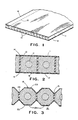
- the array of tubes disclosed in Figs. 1 and 2 comprise generally flat face panels 11 and 12 spaced apart and longitudinally partitioned into square tubes by flat partition strips 13 of uniform and equal width having longitudinal edge bonds 14 and 15 joined to panels 11 and 12.
- a suitable face panel material is Pellon style 2131 supplied by Pellon Corporation, 20 Industrial Avenue, Chelmsford, Massachusetts, as a felted fabric of staple fibers of polyester needled and stiffened with 20 grams per square meter of acrylic acid.
- a suitable partition material is a high density polyethylene film between 0.015 and 0.030 inch thick.
- Bonds are formed for battery purposes by applying heat and pressure through the face panels 11 and 12 while the longitudinal edges of strips of the partition material are maintained against the panels.
- the melting temperature of the face panel material should be sufficiently above the melting temperature of the partition material that a reasonable range of processing temperatures are available to heat the partition material to its melting temperature without melting the face panel material even when the heat is applied through the face panel.
- the bonds 14 and 15 are developed over a region within the fiber interstices of the face panels 11 and 12 of greater width than the thickness of the partitions 13 and extend into the fiber interstices through the thickness of the face panels.
- the partition edge is melted down about 0.030 inch along the longitudinal margin engaging the face panel to develop a bond over a band having a width of about 0.040 inch within the face panel and having corner fillets between the panel and partition for a 0.020 inch thick partition.
- the high density polyethylene melts at about 160°C (320°F) and the bonding temperature is about 165.56°C (330°F) where the polyester face panel fabric melts around 204.44°C (400°F).
- Battery plates are formed from the tubular array by conventional techniques involving plugging one end of the tube of an array, injecting active material 16 into the tubes and inserting electrode spines 17 into each tube as shown in Fig. 2. the active material is inserted as a thick paste.
- the ust of smooth film partitions facilitates the paste insertion.
- FIG. 3 An alternative form of tube array is shown in Fig. 3 wherein the fabric surface permeable to electrolyte and ionic flow is increased and channels for electrolyte flow in the battery plate stack are provided by employing a polygonal tube cross section 18 in a planar array 19.
- a longitudinally extending series of V grooves 21 are equally spaced across the width of each of face panels 22 and 23 with the length of the arm of each V and of the flat 24 between adjacent Vs being equal so that partitions 25 of that final width form equilateral octagons 18 as the tube cross sections when the V groove apexes are aligned across the thickness of the array.
- the face panels 22 and 23 can be formed over an anvil while the impregnated felted polyester fabric is heated to its softening temperature.
- the parallel longitudinal tubular arrays lend themselves to continuous and progressive fabrication from strip sheet stock although individual array fabrication can be practiced with simple tooling and processing.
- the basic fabricating step is the bond of the longitudinal edges of partition strips 13 or 25, as the case may be, to face panels 11 and 12 or 22 and 23 while maintaining the strips straight, parallel and normal to the general plane of the face panels.
- Individual arrays can be fabricated employing a partition support having spaced parallel slots of a width to reveive and constrain partition strips against buckling. Such support should have slot depths slightly less than the initial width of the partition strips to present above the slot walls that portion of each strip longitudinal edge which is to be incorported in the bond to the face panel.
- a face panel laid on the protruding strip edges can be bonded to those edges by applying sufficient heat to the exposed face panel surface to melt the edges and enough pressure to press the panel into those edges and enough pressure to press the panel into those edges while the opposite edges of the strips are restrained by the slot bottoms.
- the assembly can be inverted and rods or tines placed between the partitions to support them during the application of the second face panel.
- the exposed longitudinal edges of the partitions should be defined by the rod dimensions from the bonded face panel and should be the amount of material desired to be incorporated in the bond to the second face panel.
- Heat applied through the outer face to melt the partition edges and pressure to force the melted material into the outer face forms the second bond.
- the partition supports limit by their dimension along the partition widths the amount of displacement of the heated face panel and thereby the amount of partition material introduced into the bond.
- Fig. 4 shows an apparatus for a continuous and progressive formation of tubular arrays wherein coiled strip sheet stock is fed into the apparatus and arrays cut to length as for industrial storage battery plates, issue from the apparatus.
- Face panel fabric reels 31 and 32 supply sheet strips to first and second bonding stations 33 and 34. Strips of partion film from a reel 35 and film slitter 36 are fed to a strip orientor 37 and thence to the bonding stations 33 and 34 between the face panel fabric runs.
- a traction assembly 38 draws the bonded length of tubing array through the bonding stations and advances the leading end of the length into a flying cut-off station 39 which cuts battery plate lengths of tube array form the leading end.
- the tube array forming process illustrated in Fig. 4 involves bonding the upper longitudinal edge 41 of partition strips 42 to the upper face panel fabric 43 lower surface in bonding station 33 and bonding the lower longitudinal edge 44 of stripd 42 to the lower face panel fabric 45 upper surface in bonding station 34.
- Partition sheet film 46 is drawn from reel 35 through slitter 36 by driven pinch rollers 47 which are synchronized in their speed with the drives for the remaining elements of the system.
- the slitter 36 can be of the shear type involving a series of alternating discs of greater and lesser diameter on shaft and of a thickness corresponding to the width of the slit strips opposed by corresponding interdigitating discs on a second shaft where the disc peripherial speeds correspond to the lineal speed of the stock to be slit.
- the film partition strips 42 are maintained in alignment through the pinch rollers 47 and are turned ninety degrees around their lengths into the orientor 37.
- the partition strip orientor 37 is made up of a group of tines or rods 48 arranged as tines spaced about the thickness of the partition plastic film to provide closely fitting guide slots 49 for the partition strips through bonding stations 33 and 34.
- the tines 48 are of a constant width which defines the width of the tubes formed around them and of a varying height to control the bonding of the strip partition edges as they are melted into the face panel fabric.
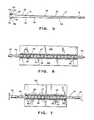
- Tines 48 as viewed in Fig. 5 have an initial portion 49 of constant cross section along a length 50 preceding the bonding station 33.
- Section 50 has a height of at least the width of the partition strips as they are slit from sheet 46.
- Tine section 51 which registers with the bonding station 33 has a tapered height which reduces along the direction of material flow so that the heater 52 pressed toward the upper 53 of section 51 approaches and engages the partition upper edges 41 while the back up 54 supporting the untapered bottom 55 of the tines support the lower longitudinal edges 44 of the strips.
- the taper in section 51 of the tines will reduce from a dimension from the edge adjacent the back up surface 54 somewhat greater than the strip width at the slitter end to the strip width less the 0.030 inch to be melted into the bond at the bonding station exit. end.
- the tines 48 are of uniform cross section along a region 56 until they enter the second bonding region of station 34 at section 57.
- the lower longitudinal edges 44 are melted into the facing fabric 45 on the botton of the run and therefore the bottom face 58 of the tines are tapered upward to effect the progressive application of heat and pressure on the edges 44 as they are advanced.
- the upper surface 59 is parallel to the initial upper surface of portion 50 and set downward therefrom at least the amount of the partition melt down in the first bonding station 51, 0.030 inch in the example, while the lower surface 58 is tapered upward toward its downstream end the amount of the bonding melt down at the partition edges 4, 0.030 inch in the example.
- the tines 48 have cross sections corresponding to the interior of the tubes formed around them.
- An extension to maintain dimensions until the assembly has been stabilized by cooling is represented in this section 61.
- the partitions are splayed adjacent the face panels to form a fillet into the bond; therefore the tines 48 are chamfered at their corners to accommodate those fillets.
- Tines 48 can function as orientors of the partition strips 42 after they pass through the nip of the pinch rollers 47. Rollers 47 maintain the partition material film sheet 46 under tension through slitter 36 since a suitable drag force is maintained on supply reel 35.
- the partition strips have their major faces maintained in a common plane through the pinch rollers 47.
- Tines 48 float in the clamp bars 62 along the transverse dimension of the panel to accommodate the variations in thickness of the film 46 since any such variation is multiplied by the number of partitions across the array and can be significant in the control of the apparatus.
- the tines 48 can be of uniform height in the bonding stations. That is, they can be of a height less than the width of the partition strips 42 an amount equal to the desired depth of partition material to be fused into the face panel over the entire length of the bonding stations.
- the tine height could be 0.030 inch less than the slit width of strips 42 and in station 34 the tine height could be stepped down to 0.060 inch less than the slit width to dictate a melt in of 0.030 inch into each of the upper and lower face panels 43 and 45.
- Bonding station 33 comprises an upper heater 52 and a backup plater 54 each of which are arranged to bear indirectly through the friction reducing belts 68 and 69 against the outer surface of face panel sheets 43 and 45 respectively.
- Back-up plate 54 can be fixedly mounted on the apparatus frame and heater 52 is mounted for movement normal to the major face of sheet 43 to inpose pressure through that sheet onto the upper longitudinal edges 41 of the partitions 42.
- Heater 52 can be a casing lying between the upper and lower run of belt 68 and housing a cast iron block 75 having suitable cavities 76 to receive electrical heater cartidges 77. In a horizontal run of the strip stock, the gravitational forces on block 75 apply adequate pressure to effect the desired bond if the block weighs about five hundred pounds and is applied to an array of fifteen tubes employing sixteen partitions.
- Cooling can be applied to the upper face panel 43 after it leaves the bonding station 33 and before it is passed into bonding station 34 to acccelerate the solidification of the melted partion material.
- the lower face panel material 45 is bonded to the partitions by an arrangement of parts inverted from those of station 33.
- Back-up plate 79 bears on the inner face of the bottom run of belt 81 trained over rollers 82 and 83.
- Heater block 84 bears on the upper run of belt 85 trained over rollers 86 and 87.
- Back-up plate 79 is fixed to the apparatus frame. Heater block 84 is biased upward toward the lower face of face panel sheet 45 by pneumatic cylinders 88. Electric heater cartridges 89 are provided in heater block 84.
- the bonded tubular array is pressed through a cooling station 91 where the bonds are set up by jets of cooling air prior to the application of traction pressure to the array in traction assembly 38.
- the upper and lower face panel runs and the partitions are driven through the apparatus at a constant speed by snychronized drives for rollers 47, belts 68 and 69, belts 81 and 85, traction belts 92 and 93 and the cut-off trolley 90 of the flying cut-off station 39.
- One arrangement is to drive all elements from a common drive motor 94 through a drive 95 having an output shaft 96 to lower traction assembly drive roller 97 and through gears 98 and 99 to upper traction assembly drive roller 101. roller 101.
- Upper traction roller 102 driven by upper traction belt 92, drives belt 103 which drives roller 82 for upper bonding station 104 to roller 72 for bonding station belt 68 and roller 71.
- the lower face panel material 45 is driven through belt 93 which drives roller 105 to belt 106 which drives roller 87 in the lower bonding station to drive belt 85 and roller 86 which drives belt 107 to roller 74 of the upper bonding station to drive belt 69 and roller 73 which drives belt 108 to lower pinch roll 109 and through gears 111 and 112 to upper pinch roll 113.
- the relatively rigid board like tube array is compressed between and frictionally engaged by traction surfaces of belts 92 and 93 which may be of elastomeric material to provide effective traction to pull the strip material through the orientor 37 and the bonding stations 33 and 34.
- the array strip advances from traction assembly 38 to the table 114 to cut-off trolley 90 where it is cut to the desired length on the fly.
- the table 114 is slotted at 115 to pass a cut-off wheel 116 driven by motor 117 and arranged to traverse the trolley on ways 118 when driven by pneumatic cylinder 119.
- Trolley 90 is mounted on ways 121 to move along the feed path of the strip material.
- the tubular array of a plate casing is cut off in lengths of about eighteen inches although such applications are commonly in lengths of from nine to twenty four inches and the apparatus can be arranged to produce such lengths.
- the apparatus for producing an array of parallel tubes as shown in Figs. 1, 2 and 3 generally comprises means to support a plurality of partition strips 13 or 42, each having parallel longitudinal edges 41 and 44 bordering opposed major faces and of a stiff sheet material.
- the strip support means in the example being an array of tines 48 having spaced sides which are straight and parallel to define slots 49 which maintain the major faces of the strips parallel and their longitudinal edges parallel.
- Means to support a facing sheet against a longitudinal edge of each strip 42, the upper edge in the drawings, in the form of the surface of an element, either the heater block or the belt 68, bearing against the facing sheet is provided while the sheet is in the bonding station 33.
- the facing sheet is of a material which has a higher melting temperature than the partition strip material
- the longitudinal edge of the partition material is melted down and the face material is displaced toward the strips by means to apply heat and pressure to the face of the first facing sheet opposite the face adjacent the first edges of the partition strips at a temperature above the partition strip melting temperature and below the facing sheet melting temperature.
- the degree of such displacement is controlled by the tine thickness which in at least a portion of the bonding region 33 has a thickness less than the width of the major faces of the strips it is adapted to support an amount equal to the depth of melting of the strip first longitudinal edge, 0.030 inch in the example.
- a second support for the partition strips maintains their major faces parallel and their second longitudinal edges parallel.
- This second support can also be an array of tines and advantageously, can be extensions of the tines providing the first support for the partition strips.
- Means to support the second facing sheet against the second longitudinal edges 44 of the partition strips 42 establishes a relationship between that sheet and the strips for bonding them by means to applying heat and pressure to the face of the second facing sheet opposite the face of that sheet adjacent the second longitudinal edge of the strips.
- the second strip could be of a material having a third melting temperature above the melting temperature of the partition sheet material, and the second heating means could be heated to a temperature above the melting temperature of the partition material and below that third melting temperature to effect the fusion bond of the sheet to the partitions.
- the support in the second bonding region can be an array of tines having at least a portion of the length of each tine of a thickness less than the width of the major face of the partition strip it is adapted to support an amount equal to the depth of the strip second longitudinal edge to be melted into the bond.
- the tines can be tapered in the bonding stations 33 and 34 to gradually melt in the partition material where the partitions and facing sheets are advanced longitudinally and progressively and precise control of each bond melt depth can be achieved where the bond stations are in tandem along the advance direction so that each partition edge is bonded individually and separately.
- the partition support means, the face panel support means and the heating and pressing means cooperate to form first and second bonding stations which are spaced along the path of longitudinal advance of the strips and sheet so the second station elements are downstream of the first.
- An alignment of the elements of the apparatus along the direction of advance of the sheets and partition strips enables continuos processing from the strip supply reel supports to the cooling station and the cut-off.
- the cut-off includes a cut-off wheel and tube array support table which are reciprocable and synchronized in the advance direction with the array advance.
- Heater block 125 differs from block 75 in that it is in direct contact with face panel strip 43 in registry with the grooves between tines 48 in which partition strips 42 are retained.
- the contact regions 126 extend in the direction of travel of the face panel and partition strips and the block is relieved as by intermediate grooves 127 to reduce the contact area between the block and fabric thereby reducing the friction developed for a given bonding pressure for the block contact.
- a smooth back-up plate 128 has been shown engaging lower face panel 45 although it could be relieved between the partitions in much the same manner as heater bock 125 if friction forces required reduction.
- tubular array provided as described above might be used for other than the casings of storage battery plates and that the facing and partition materials might be chosen to be of materials other than the polyester and lower melting polyethylene or polyolefine discussed.
- specific material driving and heating structures could be modified, for example, by heating both longitudinal edges of the partition strips simultaneously to bond both faces in a single bonding station pass, with some loss of pressure and bonding penetration control, or by introducing one of the facing panel sheet stock runs into the second bonding station 34 after the partitions have been bonded to the opposite panel.
- the partitions could be presented to the apparatus as strips rather than in sheet form. Traction surfaces could be provided on the friction reducing belts or as shown in Fig. 7 the belts could be eliminated.
- the bonds can be made between the longitudinal edges and the face panels by applying a softening solvent to the edges or by applying adhesive although care must be exercised to avoid producing softened material or adhesive on the tines.
- the present disclosure is to be read as illustrative and not in a restrictive sense.
Landscapes
- Engineering & Computer Science (AREA)
- Mechanical Engineering (AREA)
- Physics & Mathematics (AREA)
- Thermal Sciences (AREA)
- Chemical Kinetics & Catalysis (AREA)
- Chemical & Material Sciences (AREA)
- Textile Engineering (AREA)
- Electrochemistry (AREA)
- General Chemical & Material Sciences (AREA)
- Fluid Mechanics (AREA)
- Cell Separators (AREA)
- Cell Electrode Carriers And Collectors (AREA)
- Lining Or Joining Of Plastics Or The Like (AREA)
Abstract
A tubelet panel of fabric sheets and parallel, continuous film, partition strips (13) normal to the face sheets (11, 12) and having their longitudinal edges (14, 15) fused into the fabric of the face sheets (11, 12) is formed by thermal fusion by applying heat and pressure to the outer surfaces of the face sheets (11, 12) in the regions in registry with the partition edges (14, 15). The partition material is chosen to have a lower melting temperature than the face sheet (11, 12) material and the applied heat is at a temperature above the melting temperature of the partition (13) material and below the melting temperature of the face (11, 12) sheet material. Parallel tines spaced about the thickness of the partition strips (13) guide the strips through a bonding region for one face sheet followed along the path of advance of the face materials and the partition strips (13) by a bonding station for the other face sheet and are of a thickness which varies as the bonds are progressively formed to limit the displacement of heating means against the partition edges to the amount of material of the edges to be fused into the bond.
Adjuncts include feeding of the face (11, 12) sheet material and partition material as strip stock, as from a reel, slitting the partition material to the desired strip (13) width in line, and cutting off lengths of the tubelet panel as for battery plate casing lengths.
Adjuncts include feeding of the face (11, 12) sheet material and partition material as strip stock, as from a reel, slitting the partition material to the desired strip (13) width in line, and cutting off lengths of the tubelet panel as for battery plate casing lengths.
Description
- This invention relates to panels made up of arrays of parallel contiguous, longitudinal tubes in side-by-side relationship, to such panels suitable for electrode casings for plates for storage batteries and to methods of and apparatus for the manufacture of such panels.
- Heretofore it has been known to form storage battery electrodes as planar arrays of straight parallel tubes of electrical insulating materials which are resistant to the adverse effects of battery electrolytes and the electrochemical reactions which occur in batteries.
Electrodes are formed by filling the tubes with active electrode material, inserting metal rods along the central axes of the tubes and electrically interconnecting the rods with a cross bar. In lead batteries, the rods and cross bars are predominantly of lead and the active material is the lead and lead oxide utilized for the positive and negative electrodes of such batteries. U.S. patent 1,243,371 of October 16, 1917, to T.A. Willard disclosed an array of porous tubes for storage batteries made up of two plates, each having a plurality of right-circular semicylinders and made from sheets of rubber and porous material formed with minute pores uniformly distributed and extending through the sheets. - The plates were joined together as by vulcanizing. An array of polygonal shaped tubes joined as panels by intermediate webs are disclosed for positive and negative battery electrodes in U.S. patent 1,409,895 of March 12, 1922, to Knoblock et al. The array of tubes for the casings are made of a porous nonconducting material, preferably earthenware. Galloway, U.S. patent 2,266,546 of December 16, 1941, disclosed a storage battery plate mad up of a row of pencils of active material on metal spines connected by a metal bar and surrounded by a band of acid resistant fabric seamed between the individual pencils to form connected sheaths of circular cross section.
In U.S. patent 2,343,970 of March 14, 1944, Galloway proposed a strip of thermoplastic cement between the individual pencils and the confronting faces of the fabric bonded by heat and pressure applied through the fabric. Brennan, U.S. patent 2,985,701, joined fabric face panels with overlaying plastic grids on the outer faces of the fabric and joined by internal pins extending through the fabric to form the separate tubes of an electrode array. - Square cross section tubes in parallel array were proposed in Martin, U.S. patent 2,755,328 of July 17, 1956, where two channel sections of molded plastic having parallel slots through their walls were cemented together and then joined as a flat panel array to form electrode casings. Injection molded polystyrene was proposed as a suitable material resistant to sulphuric acid.
- Braided or knitted tubes of polyvinyl esters and other acrylic resins and polystyrene were suggested as envelopes for arrays of pencils of active material on lead spines in Kershaw, U.S. patent 2,176,428 of October 17, 1939. Graff, U.S. patent 2,350,752 of June 6, 1944, shows an array of tubes for encasing pencils for electrodes made of woven fabric of glass or synthetic resin where the fabric layers of a sheath are interwoven by weft threads between the pencils. A similar arrangement coupled with thermally shrinking the interwoven fabric onto the pencils is proposed in Boriolo, U.S. patent 2,972,000 of February, 1961. Lindholm et al., U.S. patent 4,374,908 of February 22, 1983, employs electrolyte-permeable tube casings of oval cross section from a woven sock of glass fiber and a perforated outer housing of plastic in a parallel flat panel array for battery electrodes and spacer ribs of polyethylene or polystyrene between the tubes and separator sheets.
- Non-woven fabric has also been proposed for various tubular casings for storage battery electrodes in Fahrbach U.S. patent 3,462,305 of August 19, 1969, where superposed needled batts of intertangled textile fibers are sewn with rows of stitching at spaced intervals to join the batts and form tubes into which are inserted forms to hold the tube shape while the fabric is treated with a hardener. Hoffman et al. U.S. patent 4,140,839 of February 20, 1979, addresses the problem of withstanding expansion forces of the electrodes encased by non-woven textile sheet material sewn into the tubelets by reinforcing the sheet with a woven or laid fabric.
- A continuous and progressive process for forming tubular casings for battery electrodes is disclosed in Sundberg U.S. patent 4,276,359 of June 30, 1981. Arrays of parallel tubes of fabric are formed by overlaying two lengths of felted or woven fibers of glass or plastic such as polyester, propathene, or other acid proof plastic, applying plastic net or a highly perforated plastic sheet against the outer sides of the sheets. The layered structure is face bonded along spaced bands extending longitudinally of the strip sheets by the application of heat and pressure on those bands.
- Where glass or polyester is employed, tapes of polyethylene or propylene are face bonded at the bands by the heat and pressure. Subsequent processing is required to to open the unbonded regions or flat tubes between the bond bands by insertion of mandrels. It is suggested that the final tube form for introduction of active material and electrode spines can be achieved with heat and forming tools either internal or outside of the sandwiched strucutre for certain materials or the material when formed in that manner can be impregnated with hardening material.
- It is an object of the present invention to improve the tube panel structure for battery electrode casings, the method of manufacture of such structures and the manfacturing apparatus. More particularly, objects of this invention are to improve the tube casings, to reduce their cost of materials and fabrication, to simplify their manufacture, and to reduce the number of elements and processing steps in their manufacture.
- In accordance with the above objects one feature or this invention is a tube array comprising a pair of opposed generally planar parallel face panels of a first sheet material joined by a plurality of parallel partitions of a secon material perpendicular to the general plane of the panels and edge bonded thereto. The face panels can be of a fabric and can be preformed parallel to the partitions whereby the tubes can be of polygonal cross section such as hexagonal or octagonal. Where the face panels are flat, the cross section of the tubes is reactangular.
- In an electrode casing application, the face panels can be of felted or woven fibers of glass or plastic which is inert to the materials and processes within a battery and is porous to the electrolyte and ionic flow while the partitions can be of film providing smooth surfaces for facili tating the introduction of active material into the tubes. An advantageous combination is face panels of felted polyester fibers needled and impregnated with a stiffener such as acrylic acid and partitions of polyethylene or polyolefine film of a thickness to form a rigid array yet suitable to be fed to the forming apparatus from a coiled supply.
- Another feature is the thermal fusion under pressure of the partition edges into the face panel fiber interstices to provide a strong bond of a width greater than the partition thickness with withstands the stresses imposed in the expansion of the electrode active material during battery operation.
- Continuous formation of tube arrays from strip stock is accomplished in a single pass with apparatus which feeds the sheet material of the facing panels and partitions from rolls, slits the partition sheet to appropriate width, orients the facing and partitions for bonding, bonds the partitions along their longitudinal edges to the respective facing panels and cuts off appropriate lengths of the formed tubular array as it issues from the forming region. Where longitudinal ridges are desired, as for formation of tubes of polygonal cross section, a forming section for the face panel sheets can precede the introduction of those sheets into the bonding stations. Thus finished tube arrays are formed in a single pass.
- Another feature involves control of the extent of the bond of the longitudinal edges of the partition strips in the face panels by means of internal guides cooperating with the means applying heat and pressure to limit the relative displacement of the partition edges and face panels during the interval those edges are molten or softened. An array of tines extend longitudinally of the feeding path for the facing and partition materials are spaced to confine the faces of the partitions perpendicular to the face panels in slots between adjacent tines. The width of the tines and their transverse spacing is maintained along their lengths while their thickness is tapered in the bonding stations so that the longitudinal edges are progressively advanced into the face panels by opposed surfaces imposing pressure at each side of the tine defined slots.
- The above and additional objects and features of this invention will be appreciated more fully from the following detailed description when read with reference to the accompanying drawings in which:
- Fig. 1 is a fragmentary view of an array of square tubular casings for an electrode of a storage battery according to this invention;
- Fig. 2 is an enlarged fragment of a cross section of the array of Fig. 1 with active material and electrode spines in place within the tubes;
- Fig. 3 is a cross section similar to Fig. 2 of tubes of octagonal cross section;
- Fig 4. is a schematic perspective view of a machine according to this invention for forming the array of square tubes in a flat panel as shown in Fig. 1;
- Fig. 5 is a side elevational view of a partition guiding tine for the apparatus of Fig. 4;
- Fig. 6 is a sectioned view of a bonding station taken at lines 6-6 of Fig. 4; and
- Fig. 7 is a sectioned view corresponding to Fig. 6 for an alternative bonding station arrangement.
- The array of tubes disclosed in Figs. 1 and 2 comprise generally
flat face panels flat partition strips 13 of uniform and equal width havinglongitudinal edge bonds panels - Bonds are formed for battery purposes by applying heat and pressure through the
face panels - In practice with the exemplary materials the
bonds face panels partitions 13 and extend into the fiber interstices through the thickness of the face panels. Thus with face panels of about 0.010 inch thickness, the partition edge is melted down about 0.030 inch along the longitudinal margin engaging the face panel to develop a bond over a band having a width of about 0.040 inch within the face panel and having corner fillets between the panel and partition for a 0.020 inch thick partition. The high density polyethylene melts at about 160°C (320°F) and the bonding temperature is about 165.56°C (330°F) where the polyester face panel fabric melts around 204.44°C (400°F). - Battery plates are formed from the tubular array by conventional techniques involving plugging one end of the tube of an array, injecting
active material 16 into the tubes and insertingelectrode spines 17 into each tube as shown in Fig. 2. the active material is inserted as a thick paste. The ust of smooth film partitions facilitates the paste insertion. - An alternative form of tube array is shown in Fig. 3 wherein the fabric surface permeable to electrolyte and ionic flow is increased and channels for electrolyte flow in the battery plate stack are provided by employing a polygonal
tube cross section 18 in aplanar array 19. A longitudinally extending series ofV grooves 21 are equally spaced across the width of each offace panels 22 and 23 with the length of the arm of each V and of the flat 24 between adjacent Vs being equal so thatpartitions 25 of that final width formequilateral octagons 18 as the tube cross sections when the V groove apexes are aligned across the thickness of the array. Theface panels 22 and 23 can be formed over an anvil while the impregnated felted polyester fabric is heated to its softening temperature. In the continuous tube forming process to be discussed, such surface forming can be accomplished in line with the other fabricating steps. However, the surfaces of the bonding regions should conform to the grooved surface ofpanels 22 and 23, at least to the extent of applying bonding heat to the panel surface bands in registry with the partition edges. - The parallel longitudinal tubular arrays lend themselves to continuous and progressive fabrication from strip sheet stock although individual array fabrication can be practiced with simple tooling and processing. The basic fabricating step is the bond of the longitudinal edges of partition strips 13 or 25, as the case may be, to face
panels - Fig. 4 shows an apparatus for a continuous and progressive formation of tubular arrays wherein coiled strip sheet stock is fed into the aparatus and arrays cut to length as for industrial storage battery plates, issue from the apparatus. Face
panel fabric reels second bonding stations reel 35 andfilm slitter 36 are fed to astrip orientor 37 and thence to thebonding stations traction assembly 38 draws the bonded length of tubing array through the bonding stations and advances the leading end of the length into a flying cut-off station 39 which cuts battery plate lengths of tube array form the leading end. - The tube array forming process illustrated in Fig. 4 involves bonding the upper
longitudinal edge 41 of partition strips 42 to the upperface panel fabric 43 lower surface inbonding station 33 and bonding the lowerlongitudinal edge 44 ofstripd 42 to the lowerface panel fabric 45 upper surface inbonding station 34.Partition sheet film 46 is drawn fromreel 35 throughslitter 36 by drivenpinch rollers 47 which are synchronized in their speed with the drives for the remaining elements of the system. Theslitter 36 can be of the shear type involving a series of alternating discs of greater and lesser diameter on shaft and of a thickness corresponding to the width of the slit strips opposed by corresponding interdigitating discs on a second shaft where the disc peripherial speeds correspond to the lineal speed of the stock to be slit. The film partition strips 42 are maintained in alignment through thepinch rollers 47 and are turned ninety degrees around their lengths into theorientor 37. - As best seen in Figs. 5 and 6 the
partition strip orientor 37 is made up of a group of tines orrods 48 arranged as tines spaced about the thickness of the partition plastic film to provide closelyfitting guide slots 49 for the partition strips throughbonding stations tines 48 are of a constant width which defines the width of the tubes formed around them and of a varying height to control the bonding of the strip partition edges as they are melted into the face panel fabric. - The bond between the
upper face panel 43 and the upperlongitudinal edges 41 of partition strips 42 is progressively developed inbonding station 33 by progressively meltingedges 41 and pressing their melted portions intopanel 43.Tines 48 as viewed in Fig. 5 have aninitial portion 49 of constant cross section along alength 50 preceding thebonding station 33.Section 50 has a height of at least the width of the partition strips as they are slit fromsheet 46.Tine section 51 which registers with thebonding station 33 has a tapered height which reduces along the direction of material flow so that theheater 52 pressed toward the upper 53 ofsection 51 approaches and engages the partitionupper edges 41 while the back up 54 supporting the untapered bottom 55 of the tines support the lowerlongitudinal edges 44 of the strips. Thus, in the case of a melt down of 0.030 inch of edge material, the taper insection 51 of the tines will reduce from a dimension from the edge adjacent the back upsurface 54 somewhat greater than the strip width at the slitter end to the strip width less the 0.030 inch to be melted into the bond at the bonding station exit. end. - Following the first bonding region, the
tines 48 are of uniform cross section along aregion 56 until they enter the second bonding region ofstation 34 atsection 57. In this bonding region the lowerlongitudinal edges 44 are melted into the facingfabric 45 on the botton of the run and therefore thebottom face 58 of the tines are tapered upward to effect the progressive application of heat and pressure on theedges 44 as they are advanced. Thus insection 57 oftine 48 theupper surface 59 is parallel to the initial upper surface ofportion 50 and set downward therefrom at least the amount of the partition melt down in thefirst bonding station 51, 0.030 inch in the example, while thelower surface 58 is tapered upward toward its downstream end the amount of the bonding melt down at the partition edges 4, 0.030 inch in the example. Beyond thesecond bonding region 57 thetines 48 have cross sections corresponding to the interior of the tubes formed around them. An extension to maintain dimensions until the assembly has been stabilized by cooling is represented in thissection 61. As shown in Figs. 1 and 2 the partitions are splayed adjacent the face panels to form a fillet into the bond; therefore thetines 48 are chamfered at their corners to accommodate those fillets.
Tines 48 can function as orientors of the partition strips 42 after they pass through the nip of thepinch rollers 47.Rollers 47 maintain the partitionmaterial film sheet 46 under tension throughslitter 36 since a suitable drag force is maintained onsupply reel 35. The partition strips have their major faces maintained in a common plane through thepinch rollers 47. Down stream ofrollers 47 the strips are twisted around their longitudinal axes and fed between thetines 48 clamped at their leading ends between channeled clamp bars 62 the channel sides of which fit overcleats 63 transverse of the upper and lower faces of thetines 48 at the leading end ofsection 49.Tines 48 float in the clamp bars 62 along the transverse dimension of the panel to accommodate the variations in thickness of thefilm 46 since any such variation is multiplied by the number of partitions across the array and can be significant in the control of the apparatus. Side pressure is maintained on the tines to accomodate the partition thickness variations while maintaining uniform confining pressure on the partitions through the bonding and forming stations by side pressure bare 64 andpneumatic cylinders 65 which are secured to the machine frame (not shown) and are arranged to impose about fifty pounds side thrust on the bars. - Alternatively, the
tines 48 can be of uniform height in the bonding stations. That is, they can be of a height less than the width of the partition strips 42 an amount equal to the desired depth of partition material to be fused into the face panel over the entire length of the bonding stations. Instation 33 the tine height could be 0.030 inch less than the slit width ofstrips 42 and instation 34 the tine height could be stepped down to 0.060 inch less than the slit width to dictate a melt in of 0.030 inch into each of the upper andlower face panels - Down stream of the tine clamp bars 62 the face panel sheet stock is fed into engagement with the upper 66 and lower 67 surfaces of the
tines 48 and in sliding engagement therewith. This relationship is maintained throughout the balance of the length of the tines. In order to minimize the frictional force imposed on the face panels inbonding stations flexible surfaces fabric panels flexible belts station 33 to move in the direction of advance of thepanel sheet stock rollers belt 68 androllers belt 69. -
Bonding station 33 comprises anupper heater 52 and abackup plater 54 each of which are arranged to bear indirectly through thefriction reducing belts face panel sheets up plate 54 can be fixedly mounted on the apparatus frame andheater 52 is mounted for movement normal to the major face ofsheet 43 to inpose pressure through that sheet onto the upperlongitudinal edges 41 of thepartitions 42.Heater 52 can be a casing lying between the upper and lower run ofbelt 68 and housing acast iron block 75 havingsuitable cavities 76 to receive electrical heater cartidges 77. In a horizontal run of the strip stock, the gravitational forces onblock 75 apply adequate pressure to effect the desired bond if the block weighs about five hundred pounds and is applied to an array of fifteen tubes employing sixteen partitions. - Cooling can be applied to the
upper face panel 43 after it leaves thebonding station 33 and before it is passed intobonding station 34 to acccelerate the solidification of the melted partion material. Inbonding station 34 the lowerface panel material 45 is bonded to the partitions by an arrangement of parts inverted from those ofstation 33. Back-up plate 79 bears on the inner face of the bottom run ofbelt 81 trained overrollers Heater block 84 bears on the upper run ofbelt 85 trained overrollers up plate 79 is fixed to the apparatus frame.Heater block 84 is biased upward toward the lower face offace panel sheet 45 bypneumatic cylinders 88. Electric heater cartridges 89 are provided inheater block 84. - The bonded tubular array is pressed through a
cooling station 91 where the bonds are set up by jets of cooling air prior to the application of traction pressure to the array intraction assembly 38. The upper and lower face panel runs and the partitions are driven through the apparatus at a constant speed by snychronized drives forrollers 47,belts belts traction belts trolley 90 of the flying cut-off station 39. One arrangement is to drive all elements from acommon drive motor 94 through adrive 95 having anoutput shaft 96 to lower traction assembly drive roller 97 and throughgears assembly drive roller 101.
roller 101. The balance of the rollers are coupled through the belts engaging the work strip and drive belts. Upper traction roller 102, driven byupper traction belt 92, drivesbelt 103 which drivesroller 82 forupper bonding station 104 toroller 72 forbonding station belt 68 androller 71. The lowerface panel material 45 is driven throughbelt 93 which drivesroller 105 to belt 106 which drivesroller 87 in the lower bonding station to drivebelt 85 androller 86 which drivesbelt 107 toroller 74 of the upper bonding station to drivebelt 69 androller 73 which drivesbelt 108 tolower pinch roll 109 and throughgears 111 and 112 toupper pinch roll 113. - The relatively rigid board like tube array is compressed between and frictionally engaged by traction surfaces of
belts orientor 37 and thebonding stations traction assembly 38 to the table 114 to cut-offtrolley 90 where it is cut to the desired length on the fly. The table 114 is slotted at 115 to pass a cut-off wheel 116 driven bymotor 117 and arranged to traverse the trolley onways 118 when driven bypneumatic cylinder 119.Trolley 90 is mounted onways 121 to move along the feed path of the strip material. It is driven in the feed direction at the speed the strip issued from the traction assembly by a reversingball screw drive 122, driven bybelt 123 from output shaft 124 fromdrive 95. Typically, for industrial battery plate casings, the tubular array of a plate casing is cut off in lengths of about eighteen inches although such applications are commonly in lengths of from nine to twenty four inches and the apparatus can be arranged to produce such lengths. - The apparatus for producing an array of parallel tubes as shown in Figs. 1, 2 and 3 generally comprises means to support a plurality of partition strips 13 or 42, each having parallel
longitudinal edges tines 48 having spaced sides which are straight and parallel to defineslots 49 which maintain the major faces of the strips parallel and their longitudinal edges parallel. Means to support a facing sheet against a longitudinal edge of eachstrip 42, the upper edge in the drawings, in the form of the surface of an element, either the heater block or thebelt 68, bearing against the facing sheet is provided while the sheet is in thebonding station 33. Since the facing sheet is of a material which has a higher melting temperature than the partition strip material, the longitudinal edge of the partition material is melted down and the face material is displaced toward the strips by means to apply heat and pressure to the face of the first facing sheet opposite the face adjacent the first edges of the partition strips at a temperature above the partition strip melting temperature and below the facing sheet melting temperature. The degree of such displacement is controlled by the tine thickness which in at least a portion of thebonding region 33 has a thickness less than the width of the major faces of the strips it is adapted to support an amount equal to the depth of melting of the strip first longitudinal edge, 0.030 inch in the example. A second support for the partition strips maintains their major faces parallel and their second longitudinal edges parallel. This second support can also be an array of tines and advantageously, can be extensions of the tines providing the first support for the partition strips. Means to support the second facing sheet against the secondlongitudinal edges 44 of the partition strips 42 establishes a relationship between that sheet and the strips for bonding them by means to applying heat and pressure to the face of the second facing sheet opposite the face of that sheet adjacent the second longitudinal edge of the strips. While the first and second facing strips have been disclosed to be of the same material, it is to be appreciated that the second strip could be of a material having a third melting temperature above the melting temperature of the partition sheet material, and the second heating means could be heated to a temperature above the melting temperature of the partition material and below that third melting temperature to effect the fusion bond of the sheet to the partitions. Again the support in the second bonding region can be an array of tines having at least a portion of the length of each tine of a thickness less than the width of the major face of the partition strip it is adapted to support an amount equal to the depth of the strip second longitudinal edge to be melted into the bond. The tines can be tapered in thebonding stations - An alternative form of bonding station wherein the friction reducing belts have been eliminated, at least between the heater block and the face panel to which the partition is being bonded, to enhance the concentration of applied heat at the longitudinal bands in which bonds are to be formed as shown in Fig. 7.
Heater block 125 differs fromblock 75 in that it is in direct contact withface panel strip 43 in registry with the grooves betweentines 48 in which partition strips 42 are retained. Thecontact regions 126 extend in the direction of travel of the face panel and partition strips and the block is relieved as byintermediate grooves 127 to reduce the contact area between the block and fabric thereby reducing the friction developed for a given bonding pressure for the block contact. A smooth back-up plate 128 has been shown engaginglower face panel 45 although it could be relieved between the partitions in much the same manner asheater bock 125 if friction forces required reduction. - It is to be understood that the tubular array provided as described above might be used for other than the casings of storage battery plates and that the facing and partition materials might be chosen to be of materials other than the polyester and lower melting polyethylene or polyolefine discussed. Further, the specific material driving and heating structures could be modified, for example, by heating both longitudinal edges of the partition strips simultaneously to bond both faces in a single bonding station pass, with some loss of pressure and bonding penetration control, or by introducing one of the facing panel sheet stock runs into the
second bonding station 34 after the partitions have been bonded to the opposite panel. The partitions could be presented to the apparatus as strips rather than in sheet form. Traction surfaces could be provided on the friction reducing belts or as shown in Fig. 7 the belts could be eliminated. While it is advantageous in battery applications to avoid introduction of bonding compositions to the structure, the bonds can be made between the longitudinal edges and the face panels by applying a softening solvent to the edges or by applying adhesive although care must be exercised to avoid producing softened material or adhesive on the tines. Thus the invention lends itself to variations and it is to be appreciated that the present disclosure is to be read as illustrative and not in a restrictive sense.
Claims (37)
1. A tubular casing for an electrode for batteries comprising:
a pair of spaced porous outer panels of electrolyte-resistant, fibrous fabric;
a plurality of electrolyte-resistant, parallel strips having their major faces perpendicularto and extending between said outer panels; and
fusion bonds between the longitudinal margins of said strips and said outer panels.
a pair of spaced porous outer panels of electrolyte-resistant, fibrous fabric;
a plurality of electrolyte-resistant, parallel strips having their major faces perpendicularto and extending between said outer panels; and
fusion bonds between the longitudinal margins of said strips and said outer panels.
2. A tubular casing according to claim 1 wherein said spaced outer panels are essentially planar and parallel, and said parallel strips are of uniform width.
3. A tubular casing according to claim 1 wherein said fusion bonds are of the material of said strips fused into the interstices of the fibrous fabric of said outer panels.
4. A tubular casing according to claim 1 wherein said outer panels are rectangular and are formed with longitudinal corrugations, and said strips are bonded to the troughs of the corruglations.
A tubular casing according to claim 1 wherein said outer panels are rectangular and are formed with regularly spaced V grooves having the apexes of the V grooves on opposing panels aligned acroos the space between the panels and having said strips bonded to the aligned apexes of opposing panels.
6. A tubular casing according to claim 1 wherein said strips are of a smooth surfaced film material.
7. The method of forming tubular casings for electrodes for storage batteries comprising;
bonding a first longitudinal edge of a plurality of partition strips of electrolyte-resistant material to the face of a first sheet of porous electrolyte-resistant material with the major faces of the strips perpendicular to the sheet; and
bonding the longitudinal edge opposite the first edge of each of the plurality of strips to the face of a second sheet of porous electrolyte-resistant material.
bonding a first longitudinal edge of a plurality of partition strips of electrolyte-resistant material to the face of a first sheet of porous electrolyte-resistant material with the major faces of the strips perpendicular to the sheet; and
bonding the longitudinal edge opposite the first edge of each of the plurality of strips to the face of a second sheet of porous electrolyte-resistant material.
8. The method according to claim 7 wherein the first and second sheet are of fabric of a material having a first melting temperature and the partition strips are of a material having a lower melting temperature than said first melting temperature including the step of heating the strip edges above the lower melting temperature and below the first melting temperature to fuse the strip edges into the fabric of the sheets.
9. The method according to claim 8 including the step of pressing the heated edges of the partition strips into the fabric of the sheets.
10. The method according to claim 8 wherein heat is applied through a sheet to heat and fuse the strip edges into the sheet.
11. The method according to claim 7 including:
supporting each strip with its major face perpendicular to the sheet between elements having adjacent surfaces spaced slightly greater than the thickness of the strip material while bonding the longitudinal edge of the strip to the sheet.
supporting each strip with its major face perpendicular to the sheet between elements having adjacent surfaces spaced slightly greater than the thickness of the strip material while bonding the longitudinal edge of the strip to the sheet.
12. The method according to claim 11 including;
applying pressure across the width of the strip while bonding the longitudinal edge of the strip to the sheet.
applying pressure across the width of the strip while bonding the longitudinal edge of the strip to the sheet.
13. The method according to claim 7 wherein the bonding steps and continuous and progressive comprising;
feeding a ribbon of the material of the first sheet lengthwise and in generally planar form to a bonding station;
feeding a plurality of partition strips of the material lengthwise to the bonding station along a path paralleling the feeding path for the first sheet;
orienting the partition strips to have their major faces perpendicular to the general plane of the first sheet with a first longitudinal edge in engagement with the first sheet while in the bonding station; and
feeding a ribbon of the material of the second sheet lengthwise and in generally planar form into engagement with a second longitudinal edge of said partition strips.
feeding a ribbon of the material of the first sheet lengthwise and in generally planar form to a bonding station;
feeding a plurality of partition strips of the material lengthwise to the bonding station along a path paralleling the feeding path for the first sheet;
orienting the partition strips to have their major faces perpendicular to the general plane of the first sheet with a first longitudinal edge in engagement with the first sheet while in the bonding station; and
feeding a ribbon of the material of the second sheet lengthwise and in generally planar form into engagement with a second longitudinal edge of said partition strips.
14. The method according to claim 13 including the steps of;
pressing the first longitudinal edge of the partition strips against the first sheet while in the bonding station;
and
pressing the second longitudinal edge of the partition strips against the second sheet during the step of bonding those edges to that sheet.
pressing the first longitudinal edge of the partition strips against the first sheet while in the bonding station;
and
pressing the second longitudinal edge of the partition strips against the second sheet during the step of bonding those edges to that sheet.
15. The method according to claim 13 including the steps of;
heating the first and second longitudinal edges of the partition strips during the steps bonding those edges to the respective first and second sheets.
heating the first and second longitudinal edges of the partition strips during the steps bonding those edges to the respective first and second sheets.
16. The method according to claim 13 including the step of;
confining the partition strips between guides to orient those strips perpendicular to the first and second sheets during bonding of the strip longitudinal edges to their respective sheets.
confining the partition strips between guides to orient those strips perpendicular to the first and second sheets during bonding of the strip longitudinal edges to their respective sheets.
17. The method according to claim 16 including engaging the surface of the sheets opposite the surface engaged by the partition strips with heaters during the bonding of the strip longitudinal edges to their respective panels.
18. The method according to claim 17 including limiting the engagement of the surface of the sheets with heaters to those regions on the surface including bands in registry with the engaging edges of the partition strips.
19. The method according to claim 16 including pressing the heated edges of the partition strips into the interstices of fibers forming the sheets.
20. The method according to claim 19 wherein the bonding of the first sheet and the first longitudinal edges of the partition strips precedes the bonding of the second sheet and the opposite edge of the partition strips along the feeding path of the ribbon of the first sheet;
limiting the relative displacement of the first sheet and the partition strips during the pressing of the first longitudinal edge of the strips into the first sheet; and
limiting the relative displacement of the second sheet and the partition strips during the pressing of the opposite longitudinal edge of the strips into the second sheet.
limiting the relative displacement of the first sheet and the partition strips during the pressing of the first longitudinal edge of the strips into the first sheet; and
limiting the relative displacement of the second sheet and the partition strips during the pressing of the opposite longitudinal edge of the strips into the second sheet.
21. The method according to claim 13 including supplying the partition material as an elongate mother strip having a width of a plurality of partition strip widths; and slitting said mother strip in line with the partition strip feeding.
22. The method according to claim 21 wherein the mother strip has the width of its major face parallel to the width of the sheets and wherein the slit partition strips are twisted along their length to orient them to the sheets.
23. The method according to claim 13 including cutting off lengths of tubular casing as they are advanced from the bonding and forming.
24. Apparatus for producing a panel array of parallel tubes comprising;
first means to support a plurality of strips, each having parallel longitudinal edges bordering opposed major faces and of stiff sheet material having a first melting temperature, with their major faces parallel and their first longitudinal edges parallel;
means to support a first facing sheet against a first longitudinal edge of each strip, the sheet being of a material having a second melting temperature above the first melting temperature of the strip material;
means to apply heat and pressure to the face of the first facing sheet opposite the face adjacent the first edges of the strips at a temperature above the first melting temperature and below the second melting temperature in that region in which said first means to support the strips is in engagement with the strips to melt the first longitudinal edges of the strips and displace the first sheet toward the strips to bond the first edges to the first facing sheet without melting a preponderant portion of the major faces of the strips;
means to support a second facing sheet against a second longitudinal edge of each strip, the sheet being of a material having a third melting temperature above the first melting temperature of the strip material;
second means to support the plurality of strips with their major faces parallel and their second longitudinal edges parallel; and
means to apply heat and pressure to the face of the second facing sheet opposite the face adjacent the second longitudinal edge of the strips at a temperature above the first melting temperature and below the third melting temperature in the region in which said means to support the strips is in engagement with the strips to melt the second longitudinal edges of the strips and displace the second sheet toward the strips to bond the second edges to the first facing sheet without melting a preponderant portion of the major faces of the strips.
first means to support a plurality of strips, each having parallel longitudinal edges bordering opposed major faces and of stiff sheet material having a first melting temperature, with their major faces parallel and their first longitudinal edges parallel;
means to support a first facing sheet against a first longitudinal edge of each strip, the sheet being of a material having a second melting temperature above the first melting temperature of the strip material;
means to apply heat and pressure to the face of the first facing sheet opposite the face adjacent the first edges of the strips at a temperature above the first melting temperature and below the second melting temperature in that region in which said first means to support the strips is in engagement with the strips to melt the first longitudinal edges of the strips and displace the first sheet toward the strips to bond the first edges to the first facing sheet without melting a preponderant portion of the major faces of the strips;
means to support a second facing sheet against a second longitudinal edge of each strip, the sheet being of a material having a third melting temperature above the first melting temperature of the strip material;
second means to support the plurality of strips with their major faces parallel and their second longitudinal edges parallel; and
means to apply heat and pressure to the face of the second facing sheet opposite the face adjacent the second longitudinal edge of the strips at a temperature above the first melting temperature and below the third melting temperature in the region in which said means to support the strips is in engagement with the strips to melt the second longitudinal edges of the strips and displace the second sheet toward the strips to bond the second edges to the first facing sheet without melting a preponderant portion of the major faces of the strips.
25. Apparatus according to claim 24 wherein said first means to support the strips is a first array of tines spaced apart along their length about the thickness of the strips and having flat, parallel faces adapted to constrain a preponderant portion of each major face of each strip; and
said second means to support the strips is a second array of tines spaced apart along their lengths about the thickness of the strips and having flat, parallel faces adapted to constrain a preponderant portion of each major face of each strip.
said second means to support the strips is a second array of tines spaced apart along their lengths about the thickness of the strips and having flat, parallel faces adapted to constrain a preponderant portion of each major face of each strip.
26. Apparatus according to claim 25 wherein at least a portion of the length of each tine of said first means to support the strips has a thickness less than the width of the major faces of the strip it is adapted to support an amount equal to the depth of the strip first longitudinal edge to be melted;
a support surface for the second longitudinal edge of each strip in registry with the space between each tine of said first array;
at least a portion of the length of each tine of said second means to support the strips has a thickness less than the width of the major face of the strip it is adapted to support an amount equal to the depth of the strip second longitudinal edge to be melted; and
a support surface for the first longitudinal edge of each strip in registry with the space between each tine of said second array.
a support surface for the second longitudinal edge of each strip in registry with the space between each tine of said first array;
at least a portion of the length of each tine of said second means to support the strips has a thickness less than the width of the major face of the strip it is adapted to support an amount equal to the depth of the strip second longitudinal edge to be melted; and
a support surface for the first longitudinal edge of each strip in registry with the space between each tine of said second array.
27. Apparatus according to claim 25 including means to advance the strips longitudinally through said first means to support the strips and the means to support a first facing sheet; and
means to advance the first facing sheet longitudinally parallel to said advance of the strips and in synchronism with said means to advance the strips through said means to support a first facing sheet and said means to apply heat and pressure to the first facing sheet.
means to advance the first facing sheet longitudinally parallel to said advance of the strips and in synchronism with said means to advance the strips through said means to support a first facing sheet and said means to apply heat and pressure to the first facing sheet.
28. Apparatus according to claim 27 wherein said second means to support the plurality of strips is downstream along the direction of advance of the strips and aligned with that direction from said first means to support the strips and said means to advance the strips longitudinally through said second means to support;
wherein said means to support the second facing sheet is downstream along the direction of advance of the strips and aligned with that direction from said first means to support the strips; and
means to advance the strips and the first sheet bonded to the strips longitudinally through said second means to support the strips; and
means to advance the second facing sheet longitudinally parallel to said advance of the strips and first sheet bonded to the strips through said means to support the second facing sheet and said means to apply heat and pressure to the second facing sheet.
wherein said means to support the second facing sheet is downstream along the direction of advance of the strips and aligned with that direction from said first means to support the strips; and
means to advance the strips and the first sheet bonded to the strips longitudinally through said second means to support the strips; and
means to advance the second facing sheet longitudinally parallel to said advance of the strips and first sheet bonded to the strips through said means to support the second facing sheet and said means to apply heat and pressure to the second facing sheet.
29. Apparatus according to claim 28 wherein said means to advance the strips through said first means, said second means to support said strips, said means to advance the first facing sheet, said means to advance the strips and said means to advance the second facing sheet are all downstream along said direction of advance from said second means to support the strips and said means to support a second facing sheet against each strip.
30. Apparatus according to claim 29 wherein said means to advance the first facing sheet, said means to advance said strips, and said means to advance the second facing sheet is a unitary drive.
31. Apparatus according to claim 30 wherein said unitary drive comprises a driven continuous traction surface adapted to engage the first facing sheet and a driven continuous traction surface adapted to engage the second facing sheet.
32. Apparatus according to claim 28 wherein said first and second means to support the strips are a common array to tines spaced apart along their lengths about the thickness of the strips and having flat, parallel faces adapted to constrain a preponderant portion of each major face of each strip.
33. Apparatus according to claim 32 wherein at least a portion of the length of each tine in the region at which said strips are adapted to receive heat and pressure through the first facing sheet has a thickness less than the width of the major face of the strip it is adapted to support an amount equal to the depth of the strip first longitudinal edge to be melted; and wherein at least a portion of the length of each tine in the region at which said strips are adapted to receive heat and pressure through the second facing sheet has a thickness less than the width of the major face of the strip it is adapted to support an amount equal to the depth of the strip second longitudinal edge to be melted.
34. Apparatus according to claim 27 including a reel support for a continuous length of first facing sheet material adapted to feed the first facing sheet to its means to support; a second reel support for a continuous length of partition sheet for the strips; and a slitter adapted to slit said partition sheet into partition strips between said second reel support and said first means to support the strips.
35. Apparatus according to claim 28 including a station adapted to direct cooling fluid onto the second facing sheet downstream of said means to apply heat and pressure to the face of the second facing sheet.
36. Apparatus according to claim 28 including a cut-off wheel for severing lengths of the array of parallel tubes downstream of said means to apply heat and pressure to the face of the second facing sheet;
a table for supporting the array of parallel tubes downstream of said means to apply heat and pressure to the face of the second facing sheet;
means to move said cut-off wheel transverse of said table and across the array of parallel tubes; and
means to reciprocate said table and cut-off wheel along the path of advance of the tube array facing sheets and strips and in synchronism with the advance.
a table for supporting the array of parallel tubes downstream of said means to apply heat and pressure to the face of the second facing sheet;
means to move said cut-off wheel transverse of said table and across the array of parallel tubes; and
means to reciprocate said table and cut-off wheel along the path of advance of the tube array facing sheets and strips and in synchronism with the advance.
37. Apparatus for bonding a plurality of partition strips to a facing panel comprising;
a planar backing means of an extent including a bonding region for each partition strip;
partition strip supports adjacent said backing means and defining strip receiving slots adapted to receive the partition strips and maintain them normal to said backing means in the bonding region;
a heater extending across the bonding region and adjacent supports; and
means to press said heater toward said supports and said backing means whereby a facing panel between said heater and said supports and backing means is pressed against edges of the strips while the facing panel and strip edges are heated.
a planar backing means of an extent including a bonding region for each partition strip;
partition strip supports adjacent said backing means and defining strip receiving slots adapted to receive the partition strips and maintain them normal to said backing means in the bonding region;
a heater extending across the bonding region and adjacent supports; and
means to press said heater toward said supports and said backing means whereby a facing panel between said heater and said supports and backing means is pressed against edges of the strips while the facing panel and strip edges are heated.
Applications Claiming Priority (2)
| Application Number | Priority Date | Filing Date | Title |
|---|---|---|---|
| US941719 | 1986-12-15 | ||
| US06/941,719 US4783234A (en) | 1986-12-15 | 1986-12-15 | Tubelet panel and method of and apparatus for manufacture thereof |
Publications (1)
| Publication Number | Publication Date |
|---|---|
| EP0273271A1 true EP0273271A1 (en) | 1988-07-06 |
Family
ID=25476966
Family Applications (1)
| Application Number | Title | Priority Date | Filing Date |
|---|---|---|---|
| EP87118359A Withdrawn EP0273271A1 (en) | 1986-12-15 | 1987-12-11 | Tubelet panel and method of and apparatus for manufacture thereof |
Country Status (3)
| Country | Link |
|---|---|
| US (1) | US4783234A (en) |
| EP (1) | EP0273271A1 (en) |
| JP (1) | JPS63245860A (en) |
Families Citing this family (17)
| Publication number | Priority date | Publication date | Assignee | Title |
|---|---|---|---|---|
| US5149394A (en) * | 1988-10-14 | 1992-09-22 | Kurt Held | Method and apparatus for continuously fabricating laminates |
| AU650636B2 (en) * | 1990-02-05 | 1994-06-30 | Molins Plc | Image applying method and apparatus |
| US5746879A (en) * | 1994-04-13 | 1998-05-05 | Plascore, Inc. | Apparatus for making honeycomb from substrates and node strips |
| US5792295A (en) * | 1996-08-12 | 1998-08-11 | Plascore, Inc. | Honeycomb fabrication |
| US5956930A (en) * | 1996-12-04 | 1999-09-28 | Privatizer Systems, Inc. | Apparatus and method of forming an envelope in a document security apparatus |
| US6076336A (en) * | 1996-12-04 | 2000-06-20 | Privatizer Systems, Inc. | Apparatus and method for advancing a confidential sheet into a pocket defined by a number of enclosure sheets |
| US5946889A (en) * | 1996-12-04 | 1999-09-07 | Privatizer Systems, Inc | Apparatus and method for enclosing a confidential sheet between a first enclosure sheet and a second enclosure sheet within a document security apparatus |
| US5979148A (en) * | 1996-12-04 | 1999-11-09 | Privatizer Systems, Inc. | Apparatus and method for sealing an envelope in a document security apparatus having a sealing roller with a sealing ridge attached thereto |
| US5937619A (en) * | 1996-12-04 | 1999-08-17 | Privatizer Systems Incorporated | Apparatus and method for sealing an envelope having a first lateral side and a second lateral side in a document security apparatus |
| US5941048A (en) * | 1996-12-04 | 1999-08-24 | Privatizer Systems, Inc | Apparatus and method of sealing an envelope in a document security apparatus |
| US5996317A (en) * | 1996-12-04 | 1999-12-07 | Privatizer Systems, Inc. | Method for providing confidentiality to a facsimile transmission having a non-printed back enclosure sheet |
| US5887411A (en) * | 1996-12-04 | 1999-03-30 | Privatizer Systems, Inc. | Apparatus and method for positioning a number of non-transparent enclosure sheets in a document security apparatus |
| US5934045A (en) * | 1996-12-04 | 1999-08-10 | Privatizer Systems, Inc. | Method for providing confidentiality to a facsimile transmission having information associated with a first page of the transmission printed on a first enclosure sheet |
| US7614872B2 (en) * | 2005-10-04 | 2009-11-10 | Mold-Masters (2007) Limited | Melt redistribution element for an injection molding apparatus |
| KR101962207B1 (en) * | 2016-02-17 | 2019-03-27 | 주식회사 엘지화학 | Composite sheet preparation method and apparatus comprising aerogel sheet |
| KR101962206B1 (en) * | 2016-02-19 | 2019-03-27 | 주식회사 엘지화학 | Composite sheet preparation method and apparatus comprising aerogel sheet |
| WO2020123145A1 (en) * | 2018-11-30 | 2020-06-18 | Arris Composites Inc. | Compression-molded fiber-composite parts and methods of fabrication |
Citations (4)
| Publication number | Priority date | Publication date | Assignee | Title |
|---|---|---|---|---|
| US1243371A (en) * | 1915-11-08 | 1917-10-16 | Theodore A Willard | Porous tube for storage batteries. |
| US2343970A (en) * | 1941-10-25 | 1944-03-14 | Electric Storage Battery Co | Plate for storage batteries and method for producing the same |
| GB1187425A (en) * | 1966-07-22 | 1970-04-08 | Varta Ag | A Method and Apparatus for the Continuous Production of Electrode Sheaths |
| US3843412A (en) * | 1967-09-22 | 1974-10-22 | Tudor Ab | Galvanic electrode cover method |
Family Cites Families (20)
| Publication number | Priority date | Publication date | Assignee | Title |
|---|---|---|---|---|
| US1409895A (en) * | 1918-05-02 | 1922-03-14 | Carola Knoblock | Electric storage battery |
| US2176428A (en) * | 1938-07-15 | 1939-10-17 | Electric Storage Battery Co | Secondary or storage battery |
| US2266546A (en) * | 1940-07-20 | 1941-12-16 | Electric Storage Battery Co | Storage battery plate and method of making the same |
| US2350752A (en) * | 1941-12-01 | 1944-06-06 | Electric Storage Battery Co | Plate for secondary or storage batteries |
| US2755328A (en) * | 1952-07-29 | 1956-07-17 | Oldham & Son Ltd | Batteries |
| US2985701A (en) * | 1953-06-29 | 1961-05-23 | Helen E Brennan | Storage battery electrodes |
| IT548393A (en) * | 1956-02-03 | |||
| US3070475A (en) * | 1958-06-09 | 1962-12-25 | Monsanto Chemicals | Laminated structures |
| US2992673A (en) * | 1958-10-13 | 1961-07-18 | Harold A Bishop | Method and machine for making cellular structures |
| US3247039A (en) * | 1959-05-20 | 1966-04-19 | Union Carbide Corp | Method and apparatus for producing honeycomb structure |
| US3246058A (en) * | 1961-02-28 | 1966-04-12 | Allied Chem | Method for producing reinforced foam laminate structures |
| DE1596074C3 (en) * | 1966-01-07 | 1974-08-01 | Fa. Carl Freudenberg, 6940 Weinheim | Process for the production of tube-electrode-sheaths from acid- and oxidation-resistant fibers |
| US3821051A (en) * | 1969-06-06 | 1974-06-28 | Du Pont | Process for bonding rib structures of thermoplastic resin |
| US3741857A (en) * | 1970-11-20 | 1973-06-26 | Asahi Chemical Ind | Composite light weight board and manufacture thereof |
| US3919445A (en) * | 1971-12-29 | 1975-11-11 | Union Carbide Corp | Process for forming expanded laminates and products |
| US3933549A (en) * | 1974-03-15 | 1976-01-20 | Fruehauf Corporation | Laminated floor manufacturing method |
| US4140839A (en) * | 1976-03-26 | 1979-02-20 | Carl Freudenberg | Tubelet pocket |
| US4276359A (en) * | 1978-09-01 | 1981-06-30 | Koehler Manufacturing Company | Lead-acid battery with tubular plate electrode |
| SE7900812L (en) * | 1979-01-30 | 1980-07-31 | Magnusson R C G | DEVICE ON ELECTROCHEMICAL ACCUMULATOR CELLS |
| EP0099562A3 (en) * | 1982-07-21 | 1985-12-11 | Akzo GmbH | Multi-layered textile product |
-
1986
- 1986-12-15 US US06/941,719 patent/US4783234A/en not_active Expired - Fee Related
-
1987
- 1987-12-11 EP EP87118359A patent/EP0273271A1/en not_active Withdrawn
- 1987-12-15 JP JP62317312A patent/JPS63245860A/en active Pending
Patent Citations (4)
| Publication number | Priority date | Publication date | Assignee | Title |
|---|---|---|---|---|
| US1243371A (en) * | 1915-11-08 | 1917-10-16 | Theodore A Willard | Porous tube for storage batteries. |
| US2343970A (en) * | 1941-10-25 | 1944-03-14 | Electric Storage Battery Co | Plate for storage batteries and method for producing the same |
| GB1187425A (en) * | 1966-07-22 | 1970-04-08 | Varta Ag | A Method and Apparatus for the Continuous Production of Electrode Sheaths |
| US3843412A (en) * | 1967-09-22 | 1974-10-22 | Tudor Ab | Galvanic electrode cover method |
Also Published As
| Publication number | Publication date |
|---|---|
| JPS63245860A (en) | 1988-10-12 |
| US4783234A (en) | 1988-11-08 |
Similar Documents
| Publication | Publication Date | Title |
|---|---|---|
| US4906536A (en) | Tubelet panel and method of manufacture thereof | |
| US4783234A (en) | Tubelet panel and method of and apparatus for manufacture thereof | |
| US20100024966A1 (en) | Method and apparatus for producing solid profiles from a strip of fiber preimpregnated with resin | |
| PL198606B1 (en) | Extruded joinery work element reinforced with continuous fibres, method and device | |
| US3530021A (en) | Method of producing fiber-reinforced panels of synthetic resin | |
| CA2010766A1 (en) | Method for the manufacture of lead-acid batteries and an associated apparatus and associated lead-acid battery | |
| JPH04229257A (en) | Continuous forming of fiber-reinforced high-temperature thermal plastic resin honeycomb structure | |
| DE3912198C2 (en) | Heater for heat sealing | |
| CA2320126C (en) | Continuous process for forming structure suitable for use as a core member | |
| DE69124489T2 (en) | Method and device for producing an internally reinforced and impermeable composite material. | |
| UA82672C2 (en) | Installation for producing structural elements | |
| DE1194472B (en) | Process for the production of galvanic primary elements and accumulators with thread-like electrodes | |
| US3565697A (en) | Method of arranging separator members between electrodes of different polarity in a galvanic primary or secondary cell,and a galvanic cell provided with such separator members | |
| US3695976A (en) | Apparatus for manufacturing of separable fastener elements | |
| DE1671702B1 (en) | MULTIPLE SLEEVE FOR TUBE ELECTRODES FOR GALVANIC ELEMENTS IN PARTICULAR FOR LEAD ACCUMULATORS | |
| CN220562327U (en) | Hot-pressing composite production line for multilayer composite non-woven cloth | |
| CA2377223C (en) | Static brushes and methods of fabricating same | |
| US4276359A (en) | Lead-acid battery with tubular plate electrode | |
| US4129692A (en) | Electric storage batteries | |
| JPH0656772B2 (en) | Method and apparatus for manufacturing battery plate assembly | |
| US3972728A (en) | Sheath for tubular storage, battery electrodes and method for their production | |
| DE2358975B2 (en) | METHOD FOR MANUFACTURING FLAT CELL BATTERIES | |
| US5433816A (en) | Ultrasonic apparatus for forming individual pillowed chips of light lock material | |
| EP0153681A2 (en) | Method for producing plastic three-dimensional transparent honeycomb structures | |
| EP0109588A2 (en) | A profile embossed grid electrode for storage batteries and process for its manufacturing |
Legal Events
| Date | Code | Title | Description |
|---|---|---|---|
| PUAI | Public reference made under article 153(3) epc to a published international application that has entered the european phase |
Free format text: ORIGINAL CODE: 0009012 |
|
| AK | Designated contracting states |
Kind code of ref document: A1 Designated state(s): BE CH DE ES FR GB IT LI NL |
|
| 17P | Request for examination filed |
Effective date: 19880607 |
|
| 17Q | First examination report despatched |
Effective date: 19891010 |
|
| STAA | Information on the status of an ep patent application or granted ep patent |
Free format text: STATUS: THE APPLICATION IS DEEMED TO BE WITHDRAWN |
|
| 18D | Application deemed to be withdrawn |
Effective date: 19901227 |