EP0272680A2 - Turbo compound engine - Google Patents
Turbo compound engine Download PDFInfo
- Publication number
- EP0272680A2 EP0272680A2 EP87118996A EP87118996A EP0272680A2 EP 0272680 A2 EP0272680 A2 EP 0272680A2 EP 87118996 A EP87118996 A EP 87118996A EP 87118996 A EP87118996 A EP 87118996A EP 0272680 A2 EP0272680 A2 EP 0272680A2
- Authority
- EP
- European Patent Office
- Prior art keywords
- power turbine
- exhaust
- passage
- crankshaft
- gear
- Prior art date
- Legal status (The legal status is an assumption and is not a legal conclusion. Google has not performed a legal analysis and makes no representation as to the accuracy of the status listed.)
- Granted
Links
Images


Classifications
-
- F—MECHANICAL ENGINEERING; LIGHTING; HEATING; WEAPONS; BLASTING
- F02—COMBUSTION ENGINES; HOT-GAS OR COMBUSTION-PRODUCT ENGINE PLANTS
- F02B—INTERNAL-COMBUSTION PISTON ENGINES; COMBUSTION ENGINES IN GENERAL
- F02B37/00—Engines characterised by provision of pumps driven at least for part of the time by exhaust
- F02B37/004—Engines characterised by provision of pumps driven at least for part of the time by exhaust with exhaust drives arranged in series
-
- F—MECHANICAL ENGINEERING; LIGHTING; HEATING; WEAPONS; BLASTING
- F02—COMBUSTION ENGINES; HOT-GAS OR COMBUSTION-PRODUCT ENGINE PLANTS
- F02B—INTERNAL-COMBUSTION PISTON ENGINES; COMBUSTION ENGINES IN GENERAL
- F02B37/00—Engines characterised by provision of pumps driven at least for part of the time by exhaust
- F02B37/005—Exhaust driven pumps being combined with an exhaust driven auxiliary apparatus, e.g. a ventilator
-
- F—MECHANICAL ENGINEERING; LIGHTING; HEATING; WEAPONS; BLASTING
- F02—COMBUSTION ENGINES; HOT-GAS OR COMBUSTION-PRODUCT ENGINE PLANTS
- F02B—INTERNAL-COMBUSTION PISTON ENGINES; COMBUSTION ENGINES IN GENERAL
- F02B41/00—Engines characterised by special means for improving conversion of heat or pressure energy into mechanical power
- F02B41/02—Engines with prolonged expansion
- F02B41/10—Engines with prolonged expansion in exhaust turbines
-
- Y—GENERAL TAGGING OF NEW TECHNOLOGICAL DEVELOPMENTS; GENERAL TAGGING OF CROSS-SECTIONAL TECHNOLOGIES SPANNING OVER SEVERAL SECTIONS OF THE IPC; TECHNICAL SUBJECTS COVERED BY FORMER USPC CROSS-REFERENCE ART COLLECTIONS [XRACs] AND DIGESTS
- Y02—TECHNOLOGIES OR APPLICATIONS FOR MITIGATION OR ADAPTATION AGAINST CLIMATE CHANGE
- Y02T—CLIMATE CHANGE MITIGATION TECHNOLOGIES RELATED TO TRANSPORTATION
- Y02T10/00—Road transport of goods or passengers
- Y02T10/10—Internal combustion engine [ICE] based vehicles
- Y02T10/12—Improving ICE efficiencies
Definitions
- the present invention relates to a turbo compound engine that is capable of recovering the energy of exhaust gas and utilizing the recovered energy as rotative power of a drive shaft such as a crank shaft or the like.
- a turbo compound engine that is capable of developing an engine brake force that is at least equal to that of a non-supercharged engine of equal power output.
- supercharged engines feature in comparison with non-supercharged engines of larger displacements: (1) better fuel economy, (2) output performance that is at least equal to non-supercharged engines, and (3) lighter weight and compactness of the engine.
- the energy of exhaust gas from the engine is recovered by the turbocharger as its supercharging work, and the remaining energy of the exhaust gas from the turbocharger is recovered by the power turbine as its adiabatic expansion work.
- the expansion ratios of the turbocharger and the power turbine must be increased in order to raise its supercharging pressure so that the turbo compound engine's overall performance can be further improved.
- B N stands for the engine brake force of a non-supercharged engine
- S N for the engine output power of the non-supercharged engine
- B T for the engine break force of a highly supercharged engine
- S T for the engine output power of the highly supercharged engine.
- a power turbine a which recovers the exhaust gas energy is provided in the exhaust gas passage b1
- another passage c which by-passes the turbine a is provided being branched from b1 upstream of the turbine a, whereby defining a segment b2
- an exhaust gas passage switching means e is provided so as to close the upstream side passage b2 when the exhaust break is operating and a driving power is transmitted to the turbine a from the crankshaft d.
- Said exhaust gas passage switching means e is comprised of a rotary valve which has two internal ports with large and small diameters in a manner such that the passage b1 and another passage c are connected to each other by the port of small diameter when the exhaust break functions.
- the exhaust break may function, even when the engine is running above the rated revolution speed, i.e., when the engine is in overrun condition, for example, in a case of driving down a slope under a light load - high revolution speed condition.
- the power turbine may also come to an overrun condition, which should be avoided.
- the present inventors and others have found that the overrun is a factor to cause a significant deterioration of rotation performance of the rotating portion of the power turbine as well as the bearing portion, and come to the idea of this invention.
- One object of this invention is to provide a turbo compound engine whereby when a power turbine is driven to rotate by a crankshaft so as to transmit to the crankshaft a breaking force relative to the power turbine rotation, even at the rated speed of the engine, the power turbine wilt not reach an over rotative speed, so that a stable and relialbe breaking force is produced by the power turbine.
- Another object of this invention is to provide a turbo compound engine in which by preventing the power turbine from rotating beyond its over rotai- tive speed, a sudden breaking force will not be appllied to the crankshaft, and an unduly load will not added to the driving power transmissioin system, so that a durability and reliability of the driving force tramsmission system will be improved.
- a further object of this invention is to provide a turbo compound engine in which by rotating the power turbine below its over rotative speed, a certain rotation performance is maintained with the power turbine, and the rotative portion and the bearing portion which support the driving force transmission system.
- a turbo compound engine comprising an engine which has an exhaust gas passage and a crankshaft, a power turbine provided in the exhaust gas passage for recovering the exhaust gas energy, a driving power transmission means for drivingly connecting the crankshaft and the power turbine, a fluid passage connected to a portion of exhaust passage between the power turbine and the engine, and fluid passage switching means for closing the exhaust passage upstream of the fluid passage while opening the fluid passage during exhaust braking.
- the numeral 1 designates an engine, 2 the intake manifold, and 3 the exhaust manifold.
- an exhaust gas passage 4 consisting of 4a-4d, while the intake manifold 2 is connected to an intake air passage 5.
- one object of this invention is to realize a turbo compound engine which is capable of securing an adequate engine break force relative to the engine output per- foemence.
- a resistance force should be applied to the rotative crankshaft 15 directly or indirectly, so that the crankshaft 15 will be loaded with a considerable negative work.
- a by-pass line 25 is connected to the exhaust gas passage 4b between the power turbine 12 and the turbine 10a of the turbo chager 10 at one end, and at the other end to the passage 4c downstream of the power turbine 12. And at the junction of the by-pass line 25 upstream of the power turbine 12, there is provided an exhaust gas passage switching means 30.
- the fluid passage switching means 30 comprises, as shown in Figs. 1 to 3, a rotary valve 31, which is disposed in the above mentioned junction and functions as an exhaust gas switching valve, and a driving mechanism 32 therefor.
- the rotary valve 31 comprises, as shown in Figs 2 and 3 , a rotor 31 b, which is rotatably disposed in the casing 31 a, a first port A, and a second port B with the two ports being formed whitin the rotor 31 b in a manner such that the diameter of the first port A, d1, is equal to that of the exhasut passage 4b, d0, while the diameter of the second port B, d2, smaller than that of the passage 25, d3.
- two openings 31 are provided for the exhaust passage 4b, and the fluid passage 25, in a way that when the first port A is rotated into a position connecting the exhasut passage 4b, the second port B will be rotated away to disconnect the exhasut passage 4b and the fluid passage 25 as shwon in Fig.2.
- the driving mechanism 32 that drives and controls the rotary valve 31 is constructed as follows. Namely, as shown in Figs.1 and 2, to the rotor 31 b there is conncetd one end of a lever member 35, while to the other free end thereof, namely that end which extends out of the exhasut passage 4b in the radial direction, there is connected the actuating rod 33 of the actuator 34.
- the fluid chamber 37 of the actuator 34 is connected to a fluid feeding apparatus 36 via a fluid passage 39, and midway in the fluid passage 39, there is disposed an electromagnetic valve 40 in a manner such that it connects the fluid chamber 37 and the fluid feeding apparatus 36 when acticated by electric current from a DC power sourc 45, such as a battery.
- a DC power sourc 45 such as a battery.
- the electromagnetic valve 40 is activated only when the neutrality sensing switch 41 that senses neutrality of the engine 1, the clutch action swith 42, and the exhaust brake swithc 43 are all turned ON.
- the numeral 47 denotes a switch for the reverse rotation electromagnetic clutch, which is, during normal operation, kept open.
- an output gear 16 As shown in Fig.1, to the output shaft 13a of the turbine shaft 13 of the power turbine 12, there is integrally provided an output gear 16. Epicyclic gears 17a and 17b are engaged with the output gear 16. These epicyclic gears 17a and 17b are engaged with a ring gear 18 which rotates with an input pump 21 a of the fluid coupling 21.
- the output gear 16 is connected to the fluid coupling 21 via the epicyclic gearing 19 which comprises the planetary gears 17a and 17b as well as the ring or sun gear 18, so that the rotative force from the power turbine 12 can be transmitted to the output pump 21 b of the fluid coupling 21.
- the epicyclic gearing 19 is provided because it has a big moderating ratio and a high transmission efficiency.
- the first crankshaft gear 23 which includes an electromagnetic clutch 22 and whose rotation is stopped by the clutch 22, and the second crankshaft gear 24.
- the second crankshaft gear 24 is engaged with the second intemidiate gear 27 which includes a one-way clutch 26.
- the second intermidiate gear 27 is connected to said outupt gear 20 via a first intermidiate gear 28 which has a mutual shaft with 27.
- the first intermidiate gear 28 and first crankshaft 23 are connected to each other by the reverse idle gear 29, and when the electromagnetic clutch 22 functions, that is to say, when the electromagnetic clutch switch 47 is turned ON, the first crankshaft gear 23 and the first intermidiate gear 28 are connected, so that the rotative driving force from the crankshaft 15 will be transmitted to the gear 20.
- the second intermidiate gear 27 and second crankshaft gear 24 are disconncetd to each other due to the one-way clutch 26, so that the rotative force will not transmitted with the only one-way clutch 26 rotating freely.
- the major object of this invention is to provide a turbo compound engine whereby an overrun of the power turbine 12 will be avoided when the driving force from the crankshaft 15 is transmitted to the power turbine 12 at the rated revolution speed of the engine.
- the gear ratios of first crankshaft gear 28, the idle gear 29, the first intermidiate gear 28, and the gear 20 must be determined in a manner such that when the engine runs at its rated revolution speed, power turbine 12 is prevented from overrunning.
- the gear ratio between the gear 20 and the second crankshaft gear 24 is set to be larger than that between first crankshaft gear 23 and the gear 20.
- the gear ratio between the first crankshaft gear 23 and the first intermidiate gear 27 is smaller than that between the second crankshaft gear 24 and the second intermidiate gear 27.
- the gear train 56 which transmits the rotative power from the power turbine 12 to the crankshaft 15 comprises the second crankshaft gear 24, one-way clutch 26, and the first intermidiate gear 28, the gear 20, while the other gear train 57 which transmits the rotation power from the crankshaft 15 to the power turbine 12 comprises the first crankshaft gear 23, the idle gear 29, the first intermidiate gear 28, and the gear 20.
- the neutrality sensing switch 41, the clutch action sitch 42, and the exhaust brake switch 43 are all turned ON, whereby the switch for the reversing electromagnetic clutch 47 is turned ON, and the electromagnetic switch 40 is turned ON, allowing the fluid feeding apparatus 36 to feed the working fluid into the action chamber 37 of the actuator 34, which drives the action rod 33 to act on the rotary valve 31 via the lever member 35 so as to close the exhaust passage 4b, while connecting the exhaust passage 4d that lies downstream of the rotary valve 31 and the by-pass line 25 via the second port B.
- the power turbine 12 is deprived of the rotation driving power of the exhasut gas, whereby the rotation power of the crankshaft 15 is transmitted, in contrast to the case of normal rotation, to the gear 20 and the fluid coupling 21 via the first crankshaft gear 23, the idle gear 29, and the first intermidiate gear 28.
- the power turbine 12 is now operating reversed, as shown in Fig. 5, as a compressor of poor efficiency, blowing air out of the exhaust passge 4c downstream thereto into the junction side of the by-pass line 25.
- the exhaust brake means includes an exhuast manifold 3 and an exhaust brake valve (not shown) that is disposed in the exhaust passage 4a such that increase in the exhaust resistance brought about when this brake valve is fully closed, namely an increase in the pumping work, acts as the engine brake force.
- the diameter of the second port B, d2 depends much on the form of the power turbine 12, i.e., it is determined in a manner such that the overrun of the power turbine 12 will not occur (see Figs 4 and 5).
- the exhaust gas line 4 and the by-pass line 25 is opened/closed or switched by the rotary valve 31 though, the rotary valve is not the only means. Namely, it is acceptable to provide and operate intercatively a shut-off valve which fully colses the passage 4b upstream of the by-pass line 25 when the reverse rotative power is transmitted to the power turbine 12 from the crankshaft 15, and a throttle valve for controlling the geometric magnitude of the cross section of the by-pass line 25. And, it is also satisfactory that the by-pass line 25 may be alreadly throttled to a certain degree and then the passage 4b may be opened/closed.
Landscapes
- Engineering & Computer Science (AREA)
- Chemical & Material Sciences (AREA)
- Combustion & Propulsion (AREA)
- Mechanical Engineering (AREA)
- General Engineering & Computer Science (AREA)
- Supercharger (AREA)
Abstract
Description
- The present invention relates to a turbo compound engine that is capable of recovering the energy of exhaust gas and utilizing the recovered energy as rotative power of a drive shaft such as a crank shaft or the like. In particular, it concerns a turbo compound engine that is capable of developing an engine brake force that is at least equal to that of a non-supercharged engine of equal power output.
- Generally, supercharged engines feature in comparison with non-supercharged engines of larger displacements: (1) better fuel economy, (2) output performance that is at least equal to non-supercharged engines, and (3) lighter weight and compactness of the engine.
- These advantages of supercharged engines are further augmented in the highly supercharged engines and in turbo compound engines, and this invention is especially concerned with the latter.
- In the turbo compound engine, the energy of exhaust gas from the engine is recovered by the turbocharger as its supercharging work, and the remaining energy of the exhaust gas from the turbocharger is recovered by the power turbine as its adiabatic expansion work. Although this construction brings about a gereral improvement in the power output performance, fuel economy, and gain of the engine, the expansion ratios of the turbocharger and the power turbine must be increased in order to raise its supercharging pressure so that the turbo compound engine's overall performance can be further improved.
- In this case, however, it will be left as a problem to secure an engine break (exhaust break) to counterbalance the increased power output of the engine. This may be seen in the relationships existing among engine revolution speed Ne, engine output power Pme, and engine brake force Pmf, shown in Fig. 6 for a highly turbocharged engine in comparison with a non-supercharged engine. In this figure, solid line indicates the output power performance, and dotted line for engine break force. Specifically, with regard to the relative braking force (i.e., engine revolution speed/engine output power) at the 100% rated revolution speed N1oo. BN,SN > BT 1ST, where BN stands for the engine brake force of a non-supercharged engine, SN for the engine output power of the non-supercharged engine, BT for the engine break force of a highly supercharged engine, and ST for the engine output power of the highly supercharged engine. This means that the relative engine brake force suffers a decrease when the supercharging is intensified, so that a main break (i.e., foot break) should be manipulated in order to offset the relative decrease of entire breaking force.
- To reiterate, obtaining a sufficiently large engine brake force is important not only for the maneuverability and safety of the vehicle (engine break force of approximately more than 60% of the rated output power is required), but also for taking better advantage of the advantages of the turbo compound engine. In connection with the above discription, the present assignee has proposed "Turbo Compound Engine" (Japanese Patent Application No. 61-228107 or U.S. Patent Application No. 091,161).
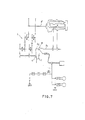
- In this proposal, as shown in Fig.7, a power turbine a which recovers the exhaust gas energy is provided in the exhaust gas passage b1, another passage c which by-passes the turbine a is provided being branched from b1 upstream of the turbine a, whereby defining a segment b2, and an exhaust gas passage switching means e is provided so as to close the upstream side passage b2 when the exhaust break is operating and a driving power is transmitted to the turbine a from the crankshaft d.
- Said exhaust gas passage switching means e is comprised of a rotary valve which has two internal ports with large and small diameters in a manner such that the passage b1 and another passage c are connected to each other by the port of small diameter when the exhaust break functions.
- Upon exhaust-breaking, by the exhaust passage switching means, the exhaust gas line b1 upstream of the by-pass line c is closed, and the upstream side b2 of the power turbine a is connected with the by-pass line c with the exhaust gas being throttled by the exhaust gass passage switching means e, so that the rotation of the crankshaft d is reversed by a gear train h and the rotative power is transmitted to the power turbine a, which is orginally intended to recover the energy. In this manner, the power turbine a will perform negative work against the crankshaft, i.e., pumping work, since the exhaust gas downstream of the power turbine a comes through the by-pass line c, as shown by dotted arrow in Fig. 7. Therefore, during exhaust-breaking, an engine break force of considerable magnitude, that is to say, a motor friction of the engine, a pumping work (negative work), and the exhasut break force, can be generated.
- However, the exhaust break may function, even when the engine is running above the rated revolution speed, i.e., when the engine is in overrun condition, for example, in a case of driving down a slope under a light load - high revolution speed condition. In this case, there is a great possibility that the power turbine may also come to an overrun condition, which should be avoided. The present inventors and others have found that the overrun is a factor to cause a significant deterioration of rotation performance of the rotating portion of the power turbine as well as the bearing portion, and come to the idea of this invention.
- One object of this invention is to provide a turbo compound engine whereby when a power turbine is driven to rotate by a crankshaft so as to transmit to the crankshaft a breaking force relative to the power turbine rotation, even at the rated speed of the engine, the power turbine wilt not reach an over rotative speed, so that a stable and relialbe breaking force is produced by the power turbine.
- Another object of this invention is to provide a turbo compound engine in which by preventing the power turbine from rotating beyond its over rotai- tive speed, a sudden breaking force will not be appllied to the crankshaft, and an unduly load will not added to the driving power transmissioin system, so that a durability and reliability of the driving force tramsmission system will be improved.
- A further object of this invention is to provide a turbo compound engine in which by rotating the power turbine below its over rotative speed, a certain rotation performance is maintained with the power turbine, and the rotative portion and the bearing portion which support the driving force transmission system.
- These objects are achieved by a turbo compound engine comprising an engine which has an exhaust gas passage and a crankshaft, a power turbine provided in the exhaust gas passage for recovering the exhaust gas energy, a driving power transmission means for drivingly connecting the crankshaft and the power turbine, a fluid passage connected to a portion of exhaust passage between the power turbine and the engine, and fluid passage switching means for closing the exhaust passage upstream of the fluid passage while opening the fluid passage during exhaust braking.
-
- Figure 1 is a system diagram, showing a preferred embodiment of the turbo compound engine of the present invention;
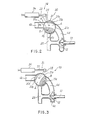
- Figures 2 and 3 are enlarged views of a portion of Fig.1, showing the switching positions of the rotary valve, the rotary valve having a first port of large diameter and a second port of small diameter and being disposed at the junction of the by-pass passage and the exhaust gas passage;
- Figure 4 is a diagram, showing the relationship between an engine brake force and the diameter of the small port;
- Figure 5 is a schematic cross sectional view, showing the directions of exhaust;
- Figure 6 depicts performance curves, showing the relationship between relative break force (revolution speed/engine output) and the revolution speed for a non-turbocharged engine and a highly supercharged engine;
- Figure 7 depicts a system diagram, showing a turbo compound engine of a related art.
- A preferred embodiment of the turbo compound engine according to the present invention will be described with reference to the accompanying drawings.
- In Fig.1, the
numeral 1 designates an engine, 2 the intake manifold, and 3 the exhaust manifold. To theexhasut manifold 3, there is connected anexhaust gas passage 4 consisting of 4a-4d, while the intake manifold 2 is connected to an intake air passage 5. - There is disposed the turbine 10a of the
turbocharger 10 at an intermediate point in exhaust passage 4a, while the compressor 10b of the tur-bocharge 10 is disposed an intermediate point in the intake passage 5. In the exhaust passge 4b downstream of theturbocharger 10, there is disposed apower turbine 12. - Repetitiously speaking, one object of this invention is to realize a turbo compound engine which is capable of securing an adequate engine break force relative to the engine output per- foemence. In this embodiment, in order to increase the engine break force, it is considered to be effective that a resistance force should be applied to the
rotative crankshaft 15 directly or indirectly, so that thecrankshaft 15 will be loaded with a considerable negative work. - As shown in Fig.1, a by-
pass line 25 is connected to theexhaust gas passage 4b between thepower turbine 12 and the turbine 10a of theturbo chager 10 at one end, and at the other end to the passage 4c downstream of thepower turbine 12. And at the junction of the by-pass line 25 upstream of thepower turbine 12, there is provided an exhaust gas passage switching means 30. - In this embodimetn, the fluid passage switching means 30 comprises, as shown in Figs. 1 to 3, a
rotary valve 31, which is disposed in the above mentioned junction and functions as an exhaust gas switching valve, and adriving mechanism 32 therefor. Therotary valve 31 comprises, as shown in Figs 2 and 3 , arotor 31 b, which is rotatably disposed in thecasing 31 a, a first port A, and a second port B with the two ports being formed whitin therotor 31 b in a manner such that the diameter of the first port A, d1, is equal to that of theexhasut passage 4b, d0, while the diameter of the second port B, d2, smaller than that of thepassage 25, d3. To thecasing 31 a, furthermore, twoopenings 31 are provided for theexhaust passage 4b, and thefluid passage 25, in a way that when the first port A is rotated into a position connecting theexhasut passage 4b, the second port B will be rotated away to disconnect theexhasut passage 4b and thefluid passage 25 as shwon in Fig.2. - The
driving mechanism 32 that drives and controls therotary valve 31 is constructed as follows. Namely, as shown in Figs.1 and 2, to therotor 31 b there is conncetd one end of alever member 35, while to the other free end thereof, namely that end which extends out of theexhasut passage 4b in the radial direction, there is connected the actuatingrod 33 of theactuator 34. - Now, referring to Fig.1, the
fluid chamber 37 of theactuator 34 is connected to afluid feeding apparatus 36 via afluid passage 39, and midway in thefluid passage 39, there is disposed anelectromagnetic valve 40 in a manner such that it connects thefluid chamber 37 and thefluid feeding apparatus 36 when acticated by electric current from aDC power sourc 45, such as a battery. It is to be noted that theelectromagnetic valve 40 is activated only when the neutrality sensing switch 41 that senses neutrality of theengine 1, the clutch action swith 42, and theexhaust brake swithc 43 are all turned ON. - The
numeral 47 denotes a switch for the reverse rotation electromagnetic clutch, which is, during normal operation, kept open. - Next, a gear train for connecting the
power turbine 12 and thecrankshaft 15 will be explained. - As shown in Fig.1, to the
output shaft 13a of theturbine shaft 13 of thepower turbine 12, there is integrally provided anoutput gear 16.Epicyclic gears 17a and 17b are engaged with theoutput gear 16. Theseepicyclic gears 17a and 17b are engaged with a ring gear 18 which rotates with aninput pump 21 a of thefluid coupling 21. - In clear terms, the
output gear 16 is connected to thefluid coupling 21 via theepicyclic gearing 19 which comprises theplanetary gears 17a and 17b as well as the ring or sun gear 18, so that the rotative force from thepower turbine 12 can be transmitted to theoutput pump 21 b of thefluid coupling 21. Theepicyclic gearing 19 is provided because it has a big moderating ratio and a high transmission efficiency. To theoutput pump 21 b. there is provided agear 20 which rotates with 21 b. - To the
crankshaft 15, there are provided thefirst crankshaft gear 23 which includes anelectromagnetic clutch 22 and whose rotation is stopped by the clutch 22, and thesecond crankshaft gear 24. Thesecond crankshaft gear 24 is engaged with thesecond intemidiate gear 27 which includes a one-way clutch 26. Thesecond intermidiate gear 27 is connected to saidoutupt gear 20 via afirst intermidiate gear 28 which has a mutual shaft with 27. - The
first intermidiate gear 28 andfirst crankshaft 23 are connected to each other by the reverseidle gear 29, and when the electromagnetic clutch 22 functions, that is to say, when the electromagneticclutch switch 47 is turned ON, thefirst crankshaft gear 23 and thefirst intermidiate gear 28 are connected, so that the rotative driving force from thecrankshaft 15 will be transmitted to thegear 20. At this time, thesecond intermidiate gear 27 andsecond crankshaft gear 24 are disconncetd to each other due to the one-way clutch 26, so that the rotative force will not transmitted with the only one-way clutch 26 rotating freely. - Meanwhile, the major object of this invention is to provide a turbo compound engine whereby an overrun of the
power turbine 12 will be avoided when the driving force from thecrankshaft 15 is transmitted to thepower turbine 12 at the rated revolution speed of the engine. Thus, the gear ratios offirst crankshaft gear 28, theidle gear 29, thefirst intermidiate gear 28, and thegear 20 must be determined in a manner such that when the engine runs at its rated revolution speed,power turbine 12 is prevented from overrunning. Specifically, the gear ratio between thegear 20 and thesecond crankshaft gear 24 is set to be larger than that betweenfirst crankshaft gear 23 and thegear 20. - In this particlular embodiment, the gear ratio between the
first crankshaft gear 23 and thefirst intermidiate gear 27 is smaller than that between thesecond crankshaft gear 24 and thesecond intermidiate gear 27. - The
gear train 56 which transmits the rotative power from thepower turbine 12 to thecrankshaft 15 comprises thesecond crankshaft gear 24, one-way clutch 26, and thefirst intermidiate gear 28, thegear 20, while theother gear train 57 which transmits the rotation power from thecrankshaft 15 to thepower turbine 12 comprises thefirst crankshaft gear 23, theidle gear 29, thefirst intermidiate gear 28, and thegear 20. - When the
power turbine 12 operates in normal mode and the breaking force is generated thereupon, i.e., in a case where thereverse gear train 57 is not provided with the engine, it goes without saying that the entire gear ratio of thegear train 56 should be set in a manner such that the power turbine will not reach its over rotative speed. - When the exhaust brake is operating, on the other hand, the neutrality sensing switch 41, the
clutch action sitch 42, and theexhaust brake switch 43 are all turned ON, whereby the switch for the reversing electromagnetic clutch 47 is turned ON, and theelectromagnetic switch 40 is turned ON, allowing thefluid feeding apparatus 36 to feed the working fluid into theaction chamber 37 of theactuator 34, which drives theaction rod 33 to act on therotary valve 31 via thelever member 35 so as to close theexhaust passage 4b, while connecting theexhaust passage 4d that lies downstream of therotary valve 31 and the by-pass line 25 via the second port B. - In this state, therefore, the
power turbine 12 is deprived of the rotation driving power of the exhasut gas, whereby the rotation power of thecrankshaft 15 is transmitted, in contrast to the case of normal rotation, to thegear 20 and thefluid coupling 21 via thefirst crankshaft gear 23, theidle gear 29, and thefirst intermidiate gear 28. Namely, thepower turbine 12 is now operating reversed, as shown in Fig. 5, as a compressor of poor efficiency, blowing air out of the exhaust passge 4c downstream thereto into the junction side of the by-pass line 25. Since the gas flowing toward thefluid passage 25 through the second port B is accelerated due to the throttling action of the second port B, a large amount of negative work in the form of the air stirring work and the air compressing work of thepower turbine 12 is forced against thecrankshaft 15. - Thus, when the exhasut brake is oprating, a large engine brake force is created on above mentioned negative work together with the negative work of the exhaust brake and the motor friction. The exhaust brake means includes an
exhuast manifold 3 and an exhaust brake valve (not shown) that is disposed in the exhaust passage 4a such that increase in the exhaust resistance brought about when this brake valve is fully closed, namely an increase in the pumping work, acts as the engine brake force. - It is to be noted here that the diameter of the second port B, d2, depends much on the form of the
power turbine 12, i.e., it is determined in a manner such that the overrun of thepower turbine 12 will not occur (see Figs 4 and 5). - In this embodiment, it is also permittable to provide a three-
way valve 55 in the exhaust gas passage 4c between thejunction 4e of the passage 4c and the by-pass line 25, and thepower turbine 12, thereby introducing the air from outside which may be clearer than the exhaust gas by closing the passage 4c when the exhaust break is operating. - In the above discribed embodiment, the
exhaust gas line 4 and the by-pass line 25 is opened/closed or switched by therotary valve 31 though, the rotary valve is not the only means. Namely, it is acceptable to provide and operate intercatively a shut-off valve which fully colses thepassage 4b upstream of the by-pass line 25 when the reverse rotative power is transmitted to thepower turbine 12 from thecrankshaft 15, and a throttle valve for controlling the geometric magnitude of the cross section of the by-pass line 25. And, it is also satisfactory that the by-pass line 25 may be alreadly throttled to a certain degree and then thepassage 4b may be opened/closed.
Claims (8)
- (1) A turbo compound engine comprising:an engine having an exhaust gas passage and a crankshaft;a power turbine disposed in said exhaust passage so as to recover the exhaust gas energy;driving power transmission means for drivingly connecting said power turbine and said crankshaft so as to transmit to said power turbine said driving power of a revolution speed below over rotative speed of said power turbine;a fluid passage connected to a portion of said exhaust passage which lies between said power turbine and said engine; anda fluid passage switching means for closing said exhaust passage upstream of said fluid passage while opening said fluid passage during exhaust braking.
- (2) The turbo compound engine according to claim 1, wherein said driving power transmission means includes gear train means for connecting said crankshaft and said power turbine, said gear train means including a plurality of gear trains with a gear ratio of each gear train being set to a value so as to prevent said power turbine from rotating over its over rotative speed.
- (3) The turbo compound engine according to claim 2, wherein said gear train means includes a plurality of gear trains and fluid clutches.
- (4) The turbo compound engine according to claim 1, wherein one end of said fluid passage is connected to the exhaust passage upstream of said power turbine, and the other end of said fluid passage is connected to the exhaust passage downstream of said power turbine.
- (5) The turbo compound engine according to claim 1. wherein said driving power transmission means includes reversing gear trains that transmit said driving power from said crankshaft to said power turbine when the exhaust brake is operating, and normal rotation gear trains that transmit said driving power from said power turbine to said crankshaft during normal operation, with the gear ratio of the former gear trains being smaller than that of the latter
- (6) The turbo compound engine according to claim 5, wherein said normal rotation gear trains and said reversing gear trains are respectively provided so as to transmit said driving power through fluid clutches and electromagnetic clutches.
- (7) The turbo compound engine according to claim 1, wherein said fluid passage switching means includes a switching valve that closes said exhaust passes upstream of said fluid passage while opens said fluid passage to a predetermined aperture when the exhaust brake is operating and the driving power is transmitted from said crankshaft to said power turbine, and also includes a driving mechanism for driving said switching valve.
- (8) The turbo compound engine according to claim 7, wherein said switching valve includes a rotary valve having a first port whose diameter is equal to that of said exhaust passage, as well as a second port whose diameter is smaller than that of said fluid passage, said switching valve being constructed so as to be activated by said driving mechanism in order to connect said second port to said fluid passage, thereby disconnecting said first port from said exhaust passage when the exhaust brake operates and the driving power is being transmitted from said crankshaft to said power turbine.
Applications Claiming Priority (2)
| Application Number | Priority Date | Filing Date | Title |
|---|---|---|---|
| JP61308776A JPS63162936A (en) | 1986-12-26 | 1986-12-26 | Turbo compound engine |
| JP308776/86 | 1986-12-26 |
Publications (3)
| Publication Number | Publication Date |
|---|---|
| EP0272680A2 true EP0272680A2 (en) | 1988-06-29 |
| EP0272680A3 EP0272680A3 (en) | 1988-11-30 |
| EP0272680B1 EP0272680B1 (en) | 1992-06-03 |
Family
ID=17985165
Family Applications (1)
| Application Number | Title | Priority Date | Filing Date |
|---|---|---|---|
| EP87118996A Expired - Lifetime EP0272680B1 (en) | 1986-12-26 | 1987-12-22 | Turbo compound engine |
Country Status (4)
| Country | Link |
|---|---|
| US (1) | US4800726A (en) |
| EP (1) | EP0272680B1 (en) |
| JP (1) | JPS63162936A (en) |
| DE (1) | DE3779591T2 (en) |
Cited By (9)
| Publication number | Priority date | Publication date | Assignee | Title |
|---|---|---|---|---|
| EP0301547B1 (en) * | 1987-07-30 | 1992-10-14 | Isuzu Motors Limited | Turbo compound engine |
| EP0477579A3 (en) * | 1990-09-25 | 1993-08-11 | Cummins Engine Company, Inc. | Power turbine bypass for improved compression braking |
| US5884482A (en) * | 1994-05-13 | 1999-03-23 | Scania Cv Aktiebolag | Combustion engine of turbocompound type with exhaust gas brake |
| WO2005068801A1 (en) * | 2004-01-15 | 2005-07-28 | Voith Turbo Gmbh & Co. Kg | Turbine compound system |
| CN103397934A (en) * | 2013-07-04 | 2013-11-20 | 广西玉柴机器股份有限公司 | Internal combustion engine waste gas reuse device |
| CN104314695A (en) * | 2014-09-30 | 2015-01-28 | 东风商用车有限公司 | Variable-speed-ratio compound turbine system and application method thereof |
| EP2942500A1 (en) * | 2014-05-07 | 2015-11-11 | Benteler Automobiltechnik GmbH | Exhaust gas heat exchanger with bypass tube |
| EP2978950A1 (en) * | 2013-05-10 | 2016-02-03 | Achates Power, Inc. | Air handling constructions with turbo-compounding for opposed-piston engines |
| US10850860B1 (en) | 2019-09-09 | 2020-12-01 | Hamiliton Sunstrand Corporation | Internal combustion engines with unidirectional compounding drives |
Families Citing this family (16)
| Publication number | Priority date | Publication date | Assignee | Title |
|---|---|---|---|---|
| DE3866018D1 (en) * | 1987-05-22 | 1991-12-12 | Isuzu Motors Ltd | ENGINE BRAKE SYSTEM. |
| JPS63302137A (en) * | 1987-05-30 | 1988-12-09 | Isuzu Motors Ltd | Turbocompound engine |
| JPH0639901B2 (en) * | 1987-10-28 | 1994-05-25 | いすゞ自動車株式会社 | Turbo compound engine |
| US4897998A (en) * | 1987-10-28 | 1990-02-06 | Isuzu Motors Limited | Turbo compound engine |
| JPH01116234A (en) * | 1987-10-28 | 1989-05-09 | Isuzu Motors Ltd | Turbo compound engine |
| JPH09190U (en) * | 1996-10-28 | 1997-04-08 | 廣瀬商事株式会社 | Injection molding equipment for patterned dishes |
| DE10290840B4 (en) * | 2001-03-01 | 2007-07-26 | Voith Turbo Gmbh & Co. Kg | Drive unit with an internal combustion engine and an exhaust gas turbocharger |
| SE523149C2 (en) * | 2001-08-20 | 2004-03-30 | Volvo Lastvagnar Ab | Turbo engine type combustion engine device |
| US20050087171A1 (en) * | 2002-10-02 | 2005-04-28 | Cory Lown | Low restriction engine brake and methods |
| DE10360155A1 (en) * | 2003-12-20 | 2005-07-21 | Voith Turbo Gmbh & Co. Kg | Powertrain with exhaust use and control method |
| US8001783B2 (en) * | 2008-01-24 | 2011-08-23 | Cummins Ip, Inc. | Apparatus, system, and method for turbocharger bypass and exhaust braking with a single valve |
| US8069664B2 (en) * | 2008-09-18 | 2011-12-06 | GM Global Technology Operations LLC | Integrated inlet and bypass throttle for positive-displacement supercharged engines |
| US8127544B2 (en) * | 2010-11-03 | 2012-03-06 | Paul Albert Schwiesow | Two-stroke HCCI compound free-piston/gas-turbine engine |
| US9108628B2 (en) * | 2012-08-31 | 2015-08-18 | GM Global Technology Operations LLC | Turbo compounding hybrid generator powertrain |
| US10240521B2 (en) | 2015-08-07 | 2019-03-26 | Pratt & Whitney Canada Corp. | Auxiliary power unit with variable speed ratio |
| US20180058311A1 (en) * | 2016-08-25 | 2018-03-01 | Hyundai Motor Company | Turbo compound system for vehicle and method of controlling the same |
Family Cites Families (5)
| Publication number | Priority date | Publication date | Assignee | Title |
|---|---|---|---|---|
| US2375852A (en) * | 1941-05-17 | 1945-05-15 | Sulzer Ag | Reversible supercharged twostroke internal-combustion engine |
| DE962764C (en) * | 1954-09-10 | 1957-04-25 | Maschf Augsburg Nuernberg Ag | Internal combustion engine with exhaust gas turbocharging |
| US4224794A (en) * | 1978-12-28 | 1980-09-30 | Cummins Engine Company, Inc. | Turbine assembly |
| CH637707A5 (en) * | 1979-06-13 | 1983-08-15 | Rueti Ag Maschf | WEB SHEET FOR A NOZZLE WEAVING MACHINE. |
| JPS61921A (en) * | 1984-06-12 | 1986-01-06 | Hitachi Maxell Ltd | Magnetic recording medium |
-
1986
- 1986-12-26 JP JP61308776A patent/JPS63162936A/en active Granted
-
1987
- 1987-12-22 DE DE8787118996T patent/DE3779591T2/en not_active Expired - Fee Related
- 1987-12-22 US US07/136,319 patent/US4800726A/en not_active Expired - Fee Related
- 1987-12-22 EP EP87118996A patent/EP0272680B1/en not_active Expired - Lifetime
Cited By (16)
| Publication number | Priority date | Publication date | Assignee | Title |
|---|---|---|---|---|
| EP0301547B1 (en) * | 1987-07-30 | 1992-10-14 | Isuzu Motors Limited | Turbo compound engine |
| EP0477579A3 (en) * | 1990-09-25 | 1993-08-11 | Cummins Engine Company, Inc. | Power turbine bypass for improved compression braking |
| US5884482A (en) * | 1994-05-13 | 1999-03-23 | Scania Cv Aktiebolag | Combustion engine of turbocompound type with exhaust gas brake |
| WO2005068801A1 (en) * | 2004-01-15 | 2005-07-28 | Voith Turbo Gmbh & Co. Kg | Turbine compound system |
| CN100447386C (en) * | 2004-01-15 | 2008-12-31 | 福伊特涡轮机两合公司 | Turbo compound system |
| RU2354834C2 (en) * | 2004-01-15 | 2009-05-10 | Фойт Турбо ГмбХ унд Ко.КГ | Turbo-compound system |
| US7694519B2 (en) | 2004-01-15 | 2010-04-13 | Voith Turbo Gmbh & Co. Kg | Turbine compound system |
| EP2978950A1 (en) * | 2013-05-10 | 2016-02-03 | Achates Power, Inc. | Air handling constructions with turbo-compounding for opposed-piston engines |
| WO2015000253A1 (en) * | 2013-07-04 | 2015-01-08 | 广西玉柴机器股份有限公司 | Internal combustion engine exhaust gas recycling device |
| CN103397934A (en) * | 2013-07-04 | 2013-11-20 | 广西玉柴机器股份有限公司 | Internal combustion engine waste gas reuse device |
| EP2942500A1 (en) * | 2014-05-07 | 2015-11-11 | Benteler Automobiltechnik GmbH | Exhaust gas heat exchanger with bypass tube |
| US9964075B2 (en) | 2014-05-07 | 2018-05-08 | Benteler Automobiltechnik Gmbh | Exhaust-gas heat exchanger with bypass pipe |
| CN104314695A (en) * | 2014-09-30 | 2015-01-28 | 东风商用车有限公司 | Variable-speed-ratio compound turbine system and application method thereof |
| CN104314695B (en) * | 2014-09-30 | 2016-09-21 | 东风商用车有限公司 | Variable-speed-ratio compound turbine system and application method thereof |
| US10850860B1 (en) | 2019-09-09 | 2020-12-01 | Hamiliton Sunstrand Corporation | Internal combustion engines with unidirectional compounding drives |
| EP3789594A1 (en) * | 2019-09-09 | 2021-03-10 | Hamilton Sundstrand Corporation | Internal combustion engines with unidirectional compounding drives |
Also Published As
| Publication number | Publication date |
|---|---|
| JPH0568617B2 (en) | 1993-09-29 |
| DE3779591D1 (en) | 1992-07-09 |
| JPS63162936A (en) | 1988-07-06 |
| DE3779591T2 (en) | 1993-01-21 |
| EP0272680B1 (en) | 1992-06-03 |
| US4800726A (en) | 1989-01-31 |
| EP0272680A3 (en) | 1988-11-30 |
Similar Documents
| Publication | Publication Date | Title |
|---|---|---|
| US4800726A (en) | Turbo compound engine | |
| US4748812A (en) | Turbo compound engine | |
| EP0301547B1 (en) | Turbo compound engine | |
| US4145888A (en) | Combined turbocharger and accessory drive | |
| US4858440A (en) | Turbo-compound engine | |
| JPH01116234A (en) | Turbo compound engine | |
| US20020096156A1 (en) | Multi-speed gear arrangement for a centrifugal engine charger | |
| JPS6349053B2 (en) | ||
| JP3137802B2 (en) | Engine supercharger | |
| CN114961982A (en) | Integrated mechanical supercharger and turbocharger | |
| WO1992002719A1 (en) | Two and four stroke compound diesel engines with cvt drive | |
| JPS6240096Y2 (en) | ||
| JPH05180089A (en) | Exhaust gas recirculating device for supercharge engine | |
| GB2395231A (en) | Turbocharger with an attached electric motor | |
| JP3137801B2 (en) | Engine supercharger | |
| JPS6219572B2 (en) | ||
| JPH0458005A (en) | Scavenging device for diesel engine | |
| JPS63111239A (en) | Turbo compound engine | |
| JPH041308Y2 (en) | ||
| SU1229395A1 (en) | Combined power plant | |
| JP2534559Y2 (en) | Gear device for driving supercharger in turbo compound engine | |
| JPH09268921A (en) | Engine with turbocharger | |
| JPS60240831A (en) | Power turbine power transmission mechanism and turbo-compound system | |
| JPH053717Y2 (en) | ||
| JP2778866B2 (en) | In-vehicle turbo compound engine |
Legal Events
| Date | Code | Title | Description |
|---|---|---|---|
| PUAI | Public reference made under article 153(3) epc to a published international application that has entered the european phase |
Free format text: ORIGINAL CODE: 0009012 |
|
| AK | Designated contracting states |
Kind code of ref document: A2 Designated state(s): DE GB |
|
| PUAL | Search report despatched |
Free format text: ORIGINAL CODE: 0009013 |
|
| AK | Designated contracting states |
Kind code of ref document: A3 Designated state(s): DE GB |
|
| 17P | Request for examination filed |
Effective date: 19890331 |
|
| 17Q | First examination report despatched |
Effective date: 19890712 |
|
| GRAA | (expected) grant |
Free format text: ORIGINAL CODE: 0009210 |
|
| AK | Designated contracting states |
Kind code of ref document: B1 Designated state(s): DE GB |
|
| REF | Corresponds to: |
Ref document number: 3779591 Country of ref document: DE Date of ref document: 19920709 |
|
| PLBE | No opposition filed within time limit |
Free format text: ORIGINAL CODE: 0009261 |
|
| STAA | Information on the status of an ep patent application or granted ep patent |
Free format text: STATUS: NO OPPOSITION FILED WITHIN TIME LIMIT |
|
| 26N | No opposition filed | ||
| PGFP | Annual fee paid to national office [announced via postgrant information from national office to epo] |
Ref country code: GB Payment date: 19951201 Year of fee payment: 9 |
|
| PGFP | Annual fee paid to national office [announced via postgrant information from national office to epo] |
Ref country code: DE Payment date: 19960227 Year of fee payment: 9 |
|
| PG25 | Lapsed in a contracting state [announced via postgrant information from national office to epo] |
Ref country code: GB Effective date: 19961222 |
|
| GBPC | Gb: european patent ceased through non-payment of renewal fee |
Effective date: 19961222 |
|
| PG25 | Lapsed in a contracting state [announced via postgrant information from national office to epo] |
Ref country code: DE Effective date: 19970902 |