EP0272326B1 - Locking construction of timepiece - Google Patents
Locking construction of timepiece Download PDFInfo
- Publication number
- EP0272326B1 EP0272326B1 EP87902747A EP87902747A EP0272326B1 EP 0272326 B1 EP0272326 B1 EP 0272326B1 EP 87902747 A EP87902747 A EP 87902747A EP 87902747 A EP87902747 A EP 87902747A EP 0272326 B1 EP0272326 B1 EP 0272326B1
- Authority
- EP
- European Patent Office
- Prior art keywords
- coil
- timepiece
- securing
- plate
- stator
- Prior art date
- Legal status (The legal status is an assumption and is not a legal conclusion. Google has not performed a legal analysis and makes no representation as to the accuracy of the status listed.)
- Expired
Links
- 238000010276 construction Methods 0.000 title claims abstract description 22
- 239000000470 constituent Substances 0.000 abstract 2
- 239000000758 substrate Substances 0.000 description 17
- 239000000463 material Substances 0.000 description 12
- 229920003023 plastic Polymers 0.000 description 11
- 239000004033 plastic Substances 0.000 description 11
- 239000010453 quartz Substances 0.000 description 7
- VYPSYNLAJGMNEJ-UHFFFAOYSA-N silicon dioxide Inorganic materials O=[Si]=O VYPSYNLAJGMNEJ-UHFFFAOYSA-N 0.000 description 7
- RYGMFSIKBFXOCR-UHFFFAOYSA-N Copper Chemical compound [Cu] RYGMFSIKBFXOCR-UHFFFAOYSA-N 0.000 description 5
- 239000011889 copper foil Substances 0.000 description 5
- 238000000034 method Methods 0.000 description 3
- 239000004020 conductor Substances 0.000 description 2
- 239000000853 adhesive Substances 0.000 description 1
- 230000001070 adhesive effect Effects 0.000 description 1
- 230000000694 effects Effects 0.000 description 1
- 229920006351 engineering plastic Polymers 0.000 description 1
- 230000001788 irregular Effects 0.000 description 1
- 230000002093 peripheral effect Effects 0.000 description 1
Images




Classifications
-
- G—PHYSICS
- G04—HOROLOGY
- G04C—ELECTROMECHANICAL CLOCKS OR WATCHES
- G04C3/00—Electromechanical clocks or watches independent of other time-pieces and in which the movement is maintained by electric means
- G04C3/008—Mounting, assembling of components
Definitions
- the present invention relates to a securing construction for timepieces. Although the present invention is not so restricted, it relates more particularly to a securing construction for analogue electronic timepieces provided with frames, gear trains, motors, circuit members and the like.
- Figure 1 shows a construction for securing stators and coil blocks in a prior electronic timepiece.
- Guide screw pins 16 and 16′ are driven into openings in a plate 11 so as to be secured therein by interference.
- a stator 12 and a coil block 13 are positioned by the guide pins 16 and 16′ and are secured to a plate 11 by tightening screws 17 and 17′.
- the plastics material can easily be modified until the stress becomes zero in the course of time. In particular, the plastics material is modified easier under high temperature). Consequently, spaces are generated between the core of the coil block and the stator, and the properties of the construction are inferior due to the reduction of the magnetic connection.
- a securing construction for a timepiece comprising a magnetic core provided with a coil; a stator contacting said magnetic core; a coil lead member which is electrically connected to the coil; a circuit member which contacts the coil lead member; a plate which supports the magnetic core, the stator, the coil lead member, and the circuit member; and securing means which engages the plate, the securing means securing the magnetic core, the stator, the coil lead member and the circuit member to the plate.
- securing means a screw is used.
- the object of the present invention is therefore to provide a securing construction for a timepiece which does not use any screws, to decrease the number of parts, and to provide a low cost timepiece having high quality and reliability.
- a securing construction for a timepiece comprising a magnetic core provided with a coil; a stator contacting said magnetic core; a coil lead member which is electrically connected to the coil; a circuit member which contacts the coil lead member; a plate which supports the magnetic core, the stator, the coil lead member, and the circuit member; and securing means which engages the plate, the securing means securing the magnetic core, the stator, the coil lead member and the circuit member to the plate, characterised in that the securing means has at least one resilient portion which is or are solely responsible for effecting the said securing, whereby the at least one resilient portion resiliently urges the coil lead member and circuit member into electrical contact with each other, and at the same time resiliently urges the magnetic core and stator into magnetic contact with each other.
- the securing means is a battery positive terminal.
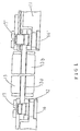
- Figure 2 is a plan view of a first embodiment of an assembly, or securing construction, for use in a timepiece according to the present invention.
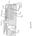
- Figures 3, 4 and 5 are sectional views of parts of the construction of Figure 2.
- the reference numeral 101 is a frame of a timepiece, that is, a plate made of plastics material, which is provided to guide and support the gear trains, motors, circuit members and the like described below.
- the plate 101 has projecting portions 101-a, 101-b, 101-c, and 101-d at the periphery thereof. The projecting portions are provided for engagement with a supporting member 119, that is, a positive terminal of a battery described below.
- the reference numerals 102, 103, 104, 105, 106, 107 and 108 are a centre wheel and pinion, a third wheel and pinion, a fourth wheel and pinion, a fifth wheel and pinion, a rotor, a clutch wheel and a minute wheel, respectively.
- the reference numeral 109 is a clutch plate and is provided as a mounting for the lower pivot-pin of the third wheel in the plate 101.
- the reference numeral 110 is a stator and the reference numeral 111 is a negative terminal of a battery 111a.
- the reference numeral 112 is a bridge member, made of plastics material, which is provided to guide and support the above mentioned respective members.
- the reference numeral 113 is a coil block, i.e.
- a magnetic core having a coil 117a which is provided to convert electric signals applied thereto from a circuit block described below into magnetic energy.
- the coil block 113 is brought in contact with a stator, so that the rotor described above is rotated.
- the reference numeral 114 is the said circuit block.
- a MOS-IC chip 115 and a quartz oscillator 116 are mounted on the circuit block 114.
- the circuit block 114 is electrically connected to the negative terminal of the battery upon the contact of the negative terminal of the battery described above with the circuit block. Further electric signals are transmitted upon the contact of a coil lead substrate 117, which is electrically connected to the coil 117a, with the circuit block 114.
- the reference numeral 118 is a stem which serves as external operating member. All of the above-mentioned members are guided and supported by the plate or the bridge member, but have no securing means.
- the reference numeral 119 is the battery positive terminal which is provided to secure and support all of the above mentioned members and has the functions described below.
- the battery positive terminal 119 has portions 119-a, 119-b, 119-c and 119-d engaging with the projecting portions of the plate 101, which serves as a securing means of the said members.
- the reference numerals 119-e, 119-f and 119-g indicate resilient portions, respectively of the terminal 119.
- the reference numeral 119-e ( Figure 5), is an output terminal portion of the stator 110 and of the coil block 113.
- the reference numeral 119-f ( Figure 4) is an output terminal portion of the stator 110 and of the coil block 113, and of the coil lead substrate 117 and the circuit pattern.
- the reference numeral is a resilient portion 119-g ( Figure 3) which is provided to press against a case 116 of a quartz oscillator.
- the reference numeral 119-h ( Figure 2) is an electrically contacting resilient portion which is in contact with the side of the battery 111a.
- the reference numeral 119-i ( Figure 2) is a positive conductive resilient portion which is provided to conduct the positive potential to the circuit block 114 with a uniform contact pressure, because the positive conductive resilient portion is in contact with the above-mentioned circuit block pattern.
- the battery positive terminal 119 is fixed in position by being mounted on shaft portions 101-e, 101-f and 101-g of the plate 101.
- the engagement portions 119-a and 119-d between the battery positive terminal 119-g and the projecting portion 101-b of the plate 101 are assembled over the slanting surface 101-h of the projecting portion 101-b.
- the timepiece members supported by the plate 101 and the battery positive terminal 119, the engagement portion 119-b of the battery positive terminal, and the variation in the height of the terminal 119 are absorbed by the resilient member 119-b positioned near the portion 101-b.
- the engaging portion of the battery positive terminal is pushed down excessively by an assembling means like a jig or the like and is assembled in the direction of the arrow B of Figure 3, so that the engagement portion 119-b of the battery positive terminal is engaged with the projecting portion 101-b of the plate 101.
- the engagement portion 119-b extends over the slanting surface 101-h and after passing the slanting portion 101-h, the engagement portion 119-b is assembled in the engaged position by the spring power itself of the battery positive terminal 119.
- the engagement portions 101 and 101-d may be engaged with the projecting portion of the plate formed in a known T-shape or hole type.
- the head portions of the plate guide shafts 101-e, 101-f and 101-g are produced by deformation under heat. Further, the guide shafts 101-e, 101-f and 101-g and the projecting portions of the plate 101 receive the reaction of the battery positive terminal.
- Such a securing construction utilizing a battery positive terminal does not require screws or screw pins and further, since the resilient metallic portions are in contact with each other, the contact pressure is kept uniform irrespective of the length of time, so that there is a high degree of reliability.
- the resilient portion of the battery positive terminal is provided near a portion meshing with a projecting portion of the plate, the resilient portion exerts a contact load. That is, the closer the contact portions of the stator and the coil block are positioned to the engaging portion of the timepiece, the better they can be operated.
- the engaged portion of the plate has a projecting shape, but there is no problem in function even if the engaged portion has a projecting portion and the engaging portion has a projecting portion.
- Figure 6 is a plan view
- Figures 7 and 8 are sectional views of parts of Figure 6.
- the reference numeral 201 represents a plate, that is a frame of an analogue timepiece which is made of plastics material and is provided to mount and support trains, a motor, circuit members and so on (described below). Projecting portions 201-a, 201-b, 201-c, and 201-d are provided at peripheral portions of the plate 201 to be engaged with a battery positive terminal 218 serving as a supporting member (as described below).
- the reference numerals 202, 203, 204, 205, 206, 207, 208 are a centre wheel and pinion, a third wheel and pinion, a fourth wheel and pinion, a fifth wheel and pinion, a rotor, a clutch wheel and a minute wheel, respectively.
- the reference numeral 209 is a stator and the reference numeral 210 is a battery negative terminal.
- the reference numeral 211 represents a bridge member which is provided to mount and support the above-mentioned members.
- the reference numeral 212 is a coil block, i.e. a magnetic core having a coil 212-a.
- the coil block 212 is provided to convert the electric signal applied thereto from a circuit block described below to magnetic energy and to rotate the above-mentioned rotor 206, upon the contact of the coil block 212 with the stator 209.
- the reference numeral 213 is a circuit block on which a MOS-IC chip 214 and a quartz oscillator 215 are mounted. Upon the contact of the circuit block 14 with the battery negative terminal, they are electrically connected to each other. Further, upon the contact of a coil lead substrate 216, which is electrically connected to the coil 212-a of the coil block 212, with the circuit block 114, electrical signals are transmitted therebetween.
- the reference numeral 217 is a stem which serves as an external operating member.
- the reference numeral 218 is a battery positive terminal which is provided to secure and press together all the above members and has the functions described below.
- the battery positive terminal 218 has portions 218-a, 218-b, 218-c and 218-d engaging with the projecting portion of the plate 201 and serves as means for securing the said members.
- the terminal 219 is mounted on guide shafts 201-e, 201-f and 201-g which are secured thereto by heat deformation.
- the reference numerals 218-e and 218-f are spring portions of the battery positive terminal 218 which are substantially symmetrical and have equal spring constants.
- the centre portion of the terminal 218 is supported by a spring beam portion 218-g.
- Figure 7 shows a sectional view of the spring portion in detail.
- Spring portions 218-e and 218-f are constructed so as to electrically connect patterns 213-a, 213-b of circuit substrate 213 with patterns 216-a, 216-b of a coil lead substrate 216, as a result of the pressure exerted by the spring portions 218-e and 218-f. Further, the spring portions 218-e, 218-f also serve to magnetically connect the coil block 212 with the stator 209 so as to form a motor as a result of the said pressure.
- the spring portions 218-e and 218-f are supported by the resilient beam portion 218-g at the centre portion thereof.
- the beam can be twisted, so that both spring portions 218-e, 218-f are slidably movable. Even if the contact pressure of the output conductive terminals of the coil is not uniform because of the irregular height of the heat deformed portions or the irregularity of the respective members, the curvature of the plate and so on, both spring portions enable equal pressure to be applied to the respective patterns. Further, it is possible to stabilize the pressure force at the magnetic contact between the coil block 212 and the stator 209 of the motor.
- the quartz oscillator 215 of the timepiece is secured in the same way.
- the spring portions 218-h and 218-i have a symmetrical shape and equal spring constants. The centre portion of them is supported by both end supporting beams 218-j and 218-k. As shown in Figure 8, the quartz oscillator 215 is disposed obliquely in view of the construction of the circuit substrate 213. In the same way as that of the above-mentioned output conductive portions of the coil, both springs 218-h and 218-i are supported at the centre portion thereof.
- the quartz oscillator 215 is disposed obliquely, it is supported under a substantially uniform pressure by both springs 218-f and 218-i due to the function of resilient supporting beams 218-j and 218-k which are moved torsionally and slidably, whereby it is possible to secure the quartz oscillator 215 securely.
- a battery positive terminal is utilized as a securing member, but even if another securing member is utilized, the same effects can be obtained.
- FIG. 9 shows a sectional view of a third embodiment according to the present invention.
- a plate 301 is made of engineering plastics material and is formed integrally with dowels 301a, 301a′, and with a projection 301b.
- a guide pin 306 is secured to the plate 301.
- a stator 302 is mounted on the plate 301 and positioned by the dowels 301a and 301a′.
- a magnetic core 303a is also positioned by the dowels 301a and 301a′ and is mounted on the stator 302.
- a coil lead substrate 303c is fixed at one side of the magnetic core 303a.
- a coil 303b is wound around the magnetic core 303a with an insulating member 303e therebetween. Both ends of the coil 303b are in adhesive contact with respective copper foil portions 303c′ on the coil lead substrate 303c.
- a coil frame 303d is secured to the magnetic core 303a.
- the coil block 303 comprises the magnetic core 303a, the coil 303b, the coil lead substrate 303c, the coil frame 303d and the insulating member 303e.
- a circuit substrate 305 is mounted on the coil lead substrate 303-c.
- the respective copper foils 303c′ on the coil lead substrate 303c are in contact with a copper foil 305a which is connected to the output terminal of an MOS-IC (not shown) mounted on the circuit substrate 305.
- the copper foil portion 303c′ of the coil lead substrate 303c is electrically connected to the copper foil portion 305a of the circuit substrate 305 by the spring force of the motor supporting spring 304′, whereby the stator 302 and the magnetic core 303a are pressed together.
- the stator 302 and the magnetic core 303a are pressed down by the motor supporting spring 304′.
- a magnetic supporting spring 304 is secured together with a bridge member 308 by a member 306 for securing the bridge member 308 and by a fixing screw 307.
- the motor supporting spring 304′ is secured by engaging with the projection 301b extending from a side of the plate 301.
- the motor supporting spring 304 is secured by the screw 307 and the motor supporting spring 304' is secured by engaging with the projection 301b.
- other securing methods may be utilized. For example, both of them may be secured by screws, or may be secured by the engaging with the projection, or may be secured by the same screws.
Landscapes
- Physics & Mathematics (AREA)
- General Physics & Mathematics (AREA)
- Electromechanical Clocks (AREA)
Abstract
Description
- The present invention relates to a securing construction for timepieces. Although the present invention is not so restricted, it relates more particularly to a securing construction for analogue electronic timepieces provided with frames, gear trains, motors, circuit members and the like.
- It is known from the prior art that parts of analogue timepieces are secured together by screws.
- Figure 1 shows a construction for securing stators and coil blocks in a prior electronic timepiece.
Guide screw pins stator 12 and acoil block 13 are positioned by theguide pins screws - Further, as a construction for securing parts of timepieces without utilizing screws, it is also known to employ heat to deform one of the parts after assembly.
- However, such a prior securing construction utilizing screws has the following problems:
- (1)
- Screws and screw pins are required, so that costs are increased according to the increase in numbers of the parts concerned.
- (2)
- The control of torque is not stabilized when screws are tightened in assembly. Therefore, such a construction has the disadvantage that when the torque applied is small, the screws may become loose, and when the torque applied is large, the screws may be broken off.
- (3)
- When a frame of a timepiece is made of a low strength material such as plastics material, such a construction has disadvantages in quality and in respect of after-sale services. This is because the frames of the timepieces may be broken by the driving in of the screw pins, or the frame of the timepiece may be broken or the fixing power of the screw pins may be reduced in the course of time because some stress is always added to the frame due to the interference between the screw pins and the frame.
- With respect to the method for securing members by utilizing heat deformation, the following problems occur in the magnetic contacting parts of a core of a coil block and a stator, and in an electroconductive portion.
- (1) When a core of the coil block and the stator are in magnetic contact with each other by means of heat deformation, sufficient heat deformation of a part is required in order to obtain both sufficient contact and sufficient contact load between them. When the heat deformation is effected by utilizing some jigs, it is difficult to ensure that there is sufficient contact and contact load in view of the dimensional variation of the respective members. As a result, an additional process for effecting heat deformation is required.
- Further, in heat deformation, it is difficult to produce the contact load between the coil block and the stator. (As a reaction is always imparted to the plastics material, the plastics material can easily be modified until the stress becomes zero in the course of time. In particular, the plastics material is modified easier under high temperature). Consequently, spaces are generated between the core of the coil block and the stator, and the properties of the construction are inferior due to the reduction of the magnetic connection.
- (2) With regard to an electrical conductor, the same thing occurs as mentioned above. Namely, it is always necessary to press the electric conductors toward each other under a contact load of at least 50 g. However, as mentioned above, as stress is always imparted to the plastics material, the heat deformed portion is modified in the course of time and there is danger that there will be imperfect conduction.
- (3) When the coil block is brought into contact with the stator solely by heat deformation, it is not possible to provide any after-sale service at all, and the product may become worthless.
- In US-A-4,555,184 there is disclosed a securing construction for a timepiece comprising a magnetic core provided with a coil; a stator contacting said magnetic core; a coil lead member which is electrically connected to the coil; a circuit member which contacts the coil lead member; a plate which supports the magnetic core, the stator, the coil lead member, and the circuit member; and securing means which engages the plate, the securing means securing the magnetic core, the stator, the coil lead member and the circuit member to the plate. As securing means a screw is used.
- The object of the present invention is therefore to provide a securing construction for a timepiece which does not use any screws, to decrease the number of parts, and to provide a low cost timepiece having high quality and reliability.
- According to the present invention, there is therefore provided a securing construction for a timepiece comprising a magnetic core provided with a coil; a stator contacting said magnetic core; a coil lead member which is electrically connected to the coil; a circuit member which contacts the coil lead member; a plate which supports the magnetic core, the stator, the coil lead member, and the circuit member; and securing means which engages the plate, the securing means securing the magnetic core, the stator, the coil lead member and the circuit member to the plate, characterised in that the securing means has at least one resilient portion which is or are solely responsible for effecting the said securing, whereby the at least one resilient portion resiliently urges the coil lead member and circuit member into electrical contact with each other, and at the same time resiliently urges the magnetic core and stator into magnetic contact with each other.
- Preferably the securing means is a battery positive terminal.
- Preferably there are a plurality of symmetrically arranged resilient portions.
- The invention is illustrated, merely by way of example in the accompanying drawings, in which:
- Figure 1 is a sectional view which shows an assembly for use in a prior timepiece;
- Figure 2 is a plan view of an assembly for use in a timepiece in accordance with the present invention;
- Figures 3, 4 and 5 are sectional views of parts of the assembly of Figure 2;
- Figure 6 is a plan view of a second embodiment of an assembly for use in a timepiece in accordance with the present invention;
- Figures 7 and 8 are sectional views of parts of the assembly of Figure 6; and
- Figure 9 is a sectional view of a third embodiment of an assembly for use in a timepiece in accordance with the present invention.
- The present invention is explained in more detail with reference to the accompanying drawings.
- Figure 2 is a plan view of a first embodiment of an assembly, or securing construction, for use in a timepiece according to the present invention. Figures 3, 4 and 5 are sectional views of parts of the construction of Figure 2. The
reference numeral 101 is a frame of a timepiece, that is, a plate made of plastics material, which is provided to guide and support the gear trains, motors, circuit members and the like described below. Theplate 101 has projecting portions 101-a, 101-b, 101-c, and 101-d at the periphery thereof. The projecting portions are provided for engagement with a supportingmember 119, that is, a positive terminal of a battery described below. Thereference numerals reference numeral 109 is a clutch plate and is provided as a mounting for the lower pivot-pin of the third wheel in theplate 101. Thereference numeral 110 is a stator and the reference numeral 111 is a negative terminal of a battery 111a. Thereference numeral 112 is a bridge member, made of plastics material, which is provided to guide and support the above mentioned respective members. Thereference numeral 113 is a coil block, i.e. a magnetic core having acoil 117a, which is provided to convert electric signals applied thereto from a circuit block described below into magnetic energy. Thecoil block 113 is brought in contact with a stator, so that the rotor described above is rotated. Thereference numeral 114 is the said circuit block. A MOS-IC chip 115 and aquartz oscillator 116 are mounted on thecircuit block 114. Thecircuit block 114 is electrically connected to the negative terminal of the battery upon the contact of the negative terminal of the battery described above with the circuit block. Further electric signals are transmitted upon the contact of acoil lead substrate 117, which is electrically connected to thecoil 117a, with thecircuit block 114. Thereference numeral 118 is a stem which serves as external operating member. All of the above-mentioned members are guided and supported by the plate or the bridge member, but have no securing means. - The
reference numeral 119 is the battery positive terminal which is provided to secure and support all of the above mentioned members and has the functions described below. - First, the battery
positive terminal 119 has portions 119-a, 119-b, 119-c and 119-d engaging with the projecting portions of theplate 101, which serves as a securing means of the said members. - The reference numerals 119-e, 119-f and 119-g indicate resilient portions, respectively of the
terminal 119. The reference numeral 119-e (Figure 5), is an output terminal portion of thestator 110 and of thecoil block 113. The reference numeral 119-f (Figure 4) is an output terminal portion of thestator 110 and of thecoil block 113, and of thecoil lead substrate 117 and the circuit pattern. The reference numeral is a resilient portion 119-g (Figure 3) which is provided to press against acase 116 of a quartz oscillator. The reference numeral 119-h (Figure 2) is an electrically contacting resilient portion which is in contact with the side of the battery 111a. The reference numeral 119-i (Figure 2) is a positive conductive resilient portion which is provided to conduct the positive potential to thecircuit block 114 with a uniform contact pressure, because the positive conductive resilient portion is in contact with the above-mentioned circuit block pattern. - Next, the assembly of the battery positive terminal is described below.
- The battery
positive terminal 119 is fixed in position by being mounted on shaft portions 101-e, 101-f and 101-g of theplate 101. The engagement portions 119-a and 119-d between the battery positive terminal 119-g and the projecting portion 101-b of theplate 101 are assembled over the slanting surface 101-h of the projecting portion 101-b. The timepiece members supported by theplate 101 and the batterypositive terminal 119, the engagement portion 119-b of the battery positive terminal, and the variation in the height of the terminal 119 are absorbed by the resilient member 119-b positioned near the portion 101-b. - Namely, the engaging portion of the battery positive terminal is pushed down excessively by an assembling means like a jig or the like and is assembled in the direction of the arrow B of Figure 3, so that the engagement portion 119-b of the battery positive terminal is engaged with the projecting portion 101-b of the
plate 101. When the batterypositive terminal 119 is in the pushed condition, the engagement portion 119-b extends over the slanting surface 101-h and after passing the slanting portion 101-h, the engagement portion 119-b is assembled in the engaged position by the spring power itself of the batterypositive terminal 119. When the batterypositive terminal 119 is released from the pressed in condition, it is possible to give a uniform contact load to the above-mentioned members by the resilient force of the resilient portion 119-h. Theengagement portions 101 and 101-d may be engaged with the projecting portion of the plate formed in a known T-shape or hole type. - In addition, the head portions of the plate guide shafts 101-e, 101-f and 101-g are produced by deformation under heat. Further, the guide shafts 101-e, 101-f and 101-g and the projecting portions of the
plate 101 receive the reaction of the battery positive terminal. - Such a securing construction utilizing a battery positive terminal does not require screws or screw pins and further, since the resilient metallic portions are in contact with each other, the contact pressure is kept uniform irrespective of the length of time, so that there is a high degree of reliability.
- Furthermore, since the reaction of the resilient portions of the battery positive terminal is always applied to a projecting portion of a plate made of plastics material, thereby there may be fear of a change in the configuration of the latter or a crack, but as is apparent from the drawings, since sufficient thickness can easily be kept in the plane and sectional directions, it is possible to obtain at least twice the strength, as compared with that of a heat-deformed plastics shaft provided with the plate.
- As shown in Figures 3-5, since the projecting portion of the plate and the heat deformed portion of the plate guide shaft receive the reaction of the battery positive terminal, it is possible to retain the strength and increase the reliability and the quality.
- When after-sale service is required, it is possible to exchange the members by cutting away the heat deformed portion of the plastics material. As mentioned above, even if heat deformation is not used, no problem occurs. Therefore, in accordance with the present invention, it is possible to eliminate the problem, that is, the replacement of the members is impossible in the prior securing construction of a timepiece utilizing heat deformation.
- In the above embodiment, since a resilient portion of the battery positive terminal is provided near a portion meshing with a projecting portion of the plate, the resilient portion exerts a contact load. That is, the closer the contact portions of the stator and the coil block are positioned to the engaging portion of the timepiece, the better they can be operated.
- It is described above, that the engaged portion of the plate has a projecting shape, but there is no problem in function even if the engaged portion has a projecting portion and the engaging portion has a projecting portion.
- A second embodiment is described below with reference to Figure 6, which is a plan view, and Figures 7 and 8 which are sectional views of parts of Figure 6.
- The
reference numeral 201 represents a plate, that is a frame of an analogue timepiece which is made of plastics material and is provided to mount and support trains, a motor, circuit members and so on (described below). Projecting portions 201-a, 201-b, 201-c, and 201-d are provided at peripheral portions of theplate 201 to be engaged with a batterypositive terminal 218 serving as a supporting member (as described below). Thereference numerals reference numeral 209 is a stator and thereference numeral 210 is a battery negative terminal. Thereference numeral 211 represents a bridge member which is provided to mount and support the above-mentioned members. - The
reference numeral 212 is a coil block, i.e. a magnetic core having a coil 212-a. Thecoil block 212 is provided to convert the electric signal applied thereto from a circuit block described below to magnetic energy and to rotate the above-mentionedrotor 206, upon the contact of thecoil block 212 with thestator 209. Thereference numeral 213 is a circuit block on which a MOS-IC chip 214 and aquartz oscillator 215 are mounted. Upon the contact of the circuit block 14 with the battery negative terminal, they are electrically connected to each other. Further, upon the contact of acoil lead substrate 216, which is electrically connected to the coil 212-a of thecoil block 212, with thecircuit block 114, electrical signals are transmitted therebetween. Thereference numeral 217 is a stem which serves as an external operating member. - The
reference numeral 218 is a battery positive terminal which is provided to secure and press together all the above members and has the functions described below. The batterypositive terminal 218 has portions 218-a, 218-b, 218-c and 218-d engaging with the projecting portion of theplate 201 and serves as means for securing the said members. The terminal 219 is mounted on guide shafts 201-e, 201-f and 201-g which are secured thereto by heat deformation. - The reference numerals 218-e and 218-f are spring portions of the battery
positive terminal 218 which are substantially symmetrical and have equal spring constants. The centre portion of the terminal 218 is supported by a spring beam portion 218-g. - Figure 7 shows a sectional view of the spring portion in detail. Spring portions 218-e and 218-f are constructed so as to electrically connect patterns 213-a, 213-b of
circuit substrate 213 with patterns 216-a, 216-b of acoil lead substrate 216, as a result of the pressure exerted by the spring portions 218-e and 218-f. Further, the spring portions 218-e, 218-f also serve to magnetically connect thecoil block 212 with thestator 209 so as to form a motor as a result of the said pressure. - The spring portions 218-e and 218-f are supported by the resilient beam portion 218-g at the centre portion thereof. The beam can be twisted, so that both spring portions 218-e, 218-f are slidably movable. Even if the contact pressure of the output conductive terminals of the coil is not uniform because of the irregular height of the heat deformed portions or the irregularity of the respective members, the curvature of the plate and so on, both spring portions enable equal pressure to be applied to the respective patterns. Further, it is possible to stabilize the pressure force at the magnetic contact between the
coil block 212 and thestator 209 of the motor. - The
quartz oscillator 215 of the timepiece is secured in the same way. The spring portions 218-h and 218-i have a symmetrical shape and equal spring constants. The centre portion of them is supported by both end supporting beams 218-j and 218-k. As shown in Figure 8, thequartz oscillator 215 is disposed obliquely in view of the construction of thecircuit substrate 213. In the same way as that of the above-mentioned output conductive portions of the coil, both springs 218-h and 218-i are supported at the centre portion thereof. Although thequartz oscillator 215 is disposed obliquely, it is supported under a substantially uniform pressure by both springs 218-f and 218-i due to the function of resilient supporting beams 218-j and 218-k which are moved torsionally and slidably, whereby it is possible to secure thequartz oscillator 215 securely. - In the embodiment described above, a battery positive terminal is utilized as a securing member, but even if another securing member is utilized, the same effects can be obtained.
- Figure 9 shows a sectional view of a third embodiment according to the present invention. A
plate 301 is made of engineering plastics material and is formed integrally withdowels guide pin 306 is secured to theplate 301. Astator 302 is mounted on theplate 301 and positioned by thedowels magnetic core 303a is also positioned by thedowels stator 302. A coil lead substrate 303c is fixed at one side of themagnetic core 303a. A coil 303b is wound around themagnetic core 303a with an insulatingmember 303e therebetween. Both ends of the coil 303b are in adhesive contact with respective copper foil portions 303c′ on the coil lead substrate 303c. Acoil frame 303d is secured to themagnetic core 303a. - The
coil block 303 comprises themagnetic core 303a, the coil 303b, the coil lead substrate 303c, thecoil frame 303d and the insulatingmember 303e. Acircuit substrate 305 is mounted on the coil lead substrate 303-c. The respective copper foils 303c′ on the coil lead substrate 303c are in contact with acopper foil 305a which is connected to the output terminal of an MOS-IC (not shown) mounted on thecircuit substrate 305. On one side of the coil lead substrate 303c, the copper foil portion 303c′ of the coil lead substrate 303c is electrically connected to thecopper foil portion 305a of thecircuit substrate 305 by the spring force of themotor supporting spring 304′, whereby thestator 302 and themagnetic core 303a are pressed together. On the opposite side of the coil lead substrate 303c of thecoil block 303, thestator 302 and themagnetic core 303a are pressed down by themotor supporting spring 304′. A magnetic supportingspring 304 is secured together with abridge member 308 by amember 306 for securing thebridge member 308 and by a fixingscrew 307. Themotor supporting spring 304′ is secured by engaging with the projection 301b extending from a side of theplate 301. - In Figure 9, the
motor supporting spring 304 is secured by thescrew 307 and the motor supporting spring 304' is secured by engaging with the projection 301b. However, other securing methods may be utilized. For example, both of them may be secured by screws, or may be secured by the engaging with the projection, or may be secured by the same screws.
Claims (3)
Applications Claiming Priority (6)
| Application Number | Priority Date | Filing Date | Title |
|---|---|---|---|
| JP60554/86U | 1986-04-22 | ||
| JP1986060554U JPH0642230Y2 (en) | 1986-04-22 | 1986-04-22 | Fixed structure of analog clock |
| JP137441/86U | 1986-09-08 | ||
| JP13744186U JPS6344186U (en) | 1986-09-08 | 1986-09-08 | |
| JP154056/86U | 1986-10-07 | ||
| JP1986154056U JPH0619111Y2 (en) | 1986-10-07 | 1986-10-07 | Watch fixed structure |
Publications (3)
| Publication Number | Publication Date |
|---|---|
| EP0272326A1 EP0272326A1 (en) | 1988-06-29 |
| EP0272326A4 EP0272326A4 (en) | 1988-08-29 |
| EP0272326B1 true EP0272326B1 (en) | 1991-09-04 |
Family
ID=27297229
Family Applications (1)
| Application Number | Title | Priority Date | Filing Date |
|---|---|---|---|
| EP87902747A Expired EP0272326B1 (en) | 1986-04-22 | 1987-04-22 | Locking construction of timepiece |
Country Status (4)
| Country | Link |
|---|---|
| US (1) | US4862432A (en) |
| EP (1) | EP0272326B1 (en) |
| DE (1) | DE3772731D1 (en) |
| WO (1) | WO1988000727A1 (en) |
Families Citing this family (5)
| Publication number | Priority date | Publication date | Assignee | Title |
|---|---|---|---|---|
| US5416752A (en) * | 1987-07-21 | 1995-05-16 | Seiko Epson Corporation | Timepiece |
| JP3691303B2 (en) * | 1999-09-06 | 2005-09-07 | セイコーインスツル株式会社 | Electronic timepiece having a coil block protection structure |
| JP2006184237A (en) * | 2004-12-28 | 2006-07-13 | Seiko Instruments Inc | Battery electrode terminal member and electronic timepiece having the same |
| JP2006226923A (en) * | 2005-02-21 | 2006-08-31 | Seiko Instruments Inc | Electronic clock |
| JP7375579B2 (en) * | 2020-01-28 | 2023-11-08 | セイコーエプソン株式会社 | electronic clock |
Family Cites Families (17)
| Publication number | Priority date | Publication date | Assignee | Title |
|---|---|---|---|---|
| JPS5814622B2 (en) * | 1975-06-20 | 1983-03-19 | 松下電器産業株式会社 | electronic clock |
| US4453833A (en) * | 1980-02-19 | 1984-06-12 | Citizen Watch Company Limited | Movement structure for hand display type electronic watch |
| US4478524A (en) * | 1980-04-01 | 1984-10-23 | Citizen Watch Company Limited | Arrangement of analog-type electronic wristwatch |
| US4437768A (en) * | 1980-04-11 | 1984-03-20 | Citizen Watch Company Limited | Movement structure for an electronic timepiece |
| JPS6225752Y2 (en) * | 1980-05-22 | 1987-07-01 | ||
| JPS6145503Y2 (en) * | 1980-07-24 | 1986-12-20 | ||
| US4498570A (en) * | 1982-01-29 | 1985-02-12 | The Coca-Cola Company | Multiple purchase discount module for a single price vending machine |
| JPS58132886U (en) * | 1982-03-02 | 1983-09-07 | シチズン時計株式会社 | Electronic watch battery spring fixing structure |
| JPS59104586A (en) * | 1982-12-07 | 1984-06-16 | Seiko Epson Corp | Module structure of combination clock |
| FR2549311A1 (en) * | 1983-06-23 | 1985-01-18 | Parrenin Sa | Stepper motor for electric watch, method of manufacturing this motor and electric watch equipped with this motor. |
| JPS6046087U (en) * | 1983-09-08 | 1985-04-01 | セイコーエプソン株式会社 | Conduction structure of electronic clock |
| JPS6126194U (en) * | 1984-07-23 | 1986-02-17 | セイコーエプソン株式会社 | Electronic clock circuit structure |
| DE3519819A1 (en) * | 1985-06-03 | 1986-12-11 | Timex Corp., Waterbury, Conn. | ELECTRIC SMALL CLOCK |
| JPH0729510Y2 (en) * | 1985-10-30 | 1995-07-05 | セイコーエプソン株式会社 | Electronic wrist watch |
| DE4110212A1 (en) * | 1991-03-28 | 1992-10-01 | Hoechst Ag | METHOD FOR RECOVERING RHODIUM FROM THE BACKUPS OF DISTILLATION OF PRODUCTS OR OXOSYNTHESIS |
| JPH0646087A (en) * | 1991-04-04 | 1994-02-18 | Nippon Telegr & Teleph Corp <Ntt> | Variable rate line setting method |
| JPH06275489A (en) * | 1993-03-22 | 1994-09-30 | Topcon Corp | Mask supporting device |
-
1987
- 1987-04-22 US US07/162,382 patent/US4862432A/en not_active Expired - Lifetime
- 1987-04-22 EP EP87902747A patent/EP0272326B1/en not_active Expired
- 1987-04-22 WO PCT/JP1987/000258 patent/WO1988000727A1/en not_active Ceased
- 1987-04-22 DE DE8787902747T patent/DE3772731D1/en not_active Expired - Lifetime
Also Published As
| Publication number | Publication date |
|---|---|
| EP0272326A1 (en) | 1988-06-29 |
| WO1988000727A1 (en) | 1988-01-28 |
| DE3772731D1 (en) | 1991-10-10 |
| EP0272326A4 (en) | 1988-08-29 |
| US4862432A (en) | 1989-08-29 |
Similar Documents
| Publication | Publication Date | Title |
|---|---|---|
| US6211469B1 (en) | Printed circuit substrate with comb-type electrodes capable of improving the reliability of the electrode connections | |
| US5013952A (en) | Precision brush mounting assembly for small electric motor | |
| JPS607204A (en) | Antenna for small-sized radio equipment | |
| JPH01303709A (en) | Electrical product having contactor | |
| US4862432A (en) | Securing construction for timepiece | |
| EP0893945B1 (en) | Printed board and manufacturing method therefor | |
| JP3594021B2 (en) | Electronic clock | |
| KR100882372B1 (en) | Motors designed to be fixed to printed circuit boards | |
| JPH0619111Y2 (en) | Watch fixed structure | |
| JP2870507B2 (en) | Analog clock fixed structure | |
| US4186551A (en) | Electronic timepiece structure | |
| JPH0726719Y2 (en) | Modular structure of electronic watch | |
| JP2897771B2 (en) | Analog clock fixed structure | |
| JPS6015434Y2 (en) | Small synchronous motor for watches | |
| US5914555A (en) | Ultrasonic motor | |
| JP7720560B2 (en) | inductor | |
| JPS6231904Y2 (en) | ||
| JPS6322553Y2 (en) | ||
| JPH09186026A (en) | coil | |
| US2192986A (en) | Variable condenser | |
| JPH1073674A (en) | Electronic watch conduction structure | |
| JPS59171478A (en) | Device for pressurizing flat element | |
| JPS6227907Y2 (en) | ||
| JP2007036022A (en) | Junction structure and manufacturing method thereof | |
| JPH0245833Y2 (en) |
Legal Events
| Date | Code | Title | Description |
|---|---|---|---|
| PUAI | Public reference made under article 153(3) epc to a published international application that has entered the european phase |
Free format text: ORIGINAL CODE: 0009012 |
|
| AK | Designated contracting states |
Kind code of ref document: A1 Designated state(s): CH DE FR GB LI |
|
| 17P | Request for examination filed |
Effective date: 19880620 |
|
| A4 | Supplementary search report drawn up and despatched |
Effective date: 19880829 |
|
| 17Q | First examination report despatched |
Effective date: 19900309 |
|
| RAP1 | Party data changed (applicant data changed or rights of an application transferred) |
Owner name: SEIKO EPSON CORPORATION |
|
| GRAA | (expected) grant |
Free format text: ORIGINAL CODE: 0009210 |
|
| AK | Designated contracting states |
Kind code of ref document: B1 Designated state(s): CH DE FR GB LI |
|
| REF | Corresponds to: |
Ref document number: 3772731 Country of ref document: DE Date of ref document: 19911010 |
|
| ET | Fr: translation filed | ||
| PLBE | No opposition filed within time limit |
Free format text: ORIGINAL CODE: 0009261 |
|
| STAA | Information on the status of an ep patent application or granted ep patent |
Free format text: STATUS: NO OPPOSITION FILED WITHIN TIME LIMIT |
|
| 26N | No opposition filed | ||
| REG | Reference to a national code |
Ref country code: GB Ref legal event code: IF02 |
|
| PGFP | Annual fee paid to national office [announced via postgrant information from national office to epo] |
Ref country code: FR Payment date: 20060410 Year of fee payment: 20 |
|
| PGFP | Annual fee paid to national office [announced via postgrant information from national office to epo] |
Ref country code: GB Payment date: 20060419 Year of fee payment: 20 |
|
| PGFP | Annual fee paid to national office [announced via postgrant information from national office to epo] |
Ref country code: DE Payment date: 20060420 Year of fee payment: 20 |
|
| PGFP | Annual fee paid to national office [announced via postgrant information from national office to epo] |
Ref country code: CH Payment date: 20060427 Year of fee payment: 20 |
|
| REG | Reference to a national code |
Ref country code: CH Ref legal event code: PL |
|
| REG | Reference to a national code |
Ref country code: GB Ref legal event code: PE20 |
|
| PG25 | Lapsed in a contracting state [announced via postgrant information from national office to epo] |
Ref country code: GB Free format text: LAPSE BECAUSE OF EXPIRATION OF PROTECTION Effective date: 20070421 |