EP0272023A1 - Cutting carton blanks and cutters therefor - Google Patents
Cutting carton blanks and cutters therefor Download PDFInfo
- Publication number
- EP0272023A1 EP0272023A1 EP19870310669 EP87310669A EP0272023A1 EP 0272023 A1 EP0272023 A1 EP 0272023A1 EP 19870310669 EP19870310669 EP 19870310669 EP 87310669 A EP87310669 A EP 87310669A EP 0272023 A1 EP0272023 A1 EP 0272023A1
- Authority
- EP
- European Patent Office
- Prior art keywords
- cutting
- groove
- blade
- cut
- slot
- Prior art date
- Legal status (The legal status is an assumption and is not a legal conclusion. Google has not performed a legal analysis and makes no representation as to the accuracy of the status listed.)
- Granted
Links
Images

Classifications
-
- B—PERFORMING OPERATIONS; TRANSPORTING
- B26—HAND CUTTING TOOLS; CUTTING; SEVERING
- B26D—CUTTING; DETAILS COMMON TO MACHINES FOR PERFORATING, PUNCHING, CUTTING-OUT, STAMPING-OUT OR SEVERING
- B26D3/00—Cutting work characterised by the nature of the cut made; Apparatus therefor
- B26D3/14—Forming notches in marginal portion of work by cutting
-
- B—PERFORMING OPERATIONS; TRANSPORTING
- B26—HAND CUTTING TOOLS; CUTTING; SEVERING
- B26D—CUTTING; DETAILS COMMON TO MACHINES FOR PERFORATING, PUNCHING, CUTTING-OUT, STAMPING-OUT OR SEVERING
- B26D1/00—Cutting through work characterised by the nature or movement of the cutting member or particular materials not otherwise provided for; Apparatus or machines therefor; Cutting members therefor
- B26D1/0006—Cutting members therefor
- B26D2001/0033—Cutting members therefor assembled from multiple blades
-
- B—PERFORMING OPERATIONS; TRANSPORTING
- B26—HAND CUTTING TOOLS; CUTTING; SEVERING
- B26D—CUTTING; DETAILS COMMON TO MACHINES FOR PERFORATING, PUNCHING, CUTTING-OUT, STAMPING-OUT OR SEVERING
- B26D1/00—Cutting through work characterised by the nature or movement of the cutting member or particular materials not otherwise provided for; Apparatus or machines therefor; Cutting members therefor
- B26D1/0006—Cutting members therefor
- B26D2001/006—Cutting members therefor the cutting blade having a special shape, e.g. a special outline, serrations
-
- B—PERFORMING OPERATIONS; TRANSPORTING
- B31—MAKING ARTICLES OF PAPER, CARDBOARD OR MATERIAL WORKED IN A MANNER ANALOGOUS TO PAPER; WORKING PAPER, CARDBOARD OR MATERIAL WORKED IN A MANNER ANALOGOUS TO PAPER
- B31B—MAKING CONTAINERS OF PAPER, CARDBOARD OR MATERIAL WORKED IN A MANNER ANALOGOUS TO PAPER
- B31B50/00—Making rigid or semi-rigid containers, e.g. boxes or cartons
- B31B50/14—Cutting, e.g. perforating, punching, slitting or trimming
- B31B50/20—Cutting sheets or blanks
- B31B50/22—Notching; Trimming edges of flaps
-
- Y—GENERAL TAGGING OF NEW TECHNOLOGICAL DEVELOPMENTS; GENERAL TAGGING OF CROSS-SECTIONAL TECHNOLOGIES SPANNING OVER SEVERAL SECTIONS OF THE IPC; TECHNICAL SUBJECTS COVERED BY FORMER USPC CROSS-REFERENCE ART COLLECTIONS [XRACs] AND DIGESTS
- Y10—TECHNICAL SUBJECTS COVERED BY FORMER USPC
- Y10T—TECHNICAL SUBJECTS COVERED BY FORMER US CLASSIFICATION
- Y10T83/00—Cutting
- Y10T83/202—With product handling means
- Y10T83/2092—Means to move, guide, or permit free fall or flight of product
- Y10T83/2096—Means to move product out of contact with tool
- Y10T83/21—Out of contact with a rotary tool
- Y10T83/2118—Stationary mover
-
- Y—GENERAL TAGGING OF NEW TECHNOLOGICAL DEVELOPMENTS; GENERAL TAGGING OF CROSS-SECTIONAL TECHNOLOGIES SPANNING OVER SEVERAL SECTIONS OF THE IPC; TECHNICAL SUBJECTS COVERED BY FORMER USPC CROSS-REFERENCE ART COLLECTIONS [XRACs] AND DIGESTS
- Y10—TECHNICAL SUBJECTS COVERED BY FORMER USPC
- Y10T—TECHNICAL SUBJECTS COVERED BY FORMER US CLASSIFICATION
- Y10T83/00—Cutting
- Y10T83/202—With product handling means
- Y10T83/2092—Means to move, guide, or permit free fall or flight of product
- Y10T83/2096—Means to move product out of contact with tool
- Y10T83/217—Stationary stripper
-
- Y—GENERAL TAGGING OF NEW TECHNOLOGICAL DEVELOPMENTS; GENERAL TAGGING OF CROSS-SECTIONAL TECHNOLOGIES SPANNING OVER SEVERAL SECTIONS OF THE IPC; TECHNICAL SUBJECTS COVERED BY FORMER USPC CROSS-REFERENCE ART COLLECTIONS [XRACs] AND DIGESTS
- Y10—TECHNICAL SUBJECTS COVERED BY FORMER USPC
- Y10T—TECHNICAL SUBJECTS COVERED BY FORMER US CLASSIFICATION
- Y10T83/00—Cutting
- Y10T83/768—Rotatable disc tool pair or tool and carrier
- Y10T83/7809—Tool pair comprises rotatable tools
- Y10T83/783—Tool pair comprises contacting overlapped discs
Definitions
- This invention relates to cutting carton blanks, particularly to slot cutting, and cutter arrangements therefor.
- Apparatus for slotting and cutting carton blanks is frequently incorporated in flexographic printer slotter machines which produce finished printed carton blanks from sheets of corrugated paperboard.
- the present invention is concerned generally with controlling the scrap produced when making slot cuts, particularly when making combined slot and cross cuts in a paperboard sheet or the like.
- the invention is particularly concerned with controlling scrap when forming a stitch flap in a carton blank.
- a feature by which this is achieved is the provision of a cut-out in a side of a slot cutting blade to enable a bridging piece to be left between the strip-like portion of scrap from the slot cut and another portion of scrap formed between the slot cut and a cross cut.
- the strip-like scrap portion can be controlled by causing it to wedge in the groove of a female slot cutting head, and then positively removing it from this groove, for example by a cam-like blade engaged in the groove with a conveyor therebelow.
- An optional feature of the preferred embodiment of the invention is to provide for more positive control of strip-like scrap in the cutting groove of a female slot cutting head. This is achieved by forming outwardly extending, preferably radial, channels in the side walls of the groove. This has the advantage of allowing edges of the strip-like scrap to expand into these channels so keying the strip-like scrap in the groove until stripped therefrom.
- an apparatus for forming a stitch flap in a carton blank comprising a rotatably driven male cutting head cooperating with a rotatably driven female cutting head.
- the female cutting head has a peripheral cutting groove therein and an anvil surface adjacent one side of this groove.
- the male cutting head has a two edged slot cutting blade of predetermined arcuate length which enters the groove, and a knife which extends transversely away from the blade and engages the anvil surface.
- the blade has a cut-out in one side thereof adjacent said one side of the groove and extending along a portion of said arcuate length, this cut-out modifying the blade to a single edged cutting blade along said portion, whereby scrap portions produced from the carton blank by a slotting cut of the blade and a transverse cut of the knife are connected together by a bridging piece enabled by the cut-out.
- said portion of said arcuate length is intermediate ends of the predetermined arcuate length of the blade. This portion is preferably spaced inwardly from both ends of the blade, and is preferably not greater than one half of said arcuate length.
- the cut-out may be of scallop-like form, and preferably has an inner surface comprising convex and concave smoothly merging sections to provide for smooth operation of the blade in changing between double and single edge cutting.
- a method of cutting an end portion of a carton blank comprising the steps of cutting a slot in the carton blank adjacent one end of the carton blank, the slot having a lengthwise direction and being incomplete on one side for a portion of the length thereof, making a cut in the carton blank transverse to said direction, the slot cutting and cut making steps together severing from the carton blank an integral piece of scrap comprising a strip portion connected to another portion by a bridging piece created by the slot being incomplete on one side , and collecting the integral piece of scrap.
- the slot cutting and cut making steps may be performed at the same time or either performed before the other
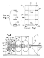
- Fig. 1 illustrates in plan view a typical carton blank 20 as currently produced on flexographic printer slotter machines.
- the carton blanks are made from sheets of corrugated paperboard or the like by printing, scoring, and slotting the paperboard sheets at pre-arranged locations. Each of these operations may be carried out in consecutive sections in the same machine.
- the scoring and slotting operations define flaps which are later folded over to form finished cartons.
- the carton blank 20 has score lines 22, slots 24, and cut-outs 26.
- the slots 24 define end flaps 28, the score lines 22 define side panels 30, and the cut-outs 26 define a stitch flap 32, sometimes called a glue flap, which is stitched, glued or stapled to the opposite end side panel 30 when the carton blank is erected into a carton.
- Each cut-out 26 is formed by cutting a slot, such as one of the slots 24, in conjunction with making a cross-cut with a serrated bevelled edge knife to complete the edge 34 of the cut-out 26.
- Fig. 2 illustrates the scrap produced when making the slots 24 and the cut-out 26 in the left-hand side of the blank of Fig. 1.
- the cutting of each slot 24 produces a narrow strip 36 of scrap.
- the production of each cut-out 26 produces two separate pieces of scrap; firstly a narrow slot strip 38, similar to the strips 36, and secondly a larger rectangular piece 40.
- the strips 36 become wedged in grooves in female cutter heads and so can be controlled.
- the larger scrap pieces 40 tend to be thrown off and away from the associated cutter head and are usually randomly scattered in and around the carton blank manufacturing machine. This creates obvious inconvenience as is well known.
- the present invention is concerned with eliminating or mitigating this inconvenience, and produces the scrap strip 38 and the larger scrap piece 40 as a single integral piece of scrap as illustrated in Fig. 13.
- Fig. 3 diagrammatically illustrates a typical carton blank manufacturing machine 42 modified in accordance with the present invention.
- the machine 42 supports a stack 44 of paperboard sheets in a sheet feed section 46. This is followed by one or more printing sections of which two sections 48 and 50 are shown and through which a sheet 52 is shown being fed and printed. A pair of pull rolls 53 guide and advance the sheet 52 from the printing section 50. Finally, at the discharge end of the machine, are scoring and slotting sections 54 and 56.
- the scoring section 54 has a scoring shaft 58 carrying upper creaser heads 59 upon which are male creasing contours (not visible in Fig. 3) which cooperate with a resilient covering (not visible in Fig. 3) on lower creaser heads 61 carried on shaft 60.
- the final slotting section 56 has an upper shaft 62 with male slotter heads 63 and a lower shaft 64 with female slotter heads 65.
- Each male slotter head 63 carries two slot cutting blades 66 and 68. All the various rolls are geared together and rotate in the directions indicated by arrows to successively feed paperboard sheets from the stack 44 through the machine 42 from right to left in Fig. 3.
- the slot cutting blades 66, 68 (hereinafter called "slotter blades”) on one upper slotter head 63 at one end of the shaft 62 and the female slotter blades 110 on lower slotter head 65 cooperating therewith are modified according to the invention by the provision of scallop-like cavities 70, 72 as will be described below.
- the slotter blades 66 and 68 associated with the end male slotter head (also called a stitch flap head) at which the stitch flap is formed, are similar but adapted so that the blade 68 makes a leading slot cut and the blade 66 a trailing slot cut in each carton blank. Both blades 66, 68 preferably have a serrated bevelled edge knife associated therewith for completing the cutting of the stitch flap, although a bevelled non-serrated knife may be used if desired.
- the leading slotter blade 68 and its associated serrated knife will now be described in greater detail with reference to Figs. 4 to 7.
- Fig. 4 shows in side elevation the leading slotter blade 68 and its associated serrated knife 74.
- the blade 68 is formed as a sector of an annulus and is secured on the end male slotter head 76 of the shaft 62 by three bolts 78.
- the lower cutting edge of the knife 74 is serrated and bevelled to a sharp cutting edge.
- the knife 74 is diagrammatically shown mounted in a knife holder bracket 80 secured by bolts 82 to the slotter head 76.
- the various methods of mounting a serrated knife on a slotter head are well known, including the adjustability of the arcuate location of the knife relative to the slotting blade and the setting of the angle at which the plane of the serrated knife extends from the vertical outer face of the slotter blade, and therefore do not require further description here.
- the blade 68 has an inner arcuate edge 84 and a longer outer arcuate edge 86.
- the scallop-like cut-out 72 is machined out of the steel blade 68 at a location partway along the outer arcuate edge 86 intermediate the ends thereof.
- the cut-out 72 starts about the midpoint of the arcuate edge 86 and extends for about a quarter to a third of the length of the arcuate edge 86, and may be up to about a half of the arcuate edge 86, finishing a short distance before the trailing edge 88 of the blade.
- the cut-out 72 extends both into the thickness of the blade 68 and about a quarter to a third of the radial distance towards the inner arcuate edge 84.
- the radially inner boundary of the cut-out 72 is defined in the outer face of the blade 68 by the curve 90 which is shown asymmetric, but for convenience of manufacture may be symmetric about its mid-point.
- the curve 90 smoothly leaves and rejoins the arcuate edge 86 at junction points 94 and 96, respectively, and has a curved peak 92 shown closer to the leading junction 94 than to the trailing junction 96.
- Fig. 5 is a view of the radially outer edge 86 of the blade 68 taken in the direction of the arrow 5 in Fig. 4.
- the scallop-like cut-out 72 extends well over halfway through the thickness of the blade 68. From the leading junction 94, the inner surface of the cut-out 72 curves into the thickness of the blade, and then, after a flat section 98 parallel to the general plane of the blade, curves back out to the junction point 96. At the flat section 98, the blade may be reduced to one third to one fifth of its thickness, or even less, for example a three eighths of an inch thick blade may be reduced to .065 to .125 inch.
- Fig. 6 is a section of the blade 68 on the line 6-6 of Fig. 4.
- the top 92 of the cut-out 72 curves smoothly into the outer face of the blade 68.
- the bottom of the cut-out 72 is shown extending about two thirds into the thickness of the blade, leaving the blade at that location with only a narrow portion 100 of the outer arcuate edge 86.
- the inner bounding wall of the cut-out 72 at its sides and upper portion blends arcuately and smoothly with the outer face of the blade 68. These blending surfaces may each commence convexly and then make a transition to being concave.
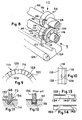
- Fig. 7 is a perspective view of the blade and cutter assembly of Fig. 4.
- the scallop-like cut-out 72 can be seen together with the flat section 98 of its inner. surface.
- the knife 74 has a serrated bottom cutting edge 102, and can be seen extending transversely from the outer surface of the blade 68 at a rear location spaced rearwardly from the cut-out 72.
- the knife 74 forms a cross-cut knife.
- the blade 66 (Fig. 3) and its associated serrated knife are similarly constructed.
- Fig. 8 is a simplified perspective representation of the slotting and cutting section 56 of the machine of Fig. 3, showing the left-hand outer end of that section, that is left-hand when facing in the forward direction of the machine which in Fig. 3 is from right to left.
- the slotter blades 66, 68 are mounted on the male slotter head 76 which is rigidly secured on the shaft 62.
- a cooperating female slotter head 108 is rigidly secured on the shaft 64 and forms a nip with the male slotter head 76, through which nip the carton blanks being processed are sequentially fed.
- the female slotter head includes relatively thick and thin discs, 110 and 112, respectively, defining an annular groove 114 therebetween and having a backing-up cutting edge 116 on opposite sides; these edges 116 are the radially outer peripheral cutting edges of the groove 114.
- Juxtaposed to the thin disc 112 is an anvil 118 having a resilient cover 120 slidably mounted thereon.
- a stripper blade 122 is resiliently mounted on a support bar 124 and penetrates into the groove 114 to the bottom thereof against which it is resiliently urged.
- the stripper blade 122 fits around an arcuate portion of the bottom of the groove 114, substantially fills the axial width of the groove 114, and has a knife-like leading axial edge which cooperates with the bottom of the groove 114 to remove any paperboard scrap engaged therein.
- the paperboard scrap so removed drops onto an endless conveyor belt 126 extending across the width of the section 56 below the lower slotter head 108 and the support bar 124.
- the conveyor belt 126 deposits this scrap in a suitable collection system at the other side of the machine.
- a hardened and ground rigid anvil may be used in place of the resilient anvil 118 against which a non-serrated bevelled edge blade is used to make the transverse cut for completing the stitch flap.
- the slotter blades 68, 66 successively enter the groove to cut respectively leading and trailing slots in each carton blank as it is fed through the section 56 between the rotating male and female slotter heads 76, 108.
- the blades 68, 66 are a close fit in the groove 114, and the outer peripheral arcuate edges of these blades cooperate with the peripheral backing-up cutting edges 116 of the groove 114 to make two parallel cuts in the paperboard, one each side of the slot being cut therein.
- the scrap strip so cut-out is forced by the slotting blades 68, 66 into the bottom of the groove 114 from where it is removed by the stripper blade 122.
- the cross-cut serrated knives associated with the slotting blades 68, 66 cooperate with the resiliently covered anvil 118 to make transverse cuts through the carton blanks to form the leading and trailing edges of the stitch flaps.
- the serrated blades penetrate into the resilient cover 120 during this cutting operation, the cover 120 rotatably sliding on the anvil 118 during this penetration to reduce damage to the cover 120.
- the scrap slot strip is wedged in the bottom of the groove 114, these integrally connected scrap portion and strip are carried by the groove 114 to the stripper blade 122 which removes the scrap slot strip and deposits the integrally connected scrap portion and strip onto the conveyor 126.
- the female slotter blades 110, 112 are modified to aid conveyance of the integral scrap portion and strip to the stripper blade 122, and to reduce any tendency for the stitch flap scrap portion to pull the integral scrap strip out of the groove 114. This modification is illustrated in Figs. 9 and 10.
- Fig. 9 is an end view, in the direction of the arrow 9 in Fig. 8, of an arcuate portion of the groove bounding annular side surface of the thicker disc 110.
- This surface has shallow and narrow radially extending channels 128 formed therein at equal intervals around the entire annular surface.
- the channels 128 extend outwardly from the bottom of the female cutting groove 114 (Fig. 8) and stop just short of the peripheral backing-up cutting edge 116 of the disc 110.
- the channels 128 have radially outer closed ends 129.
- the opposed surface of the thinner disc 112 (Fig. 8), forming the other side of the female cutting groove 114 has similarly formed outwardly extending channels which are arranged axially opposite the channels 128.
- Fig. 10 is a top view of a fragment of the female slotter head 108 looking downwardly in Fig. 8 in the direction of the arrow 10.
- Opposed identical radial channels 128 of rectangular cross-section, one in the thicker disc 110 and the other in the thinner disc 112, can be seen in broken lines disposed on each side of the female cutting groove 114.
- the channels 128 are show in broken lines as their radially outer ends are closed to provide a continuous radially outer peripheral cutting edge on each side of the groove 114 for cutting cooperation with the male slotter blades 66, 68.
- the scrap strip cut out by one of the male slotter blades 66, 68 is forced thereby into the female cutting groove 114, this scrap strip is somewhat compressed and extends into the radial channels 128 to relieve such compression.
- the radial channels 128 thus positively grip the edges of the scrap strip and positively convey this strip, with its integrally attached stitch flap scrap portion, to the cam-like stripper blade 122.
- the closed radially outer ends of the channels 128 further positively retain the scrap strips in the groove 114 until stripped out.
- the channels 128 are spaced apart at 15 degree intervals around each side of the groove 114.
- arcuately extending relief channels concentric with the axis of rotation of the female slotter head, are not as satisfactory as scrap tends to become lodged therein and is reluctant to clear.
- outwardly extending relief channels preferably radially extending channels, a self-clearing action occurs when the scrap strip is removed by the stripper blade 122.
- Fig. 11 illustrates diagrammatically the action of the scallop-like cut-out in each slotter blade 66, 68 upon a carton blank when the scallop-like cut-out enters the female cutting groove 114.
- the slotter blade 68 partially illustrated corresponds to the view of the blade 68 in Fig. 6.
- the carton blank 130 is cut by the scissor-type action between. the left-hand side peripheral cutting edge of the groove 114 and the cooperating left-hand arcuate cutting edge 132 of the blade 68.
- no scissor-type cutting action occurs on the right-hand side of the female cutting groove 114 in Fig. 11.
- the cut-out 72 allows the paperboard of the blank 130 below the blade 68 to be bent down into the groove 114 while still remaining attached to the portion 134 to the right.
- the portion 134 is in fact the stitch flap scrap portion cut from the blank 130 by the associated serrated knife 74 (Fig. 7).
- Fig. 1.2 shows a similar view to Fig. 11 but illustrating the action of a stitch flap, slotter blade 136 as used in the prior art without the scallop-like cut-out of the present invention.
- Both peripheral arcuate edges of the blade 136 cooperate in a scissor-type action with both cutting edges of the female cutting groove to cut the strip 38 from the blank.
- this scrap strip 38 is forced by the blade 136 into the female cutting groove, the stitch flap scrap portion 40 is left free to be thrown off into or around the machine.
- the slotter blades 66, 68 of the present invention while only having a single edge slit cutting action in the vicinity of the cut-outs 70, 72, have a double edge cutting action as illustrated in Fig. 12 peripherally before and after the cut-outs 70, 72.
- the scallop-like shape of the cut-outs 70, 72 facilitates a smooth transition from double edge cutting action to the single edge cutting action and then back again to double edge cutting action.
- Fig. 13 shows, in plan view, an integral piece of scrap produced in cutting a stitch flap in accordance with the present invention.
- a scrap strip 138 produced by the slot cutting action of the blade 68 is integrally connected by a bridging piece 140 to the larger scrap portion 134 cutoff by the serrated knife 74 in forming an edge of the stitch flap.
- the bridging piece 140 is provided by the single edge cutting of the blade 68 in the vicinity of the cut-out 72, as illustrated in Fig. 11.
- the strip 138 in Fig. 13 corresponds to the scrap strip 38 in Fig. 2
- the scrap portion 134 in Fig. 13 corresponds to the scrap portion 40 in Fig. 2.
- the scrap portion 134 is controlled according to the present invention by being carried along with the strip 138 which is wedged in the groove 114 of the female slotter head 108.
- the bridging piece 140 is best kept fairly short in comparison with the length of the strip 138. If the bridging piece 140 is too long, there is a tendency for the stiffness of the bridging piece to cause the strip 138 to lift in the groove 114 and become dislodged therefrom.
- a convenient length of the bridging piece 140 is less than about one half, and preferably between one third and one quarter, of the length of the strip 138.
- Fig. 14 is a similar view to Fig. 13 of the shape of the integral piece of scrap produced when cutting a differently shaped stitch flap in accordance with the invention.
- the serrated knife 102 (Fig. 7) would have been adjusted to a position intermediate the length of the slot cutting blade. Also, the serrated knife would have been adjusted to extend backwardly at an acute angle to the general plane of the slot cutting blade to produce the angled edge 142. As can be seen, the bridging piece 140 is further to the left than in Fig. 13.
- the two edge cutting of a slot cutting blade is changed to one edge cutting over a fraction of the cutting length of the blade. This, in conjunction with the knife cut transverse to the blade and the positioning thereof, produces the integral piece of scrap having a bridging piece.
- the present invention includes shaping or cutting an end of a carton blank in such a way as to form an integral piece of scrap having a bridging piece enabled by a scalloped cutting blade cooperating with another cutting blade.
Abstract
Description
- This invention relates to cutting carton blanks, particularly to slot cutting, and cutter arrangements therefor.
- In the corrugated paperboard industry it is well known to perform slotting operations, for example in the production of carton blanks to define flaps thereof. For example, rotary slot cutting heads for performing such operations are disclosed in United States Patents Nos. 3,518,922 and 3,540,357. It is also known to employ cross-cut knives to make transverse cuts adjacent slots to form a stitch flap at one end of carton blanks. An example of a cross-cut knife is disclosed in United States Patent No. 4,295,842.
- One of the problems associated with these slotting operations, particularly when associated with cross-cutting to form a stitch flap, is control and removal of the scrap produced. U.S. Patent 4,295,842 referred to above discloses an arrangement for removing paperboard scrap.
- Apparatus for slotting and cutting carton blanks is frequently incorporated in flexographic printer slotter machines which produce finished printed carton blanks from sheets of corrugated paperboard.
- The present invention is concerned generally with controlling the scrap produced when making slot cuts, particularly when making combined slot and cross cuts in a paperboard sheet or the like. The invention is particularly concerned with controlling scrap when forming a stitch flap in a carton blank.
- It is an object of the present invention to produce integrally connected portions of scrap when cutting and/or shaping an end of a carton blank, such as when forming one end of a stitch flap, using combined slot and cross cuts.
- A feature by which this is achieved is the provision of a cut-out in a side of a slot cutting blade to enable a bridging piece to be left between the strip-like portion of scrap from the slot cut and another portion of scrap formed between the slot cut and a cross cut.
- This has the advantage that by controlling the strip-like portion of scrap, the other portion of scrap is automatically controlled as it is integrally attached to the strip-like portion by the bridging piece. The strip-like scrap portion can be controlled by causing it to wedge in the groove of a female slot cutting head, and then positively removing it from this groove, for example by a cam-like blade engaged in the groove with a conveyor therebelow.
- An optional feature of the preferred embodiment of the invention is to provide for more positive control of strip-like scrap in the cutting groove of a female slot cutting head. This is achieved by forming outwardly extending, preferably radial, channels in the side walls of the groove. This has the advantage of allowing edges of the strip-like scrap to expand into these channels so keying the strip-like scrap in the groove until stripped therefrom.
- Accordingly, therefore, there is provided by one aspect of the present invention an apparatus for forming a stitch flap in a carton blank, comprising a rotatably driven male cutting head cooperating with a rotatably driven female cutting head. The female cutting head has a peripheral cutting groove therein and an anvil surface adjacent one side of this groove. The male cutting head has a two edged slot cutting blade of predetermined arcuate length which enters the groove, and a knife which extends transversely away from the blade and engages the anvil surface. The blade has a cut-out in one side thereof adjacent said one side of the groove and extending along a portion of said arcuate length, this cut-out modifying the blade to a single edged cutting blade along said portion, whereby scrap portions produced from the carton blank by a slotting cut of the blade and a transverse cut of the knife are connected together by a bridging piece enabled by the cut-out.
- Advantageously, said portion of said arcuate length is intermediate ends of the predetermined arcuate length of the blade. This portion is preferably spaced inwardly from both ends of the blade, and is preferably not greater than one half of said arcuate length.
- The cut-out may be of scallop-like form, and preferably has an inner surface comprising convex and concave smoothly merging sections to provide for smooth operation of the blade in changing between double and single edge cutting.
- According to another aspect of the invention, there is provided a method of cutting an end portion of a carton blank comprising the steps of cutting a slot in the carton blank adjacent one end of the carton blank, the slot having a lengthwise direction and being incomplete on one side for a portion of the length thereof, making a cut in the carton blank transverse to said direction, the slot cutting and cut making steps together severing from the carton blank an integral piece of scrap comprising a strip portion connected to another portion by a bridging piece created by the slot being incomplete on one side , and collecting the integral piece of scrap. The slot cutting and cut making steps may be performed at the same time or either performed before the other
- Other objects, features and advantages of the present invention will become more fully apparent from the following detailed description of the preferred embodiment, the appended claims and the accompanying drawings.
- In the accompanying drawings:
- FIG. 1 illustrates in plan view a typical carton blank made in accordance with the prior art;
- FIG. 2 illustrates the scrap produced from the lefthand side of the carton blank of Fig. 1 during its production in accordance with the prior art;
- FIG. 3 is a diagrammatic representation in side elevation of a carton blank manufacturing machine incorporating the present invention, the near side frame members and covers and other parts having been omitted for simplicity and clarity and some parts shown in section;
- FIG. 4 is a fragmentary side elevation of an end male cutter head of the machine of Fig. 3 showing a stitch flap slot cutter and knife assembly according to the invention;
- FIG. 5 is an outside edge view of the slot cutting blade of Fig. 4 taken in the direction of the
arrow 5 in Fig. 4; - FIG. 6 is a section of the slot cutting blade of Figs. 4 and 5 taken on the line 6-6 in Fig. 4;
- FIG. 7 is a perspective view of the slot cutter and knife assembly of Fig. 4;
- FIG. 8 is a simplified perspective view of a near side portion of the left-hand section of the machine of Fig. 3;
- FIG. 9 is a fragmentary side elevational view of one of two discs of a female cutter head of the machine section of Fig. 8;
- FIG. 10 is a fragmentary top view of the two discs making up a female cutter head of the machine section of Fig. 8;
- FIG. 11 is a diagrammatic representation, in cross-section, of the slot cutting blade of Figs. 4 to 7 making a stitch flap cut in a carton blank in accordance with the invention;
- FIG. 12 is a similar view to Fig. 11 illustrating the same cut in accordance with the prior art;
- FIG. 13 is a plan view of the integrally formed piece of scrap that is produced when cutting a stitch flap in accordance with the invention; and
- FIG. 14 is a similar view to Fig. 13 of the integral piece of scrap produced in accordance with the invention when cutting a differently shaped stitch flap.
- Fig. 1 illustrates in plan view a typical carton blank 20 as currently produced on flexographic printer slotter machines. The carton blanks are made from sheets of corrugated paperboard or the like by printing, scoring, and slotting the paperboard sheets at pre-arranged locations. Each of these operations may be carried out in consecutive sections in the same machine. The scoring and slotting operations define flaps which are later folded over to form finished cartons. The carton blank 20 has
score lines 22,slots 24, and cut-outs 26. Theslots 24 defineend flaps 28, thescore lines 22 defineside panels 30, and the cut-outs 26 define astitch flap 32, sometimes called a glue flap, which is stitched, glued or stapled to the oppositeend side panel 30 when the carton blank is erected into a carton. Each cut-out 26 is formed by cutting a slot, such as one of theslots 24, in conjunction with making a cross-cut with a serrated bevelled edge knife to complete theedge 34 of the cut-out 26. - Fig. 2 illustrates the scrap produced when making the
slots 24 and the cut-out 26 in the left-hand side of the blank of Fig. 1. The cutting of eachslot 24 produces anarrow strip 36 of scrap. The production of each cut-out 26 produces two separate pieces of scrap; firstly anarrow slot strip 38, similar to thestrips 36, and secondly a largerrectangular piece 40. Thestrips 36 become wedged in grooves in female cutter heads and so can be controlled. However, thelarger scrap pieces 40 tend to be thrown off and away from the associated cutter head and are usually randomly scattered in and around the carton blank manufacturing machine. This creates obvious inconvenience as is well known. The present invention is concerned with eliminating or mitigating this inconvenience, and produces thescrap strip 38 and thelarger scrap piece 40 as a single integral piece of scrap as illustrated in Fig. 13. - Fig. 3 diagrammatically illustrates a typical carton
blank manufacturing machine 42 modified in accordance with the present invention. Themachine 42 supports astack 44 of paperboard sheets in asheet feed section 46. This is followed by one or more printing sections of which twosections sheet 52 is shown being fed and printed. A pair of pull rolls 53 guide and advance thesheet 52 from theprinting section 50. Finally, at the discharge end of the machine, are scoring and slottingsections scoring section 54 has a scoringshaft 58 carrying upper creaser heads 59 upon which are male creasing contours (not visible in Fig. 3) which cooperate with a resilient covering (not visible in Fig. 3) on lower creaser heads 61 carried on shaft 60. The final slottingsection 56 has anupper shaft 62 with male slotter heads 63 and alower shaft 64 with female slotter heads 65. Each male slotter head 63 carries twoslot cutting blades stack 44 through themachine 42 from right to left in Fig. 3. Theslot cutting blades 66, 68 (hereinafter called "slotter blades") on one upper slotter head 63 at one end of theshaft 62 and thefemale slotter blades 110 onlower slotter head 65 cooperating therewith are modified according to the invention by the provision of scallop-like cavities machine 42 are conventional and for further understanding thereof, particularly the manner of construction of the male and female slotter heads 63 and 65 onshafts - The
slotter blades blade 68 makes a leading slot cut and the blade 66 a trailing slot cut in each carton blank. Bothblades slotter blade 68 and its associated serrated knife will now be described in greater detail with reference to Figs. 4 to 7. - Fig. 4 shows in side elevation the leading
slotter blade 68 and its associatedserrated knife 74. Theblade 68 is formed as a sector of an annulus and is secured on the end male slotterhead 76 of theshaft 62 by threebolts 78. Also secured on the slotterhead 76, adjacent the trailing edge of theblade 68, is the thin,flat knife 74 which extends transversely from the general plane of theblade 68. The lower cutting edge of theknife 74 is serrated and bevelled to a sharp cutting edge. Theknife 74 is diagrammatically shown mounted in aknife holder bracket 80 secured bybolts 82 to the slotterhead 76. The various methods of mounting a serrated knife on a slotter head are well known, including the adjustability of the arcuate location of the knife relative to the slotting blade and the setting of the angle at which the plane of the serrated knife extends from the vertical outer face of the slotter blade, and therefore do not require further description here. Theblade 68 has an innerarcuate edge 84 and a longer outerarcuate edge 86. The scallop-like cut-out 72 is machined out of thesteel blade 68 at a location partway along the outerarcuate edge 86 intermediate the ends thereof. As shown, the cut-out 72 starts about the midpoint of thearcuate edge 86 and extends for about a quarter to a third of the length of thearcuate edge 86, and may be up to about a half of thearcuate edge 86, finishing a short distance before the trailingedge 88 of the blade. The cut-out 72 extends both into the thickness of theblade 68 and about a quarter to a third of the radial distance towards the innerarcuate edge 84. The radially inner boundary of the cut-out 72 is defined in the outer face of theblade 68 by thecurve 90 which is shown asymmetric, but for convenience of manufacture may be symmetric about its mid-point. Thecurve 90 smoothly leaves and rejoins thearcuate edge 86 atjunction points curved peak 92 shown closer to the leadingjunction 94 than to the trailingjunction 96. - Fig. 5 is a view of the radially
outer edge 86 of theblade 68 taken in the direction of thearrow 5 in Fig. 4. As can be seen, the scallop-like cut-out 72 extends well over halfway through the thickness of theblade 68. From the leadingjunction 94, the inner surface of the cut-out 72 curves into the thickness of the blade, and then, after aflat section 98 parallel to the general plane of the blade, curves back out to thejunction point 96. At theflat section 98, the blade may be reduced to one third to one fifth of its thickness, or even less, for example a three eighths of an inch thick blade may be reduced to .065 to .125 inch. - Fig. 6 is a section of the
blade 68 on the line 6-6 of Fig. 4. The top 92 of the cut-out 72 curves smoothly into the outer face of theblade 68. The bottom of the cut-out 72 is shown extending about two thirds into the thickness of the blade, leaving the blade at that location with only anarrow portion 100 of the outerarcuate edge 86. - As will be appreciated from Figs. 4, 5 and 6, the inner bounding wall of the cut-out 72 at its sides and upper portion blends arcuately and smoothly with the outer face of the
blade 68. These blending surfaces may each commence convexly and then make a transition to being concave. - Fig. 7 is a perspective view of the blade and cutter assembly of Fig. 4. The scallop-like cut-out 72 can be seen together with the
flat section 98 of its inner. surface. Theknife 74 has a serratedbottom cutting edge 102, and can be seen extending transversely from the outer surface of theblade 68 at a rear location spaced rearwardly from the cut-out 72. Theknife 74 forms a cross-cut knife. The blade 66 (Fig. 3) and its associated serrated knife are similarly constructed. - Fig. 8 is a simplified perspective representation of the slotting and cutting
section 56 of the machine of Fig. 3, showing the left-hand outer end of that section, that is left-hand when facing in the forward direction of the machine which in Fig. 3 is from right to left. Theslotter blades head 76 which is rigidly secured on theshaft 62. A cooperatingfemale slotter head 108 is rigidly secured on theshaft 64 and forms a nip with the male slotterhead 76, through which nip the carton blanks being processed are sequentially fed. The female slotter head includes relatively thick and thin discs, 110 and 112, respectively, defining anannular groove 114 therebetween and having a backing-upcutting edge 116 on opposite sides; theseedges 116 are the radially outer peripheral cutting edges of thegroove 114. Juxtaposed to thethin disc 112 is ananvil 118 having aresilient cover 120 slidably mounted thereon. Astripper blade 122 is resiliently mounted on asupport bar 124 and penetrates into thegroove 114 to the bottom thereof against which it is resiliently urged. Thestripper blade 122 fits around an arcuate portion of the bottom of thegroove 114, substantially fills the axial width of thegroove 114, and has a knife-like leading axial edge which cooperates with the bottom of thegroove 114 to remove any paperboard scrap engaged therein. The paperboard scrap so removed drops onto anendless conveyor belt 126 extending across the width of thesection 56 below thelower slotter head 108 and thesupport bar 124. Theconveyor belt 126 deposits this scrap in a suitable collection system at the other side of the machine. - As will be understood by those skilled in the art, a hardened and ground rigid anvil may be used in place of the
resilient anvil 118 against which a non-serrated bevelled edge blade is used to make the transverse cut for completing the stitch flap. - During operation, the
slotter blades section 56 between the rotating male and female slotter heads 76, 108. Theblades groove 114, and the outer peripheral arcuate edges of these blades cooperate with the peripheral backing-upcutting edges 116 of thegroove 114 to make two parallel cuts in the paperboard, one each side of the slot being cut therein. The scrap strip so cut-out is forced by the slottingblades groove 114 from where it is removed by thestripper blade 122. The cross-cut serrated knives associated with the slottingblades anvil 118 to make transverse cuts through the carton blanks to form the leading and trailing edges of the stitch flaps. The serrated blades penetrate into theresilient cover 120 during this cutting operation, thecover 120 rotatably sliding on theanvil 118 during this penetration to reduce damage to thecover 120. Due to the scalloped cut-outs slotter blades groove 114, these integrally connected scrap portion and strip are carried by thegroove 114 to thestripper blade 122 which removes the scrap slot strip and deposits the integrally connected scrap portion and strip onto theconveyor 126. - The
female slotter blades stripper blade 122, and to reduce any tendency for the stitch flap scrap portion to pull the integral scrap strip out of thegroove 114. This modification is illustrated in Figs. 9 and 10. - Fig. 9 is an end view, in the direction of the
arrow 9 in Fig. 8, of an arcuate portion of the groove bounding annular side surface of thethicker disc 110. This surface has shallow and narrow radially extendingchannels 128 formed therein at equal intervals around the entire annular surface. Thechannels 128 extend outwardly from the bottom of the female cutting groove 114 (Fig. 8) and stop just short of the peripheral backing-upcutting edge 116 of thedisc 110. Thus, thechannels 128 have radially outer closed ends 129. The opposed surface of the thinner disc 112 (Fig. 8), forming the other side of thefemale cutting groove 114, has similarly formed outwardly extending channels which are arranged axially opposite thechannels 128. - Fig. 10 is a top view of a fragment of the
female slotter head 108 looking downwardly in Fig. 8 in the direction of thearrow 10. Opposed identicalradial channels 128 of rectangular cross-section, one in thethicker disc 110 and the other in thethinner disc 112, can be seen in broken lines disposed on each side of thefemale cutting groove 114. Thechannels 128 are show in broken lines as their radially outer ends are closed to provide a continuous radially outer peripheral cutting edge on each side of thegroove 114 for cutting cooperation with themale slotter blades - During operation, when the scrap strip cut out by one of the
male slotter blades female cutting groove 114, this scrap strip is somewhat compressed and extends into theradial channels 128 to relieve such compression. Theradial channels 128 thus positively grip the edges of the scrap strip and positively convey this strip, with its integrally attached stitch flap scrap portion, to the cam-like stripper blade 122. The closed radially outer ends of thechannels 128 further positively retain the scrap strips in thegroove 114 until stripped out. Preferably thechannels 128 are spaced apart at 15 degree intervals around each side of thegroove 114. - It has been found that arcuately extending relief channels, concentric with the axis of rotation of the female slotter head, are not as satisfactory as scrap tends to become lodged therein and is reluctant to clear. However, by providing outwardly extending relief channels, preferably radially extending channels, a self-clearing action occurs when the scrap strip is removed by the
stripper blade 122. - Fig. 11 illustrates diagrammatically the action of the scallop-like cut-out in each
slotter blade female cutting groove 114. Theslotter blade 68 partially illustrated corresponds to the view of theblade 68 in Fig. 6. Thecarton blank 130 is cut by the scissor-type action between. the left-hand side peripheral cutting edge of thegroove 114 and the cooperating left-handarcuate cutting edge 132 of theblade 68. However, due to the scalloped relief formed by the cut-out 72 in the other side of theblade 68, no scissor-type cutting action occurs on the right-hand side of thefemale cutting groove 114 in Fig. 11. As can be seen, the cut-out 72 allows the paperboard of the blank 130 below theblade 68 to be bent down into thegroove 114 while still remaining attached to theportion 134 to the right. Theportion 134 is in fact the stitch flap scrap portion cut from the blank 130 by the associated serrated knife 74 (Fig. 7). - In contrast, Fig. 1.2 shows a similar view to Fig. 11 but illustrating the action of a stitch flap,
slotter blade 136 as used in the prior art without the scallop-like cut-out of the present invention. Both peripheral arcuate edges of theblade 136 cooperate in a scissor-type action with both cutting edges of the female cutting groove to cut thestrip 38 from the blank. Although thisscrap strip 38 is forced by theblade 136 into the female cutting groove, the stitchflap scrap portion 40 is left free to be thrown off into or around the machine. As will be appreciated, theslotter blades outs outs outs - Fig. 13 shows, in plan view, an integral piece of scrap produced in cutting a stitch flap in accordance with the present invention. A
scrap strip 138 produced by the slot cutting action of theblade 68 is integrally connected by abridging piece 140 to thelarger scrap portion 134 cutoff by theserrated knife 74 in forming an edge of the stitch flap. Thebridging piece 140 is provided by the single edge cutting of theblade 68 in the vicinity of the cut-out 72, as illustrated in Fig. 11. - In comparison with the scrap produced by the prior art as shown in Fig. 2, the
strip 138 in Fig. 13 corresponds to thescrap strip 38 in Fig. 2, and thescrap portion 134 in Fig. 13 corresponds to thescrap portion 40 in Fig. 2. However, due to thebridging piece 140 in Fig. 13, thescrap portion 134 is controlled according to the present invention by being carried along with thestrip 138 which is wedged in thegroove 114 of thefemale slotter head 108. - It has been found that the
bridging piece 140 is best kept fairly short in comparison with the length of thestrip 138. If thebridging piece 140 is too long, there is a tendency for the stiffness of the bridging piece to cause thestrip 138 to lift in thegroove 114 and become dislodged therefrom. A convenient length of thebridging piece 140 is less than about one half, and preferably between one third and one quarter, of the length of thestrip 138. - Fig. 14 is a similar view to Fig. 13 of the shape of the integral piece of scrap produced when cutting a differently shaped stitch flap in accordance with the invention. In the production of this, the serrated knife 102 (Fig. 7) would have been adjusted to a position intermediate the length of the slot cutting blade. Also, the serrated knife would have been adjusted to extend backwardly at an acute angle to the general plane of the slot cutting blade to produce the angled edge 142. As can be seen, the
bridging piece 140 is further to the left than in Fig. 13. - As will be appreciated, in cutting a stitch flap in accordance with the invention, the two edge cutting of a slot cutting blade is changed to one edge cutting over a fraction of the cutting length of the blade. This, in conjunction with the knife cut transverse to the blade and the positioning thereof, produces the integral piece of scrap having a bridging piece.
- It will be appreciated that the above incorporation of a bridging piece, between a scrap strip and another portion of scrap produced when slot cutting and/or shaping an end of a carton blank, can be employed other than for just forming stitch flaps. The present invention includes shaping or cutting an end of a carton blank in such a way as to form an integral piece of scrap having a bridging piece enabled by a scalloped cutting blade cooperating with another cutting blade.
- Further, the incorporation of outwardly extending channels, like the
channels 128, in the opposite side walls of other cutting grooves in female slotter heads, particularly female slotter heads along theshaft 64 in Figs. 3 and 8 intermediate the end female slotter heads, is also contemplated by the present invention. Such channels will similarly provide the advantage of more positively retaining and conveying the cut-out scrap strips in the female cutting grooves until stripped therefrom by appropriate stripper blades. - The above described embodiments, of course, are not to be construed as limiting the breadth of the present invention. Modifications, and other alternative constructions, will be apparent which are within the scope of the invention as defined in the appended claims.
Claims (21)
a rotatably driven male cutting head (76) cooperating with a rotatably driven female cutting head (108);
said female cutting head (108) having a peripheral cutting groove (114) therein and an anvil surface (120) adjacent one side of said groove (114);
said male cutting head (76) having a two edged slot cutting blade (68) of predetermined arcuate length which enters said groove (114), and a knife (74) which extends transversely away from said blade (68) and engages said anvil surface (120); and
said blade (68) having a cut-out (72) in one side thereof adjacent said one side of said groove and extending along a portion of said arcuate length (86), said cut-out modifying said blade (68) to a single edged cutting blade along said portion, whereby scrap portions produced from the carton blank by a slotting cut of said blade (68) and a transverse cut of said knife (74) are connected together by a bridging piece (140) enabled by said cut-out (72).
a rotatably driven male cutting head (76) cooperative with a rotatably driven female cutting head (108) to make slot cuts in carton blanks;
said female cutting head (108) having a peripheral groove (114) therein with opposed radially outer peripheral cutting edges (116);
said male cutting head (76) having a slot cutting blade (68) which enters said groove (114);
said groove (114) having opposed side walls with outwardly extending channels (128) therein; and
a stripper blade (122) engaging in said groove (114) to remove therefrom scrap pieces cut from the carton blanks and retained in said groove by said channels.
cutting a slot in the carton blank adjacent one end of the carton blank, the slot having a lengthwise direction and being incomplete on one side for a portion of the length thereof;
making a cut in said carton blank transverse to said direction;
said slot cutting and cut making steps together severing from the carton blank an integral piece of scrap comprising a strip portion (138) connected to another portion (134) by a bridging piece (140) created by said slot being incomplete on said one side for said portion; and
collecting said integral piece of scrap.
said one side is uncut at a location spaced along said slot in said direction intermediate ends of said slot;
said cutting step is performed by passing a rotating slot cutting blade (68) into and then out of a slot cutting groove (114); and
said collecting step comprises removing said scrap strip portion (138) from said groove (114) and allowing said integral piece of scrap to drop onto a conveyor (126).
Applications Claiming Priority (2)
| Application Number | Priority Date | Filing Date | Title |
|---|---|---|---|
| US944442 | 1986-12-19 | ||
| US06/944,442 US4725261A (en) | 1986-12-19 | 1986-12-19 | Cutting carton blanks and cutters therefor |
Publications (2)
| Publication Number | Publication Date |
|---|---|
| EP0272023A1 true EP0272023A1 (en) | 1988-06-22 |
| EP0272023B1 EP0272023B1 (en) | 1991-05-08 |
Family
ID=25481402
Family Applications (1)
| Application Number | Title | Priority Date | Filing Date |
|---|---|---|---|
| EP19870310669 Expired - Lifetime EP0272023B1 (en) | 1986-12-19 | 1987-12-03 | Cutting carton blanks and cutters therefor |
Country Status (4)
| Country | Link |
|---|---|
| US (1) | US4725261A (en) |
| EP (1) | EP0272023B1 (en) |
| JP (1) | JPS63173626A (en) |
| DE (1) | DE3769945D1 (en) |
Cited By (2)
| Publication number | Priority date | Publication date | Assignee | Title |
|---|---|---|---|---|
| EP0458340A2 (en) * | 1990-05-24 | 1991-11-27 | Mitsubishi Jukogyo Kabushiki Kaisha | Slitterscorer |
| CN107696579A (en) * | 2016-08-09 | 2018-02-16 | 宝艺新材料股份有限公司 | The adjustable print fluting machine of cutter and institute's toolsetting away from algorithm |
Families Citing this family (25)
| Publication number | Priority date | Publication date | Assignee | Title |
|---|---|---|---|---|
| US5090281A (en) * | 1990-03-08 | 1992-02-25 | Marquip, Inc. | Slitting apparatus for corrugated paperboard and the like |
| CA2077554C (en) * | 1990-03-08 | 2000-08-08 | Marquip, Inc. | Slitting apparatus for corrugated paperboard and the like |
| DE4141678A1 (en) * | 1991-12-17 | 1993-07-01 | Focke & Co | CARDBOARD PACKING AND METHOD AND DEVICE FOR PRODUCING THE SAME |
| US5386753A (en) * | 1993-05-14 | 1995-02-07 | Ward Holding Company, Inc. | Tab cutting |
| BR9610105A (en) * | 1995-08-10 | 1999-02-23 | Lawrence Paper Co | Grooving disc mechanism that has grooving blades that can be rotated selectively |
| US6026727A (en) * | 1996-03-07 | 2000-02-22 | Lawrence Paper Company | Rotary scoring apparatus having retractable scoring blade |
| US6059705A (en) * | 1997-10-17 | 2000-05-09 | United Container Machinery, Inc. | Method and apparatus for registering processing heads |
| US5964686A (en) * | 1997-11-07 | 1999-10-12 | Griffin Automation, Inc. | Method for forming slotted and creased box blanks |
| US6170231B1 (en) * | 1998-10-15 | 2001-01-09 | R. R. Donnelley & Sons Company | Apparatus for bulk cartoning of books |
| GB9915989D0 (en) * | 1999-07-09 | 1999-09-08 | Sullivan John A | Machine combination |
| CH694087A5 (en) * | 2000-03-30 | 2004-07-15 | Bobst Sa | Device for breaking attachment points connecting two edges of a cutting line. |
| US6682468B2 (en) * | 2001-11-07 | 2004-01-27 | Corrugated Gear & Services, Inc. | Rotating scoring head with curvilinear nib |
| US7111536B2 (en) * | 2001-12-24 | 2006-09-26 | Pitney Bowes Inc. | Mailpiece perforating/cutting system |
| JP3622056B1 (en) * | 2003-12-04 | 2005-02-23 | 近畿刃物工業株式会社 | Cutting tool |
| JP4805778B2 (en) * | 2006-09-27 | 2011-11-02 | 富士フイルム株式会社 | Packaging method and apparatus |
| JP4928912B2 (en) * | 2006-11-07 | 2012-05-09 | 吉野石膏株式会社 | Gypsum board manufacturing equipment scoring equipment |
| GB2451459B (en) * | 2007-07-28 | 2011-12-07 | Mansfield Board Machinery Ltd | Stitch flap cutting block |
| JP5448609B2 (en) * | 2009-06-30 | 2014-03-19 | キヤノン株式会社 | Cutting apparatus and image forming apparatus |
| JP5341644B2 (en) * | 2009-07-08 | 2013-11-13 | 三菱重工印刷紙工機械株式会社 | Slotter, slotter cutting method, slotter knife and tool post |
| FR2979328B1 (en) * | 2011-08-31 | 2014-05-16 | Martin | DEVICE FOR PROCESSING PLATE ELEMENT, PROCESSING UNIT AND PACKAGING MANUFACTURING MACHINE |
| US10315376B2 (en) * | 2012-11-08 | 2019-06-11 | The C.W. Zumbiel Company | System and associated method for digital scoring of carton blanks |
| CN103832002A (en) * | 2014-01-06 | 2014-06-04 | 蚌埠市振华包装机械有限责任公司 | Cleaning device on paperboard integrated forming machine |
| JP6228942B2 (en) * | 2015-01-14 | 2017-11-08 | 三菱重工印刷紙工機械株式会社 | Slotter head, slotter device, box making machine |
| SE540174C2 (en) * | 2015-11-25 | 2018-04-24 | Berg Ind Ab | Arrangement for cutting paper board sheets, and machine comprising said arrangement |
| CN109016659B (en) * | 2018-09-20 | 2024-01-05 | 杭州彭公包装有限公司 | Carton cutting optimization method |
Citations (3)
| Publication number | Priority date | Publication date | Assignee | Title |
|---|---|---|---|---|
| US3518922A (en) * | 1967-10-23 | 1970-07-07 | Koppers Co Inc | Blank stripping apparatus for rotary cutters |
| US3540357A (en) * | 1968-05-09 | 1970-11-17 | Ward Turner Machinery Co | Overlength extended slotter mechanism |
| DE2615463A1 (en) * | 1975-04-14 | 1976-10-28 | Koppers Co Inc | DEVICE FOR CHANGING THE ROTATIONAL POSITION OF A SLITTING DEVICE AND FOR CHANGING THE RELATIVE POSITION BETWEEN A FIXED AND A MOVABLE KNIFE CARRIER OF THE SLITTING DEVICE |
Family Cites Families (6)
| Publication number | Priority date | Publication date | Assignee | Title |
|---|---|---|---|---|
| US3033064A (en) * | 1959-01-12 | 1962-05-08 | Filemon T Lee | Support and stripper for cutter head in a paper shredding machine |
| GB1038267A (en) * | 1964-04-02 | 1966-08-10 | Ici Ltd | Chip cutter |
| US3353460A (en) * | 1965-05-21 | 1967-11-21 | Edward V Henc | Apparatus for working sheet material |
| US4295842A (en) * | 1979-12-31 | 1981-10-20 | The Ward Machinery Company | Stripping device for removing waste sheet board |
| JPS5895000A (en) * | 1981-11-30 | 1983-06-06 | 株式会社磯輪鉄工所 | Die cutter device |
| JPS60107327A (en) * | 1983-11-15 | 1985-06-12 | レンゴー株式会社 | Slotter |
-
1986
- 1986-12-19 US US06/944,442 patent/US4725261A/en not_active Expired - Fee Related
-
1987
- 1987-12-03 DE DE8787310669T patent/DE3769945D1/en not_active Expired - Lifetime
- 1987-12-03 EP EP19870310669 patent/EP0272023B1/en not_active Expired - Lifetime
- 1987-12-17 JP JP62317654A patent/JPS63173626A/en active Pending
Patent Citations (3)
| Publication number | Priority date | Publication date | Assignee | Title |
|---|---|---|---|---|
| US3518922A (en) * | 1967-10-23 | 1970-07-07 | Koppers Co Inc | Blank stripping apparatus for rotary cutters |
| US3540357A (en) * | 1968-05-09 | 1970-11-17 | Ward Turner Machinery Co | Overlength extended slotter mechanism |
| DE2615463A1 (en) * | 1975-04-14 | 1976-10-28 | Koppers Co Inc | DEVICE FOR CHANGING THE ROTATIONAL POSITION OF A SLITTING DEVICE AND FOR CHANGING THE RELATIVE POSITION BETWEEN A FIXED AND A MOVABLE KNIFE CARRIER OF THE SLITTING DEVICE |
Cited By (4)
| Publication number | Priority date | Publication date | Assignee | Title |
|---|---|---|---|---|
| EP0458340A2 (en) * | 1990-05-24 | 1991-11-27 | Mitsubishi Jukogyo Kabushiki Kaisha | Slitterscorer |
| EP0458340A3 (en) * | 1990-05-24 | 1992-05-06 | Mitsubishi Jukogyo Kabushiki Kaisha | Slitterscorer |
| CN107696579A (en) * | 2016-08-09 | 2018-02-16 | 宝艺新材料股份有限公司 | The adjustable print fluting machine of cutter and institute's toolsetting away from algorithm |
| CN107696579B (en) * | 2016-08-09 | 2019-04-19 | 宝艺新材料股份有限公司 | The adjustable print fluting machine of cutter and institute's toolsetting away from algorithm |
Also Published As
| Publication number | Publication date |
|---|---|
| DE3769945D1 (en) | 1991-06-13 |
| US4725261A (en) | 1988-02-16 |
| JPS63173626A (en) | 1988-07-18 |
| EP0272023B1 (en) | 1991-05-08 |
Similar Documents
| Publication | Publication Date | Title |
|---|---|---|
| EP0272023B1 (en) | Cutting carton blanks and cutters therefor | |
| US4596541A (en) | Slit-score method and apparatus | |
| US5641551A (en) | Multi-purpose rotary slit scorer and products formed thereby | |
| US5582571A (en) | Apparatus and method for perforating and creasing paperboard | |
| US4305716A (en) | Rotary die cutting machine having integral scrap stripper | |
| US3552244A (en) | Rotary die stripping | |
| JP3715432B2 (en) | Grooving blade with out-of-phase serration | |
| EP0624437B1 (en) | Apparatus for forming tabs on sheets | |
| US5140882A (en) | Assembly for severing sheet material | |
| US3977283A (en) | Rotary panel cutter for cutting openings in a web | |
| US5052992A (en) | Cut and score die apparatus and method | |
| KR20130041357A (en) | Trim-processing method in corrugating machine, corrugating machine, and edge-cutting device | |
| CA1101780A (en) | Rotatable cutter mechanism for cutting different length notches in a moving web | |
| GB2242151A (en) | Precrush tool for corrugated board slotter head | |
| US4151622A (en) | Groove cutting machine | |
| US5215516A (en) | Box making apparatus | |
| JP4523820B2 (en) | Slotter knife | |
| JPS6014699B2 (en) | suritsutaskoara | |
| JP2001287285A (en) | Slotter knife for corrugated fiberboard case manufacturing machine | |
| CN213798323U (en) | Paperboard slotting cutter and paperboard slotting machine | |
| CN112318591B (en) | Paperboard slotting cutter, paperboard slotting machine and paperboard slotting method | |
| JPS641073Y2 (en) | ||
| JPH0455834B2 (en) | ||
| EP0454468B1 (en) | Envelope blank forming machine | |
| CN210791311U (en) | Corrugated paper slotting cutter with special structure |
Legal Events
| Date | Code | Title | Description |
|---|---|---|---|
| PUAI | Public reference made under article 153(3) epc to a published international application that has entered the european phase |
Free format text: ORIGINAL CODE: 0009012 |
|
| AK | Designated contracting states |
Kind code of ref document: A1 Designated state(s): CH DE FR GB IT LI SE |
|
| 17P | Request for examination filed |
Effective date: 19880725 |
|
| 17Q | First examination report despatched |
Effective date: 19900117 |
|
| GRAA | (expected) grant |
Free format text: ORIGINAL CODE: 0009210 |
|
| AK | Designated contracting states |
Kind code of ref document: B1 Designated state(s): CH DE FR GB IT LI SE |
|
| REF | Corresponds to: |
Ref document number: 3769945 Country of ref document: DE Date of ref document: 19910613 |
|
| ET | Fr: translation filed | ||
| ITF | It: translation for a ep patent filed |
Owner name: SOCIETA' ITALIANA BREVETTI S.P.A. |
|
| PLBE | No opposition filed within time limit |
Free format text: ORIGINAL CODE: 0009261 |
|
| STAA | Information on the status of an ep patent application or granted ep patent |
Free format text: STATUS: NO OPPOSITION FILED WITHIN TIME LIMIT |
|
| 26N | No opposition filed | ||
| PGFP | Annual fee paid to national office [announced via postgrant information from national office to epo] |
Ref country code: FR Payment date: 19931109 Year of fee payment: 7 |
|
| PGFP | Annual fee paid to national office [announced via postgrant information from national office to epo] |
Ref country code: CH Payment date: 19931112 Year of fee payment: 7 |
|
| PGFP | Annual fee paid to national office [announced via postgrant information from national office to epo] |
Ref country code: SE Payment date: 19931117 Year of fee payment: 7 |
|
| PGFP | Annual fee paid to national office [announced via postgrant information from national office to epo] |
Ref country code: DE Payment date: 19931124 Year of fee payment: 7 |
|
| PGFP | Annual fee paid to national office [announced via postgrant information from national office to epo] |
Ref country code: GB Payment date: 19931129 Year of fee payment: 7 |
|
| PG25 | Lapsed in a contracting state [announced via postgrant information from national office to epo] |
Ref country code: GB Effective date: 19941203 |
|
| PG25 | Lapsed in a contracting state [announced via postgrant information from national office to epo] |
Ref country code: SE Effective date: 19941204 |
|
| PG25 | Lapsed in a contracting state [announced via postgrant information from national office to epo] |
Ref country code: LI Effective date: 19941231 Ref country code: CH Effective date: 19941231 |
|
| EAL | Se: european patent in force in sweden |
Ref document number: 87310669.4 |
|
| GBPC | Gb: european patent ceased through non-payment of renewal fee |
Effective date: 19941203 |
|
| PG25 | Lapsed in a contracting state [announced via postgrant information from national office to epo] |
Ref country code: FR Effective date: 19950831 |
|
| REG | Reference to a national code |
Ref country code: CH Ref legal event code: PL |
|
| PG25 | Lapsed in a contracting state [announced via postgrant information from national office to epo] |
Ref country code: DE Effective date: 19950901 |
|
| EUG | Se: european patent has lapsed |
Ref document number: 87310669.4 |
|
| REG | Reference to a national code |
Ref country code: FR Ref legal event code: ST |
|
| PG25 | Lapsed in a contracting state [announced via postgrant information from national office to epo] |
Ref country code: IT Free format text: LAPSE BECAUSE OF NON-PAYMENT OF DUE FEES;WARNING: LAPSES OF ITALIAN PATENTS WITH EFFECTIVE DATE BEFORE 2007 MAY HAVE OCCURRED AT ANY TIME BEFORE 2007. THE CORRECT EFFECTIVE DATE MAY BE DIFFERENT FROM THE ONE RECORDED. Effective date: 20051203 |