EP0271568B1 - Internal combustion engine using dynamic resonating air chamber - Google Patents
Internal combustion engine using dynamic resonating air chamber Download PDFInfo
- Publication number
- EP0271568B1 EP0271568B1 EP87904586A EP87904586A EP0271568B1 EP 0271568 B1 EP0271568 B1 EP 0271568B1 EP 87904586 A EP87904586 A EP 87904586A EP 87904586 A EP87904586 A EP 87904586A EP 0271568 B1 EP0271568 B1 EP 0271568B1
- Authority
- EP
- European Patent Office
- Prior art keywords
- piston
- chamber
- working face
- engine
- internal combustion
- Prior art date
- Legal status (The legal status is an assumption and is not a legal conclusion. Google has not performed a legal analysis and makes no representation as to the accuracy of the status listed.)
- Expired - Lifetime
Links
- 238000002485 combustion reaction Methods 0.000 title claims abstract description 242
- 239000000446 fuel Substances 0.000 claims abstract description 120
- 238000013459 approach Methods 0.000 claims description 30
- 238000012546 transfer Methods 0.000 claims description 27
- 230000000737 periodic effect Effects 0.000 claims description 22
- 238000000034 method Methods 0.000 claims description 14
- 238000009826 distribution Methods 0.000 claims description 13
- 230000008569 process Effects 0.000 claims description 8
- 238000007906 compression Methods 0.000 claims description 7
- 230000006835 compression Effects 0.000 claims description 7
- 229930195733 hydrocarbon Natural products 0.000 claims description 6
- UGFAIRIUMAVXCW-UHFFFAOYSA-N Carbon monoxide Chemical compound [O+]#[C-] UGFAIRIUMAVXCW-UHFFFAOYSA-N 0.000 claims description 5
- 229910002091 carbon monoxide Inorganic materials 0.000 claims description 5
- 238000013507 mapping Methods 0.000 claims description 5
- 238000012937 correction Methods 0.000 claims description 4
- 150000002430 hydrocarbons Chemical class 0.000 claims description 4
- 238000010791 quenching Methods 0.000 claims description 4
- 230000004044 response Effects 0.000 claims description 4
- 239000000463 material Substances 0.000 claims description 2
- 230000002093 peripheral effect Effects 0.000 claims description 2
- VLKZOEOYAKHREP-UHFFFAOYSA-N n-Hexane Chemical compound CCCCCC VLKZOEOYAKHREP-UHFFFAOYSA-N 0.000 claims 3
- 238000012545 processing Methods 0.000 claims 1
- 239000007789 gas Substances 0.000 description 15
- 150000003254 radicals Chemical class 0.000 description 9
- 230000000694 effects Effects 0.000 description 6
- 230000008901 benefit Effects 0.000 description 5
- 239000000203 mixture Substances 0.000 description 5
- 238000005086 pumping Methods 0.000 description 4
- 238000012360 testing method Methods 0.000 description 4
- 239000004215 Carbon black (E152) Substances 0.000 description 3
- QVGXLLKOCUKJST-UHFFFAOYSA-N atomic oxygen Chemical compound [O] QVGXLLKOCUKJST-UHFFFAOYSA-N 0.000 description 3
- 238000006243 chemical reaction Methods 0.000 description 3
- 238000004891 communication Methods 0.000 description 3
- 229910052760 oxygen Inorganic materials 0.000 description 3
- 239000001301 oxygen Substances 0.000 description 3
- 239000000126 substance Substances 0.000 description 3
- 241001125879 Gobio Species 0.000 description 2
- 230000001133 acceleration Effects 0.000 description 2
- 238000013461 design Methods 0.000 description 2
- 238000005516 engineering process Methods 0.000 description 2
- -1 hydrocarbon radicals Chemical class 0.000 description 2
- 230000006872 improvement Effects 0.000 description 2
- 230000003993 interaction Effects 0.000 description 2
- 239000007788 liquid Substances 0.000 description 2
- 238000010926 purge Methods 0.000 description 2
- 230000000171 quenching effect Effects 0.000 description 2
- 210000000707 wrist Anatomy 0.000 description 2
- 235000014676 Phragmites communis Nutrition 0.000 description 1
- 230000003044 adaptive effect Effects 0.000 description 1
- 230000004075 alteration Effects 0.000 description 1
- 238000004364 calculation method Methods 0.000 description 1
- 239000012141 concentrate Substances 0.000 description 1
- 238000011109 contamination Methods 0.000 description 1
- 238000001816 cooling Methods 0.000 description 1
- 238000011161 development Methods 0.000 description 1
- 230000002708 enhancing effect Effects 0.000 description 1
- 239000012530 fluid Substances 0.000 description 1
- 230000000977 initiatory effect Effects 0.000 description 1
- 238000002347 injection Methods 0.000 description 1
- 239000007924 injection Substances 0.000 description 1
- 238000004519 manufacturing process Methods 0.000 description 1
- 230000007246 mechanism Effects 0.000 description 1
- 238000012986 modification Methods 0.000 description 1
- 230000004048 modification Effects 0.000 description 1
- 238000005192 partition Methods 0.000 description 1
- 230000000644 propagated effect Effects 0.000 description 1
- 230000035484 reaction time Effects 0.000 description 1
- 238000009420 retrofitting Methods 0.000 description 1
- 238000007493 shaping process Methods 0.000 description 1
- XLYOFNOQVPJJNP-UHFFFAOYSA-N water Substances O XLYOFNOQVPJJNP-UHFFFAOYSA-N 0.000 description 1
Images


Classifications
-
- F—MECHANICAL ENGINEERING; LIGHTING; HEATING; WEAPONS; BLASTING
- F02—COMBUSTION ENGINES; HOT-GAS OR COMBUSTION-PRODUCT ENGINE PLANTS
- F02B—INTERNAL-COMBUSTION PISTON ENGINES; COMBUSTION ENGINES IN GENERAL
- F02B17/00—Engines characterised by means for effecting stratification of charge in cylinders
-
- F—MECHANICAL ENGINEERING; LIGHTING; HEATING; WEAPONS; BLASTING
- F02—COMBUSTION ENGINES; HOT-GAS OR COMBUSTION-PRODUCT ENGINE PLANTS
- F02F—CYLINDERS, PISTONS OR CASINGS, FOR COMBUSTION ENGINES; ARRANGEMENTS OF SEALINGS IN COMBUSTION ENGINES
- F02F3/00—Pistons
- F02F3/26—Pistons having combustion chamber in piston head
-
- F—MECHANICAL ENGINEERING; LIGHTING; HEATING; WEAPONS; BLASTING
- F02—COMBUSTION ENGINES; HOT-GAS OR COMBUSTION-PRODUCT ENGINE PLANTS
- F02B—INTERNAL-COMBUSTION PISTON ENGINES; COMBUSTION ENGINES IN GENERAL
- F02B17/00—Engines characterised by means for effecting stratification of charge in cylinders
- F02B17/005—Engines characterised by means for effecting stratification of charge in cylinders having direct injection in the combustion chamber
-
- F—MECHANICAL ENGINEERING; LIGHTING; HEATING; WEAPONS; BLASTING
- F02—COMBUSTION ENGINES; HOT-GAS OR COMBUSTION-PRODUCT ENGINE PLANTS
- F02B—INTERNAL-COMBUSTION PISTON ENGINES; COMBUSTION ENGINES IN GENERAL
- F02B23/00—Other engines characterised by special shape or construction of combustion chambers to improve operation
- F02B23/08—Other engines characterised by special shape or construction of combustion chambers to improve operation with positive ignition
-
- F—MECHANICAL ENGINEERING; LIGHTING; HEATING; WEAPONS; BLASTING
- F02—COMBUSTION ENGINES; HOT-GAS OR COMBUSTION-PRODUCT ENGINE PLANTS
- F02B—INTERNAL-COMBUSTION PISTON ENGINES; COMBUSTION ENGINES IN GENERAL
- F02B23/00—Other engines characterised by special shape or construction of combustion chambers to improve operation
- F02B23/08—Other engines characterised by special shape or construction of combustion chambers to improve operation with positive ignition
- F02B23/10—Other engines characterised by special shape or construction of combustion chambers to improve operation with positive ignition with separate admission of air and fuel into cylinder
-
- F—MECHANICAL ENGINEERING; LIGHTING; HEATING; WEAPONS; BLASTING
- F02—COMBUSTION ENGINES; HOT-GAS OR COMBUSTION-PRODUCT ENGINE PLANTS
- F02F—CYLINDERS, PISTONS OR CASINGS, FOR COMBUSTION ENGINES; ARRANGEMENTS OF SEALINGS IN COMBUSTION ENGINES
- F02F3/00—Pistons
- F02F3/28—Other pistons with specially-shaped head
-
- F—MECHANICAL ENGINEERING; LIGHTING; HEATING; WEAPONS; BLASTING
- F02—COMBUSTION ENGINES; HOT-GAS OR COMBUSTION-PRODUCT ENGINE PLANTS
- F02B—INTERNAL-COMBUSTION PISTON ENGINES; COMBUSTION ENGINES IN GENERAL
- F02B75/00—Other engines
- F02B75/02—Engines characterised by their cycles, e.g. six-stroke
- F02B2075/022—Engines characterised by their cycles, e.g. six-stroke having less than six strokes per cycle
- F02B2075/025—Engines characterised by their cycles, e.g. six-stroke having less than six strokes per cycle two
-
- F—MECHANICAL ENGINEERING; LIGHTING; HEATING; WEAPONS; BLASTING
- F02—COMBUSTION ENGINES; HOT-GAS OR COMBUSTION-PRODUCT ENGINE PLANTS
- F02B—INTERNAL-COMBUSTION PISTON ENGINES; COMBUSTION ENGINES IN GENERAL
- F02B75/00—Other engines
- F02B75/12—Other methods of operation
- F02B2075/125—Direct injection in the combustion chamber for spark ignition engines, i.e. not in pre-combustion chamber
-
- F—MECHANICAL ENGINEERING; LIGHTING; HEATING; WEAPONS; BLASTING
- F02—COMBUSTION ENGINES; HOT-GAS OR COMBUSTION-PRODUCT ENGINE PLANTS
- F02B—INTERNAL-COMBUSTION PISTON ENGINES; COMBUSTION ENGINES IN GENERAL
- F02B2275/00—Other engines, components or details, not provided for in other groups of this subclass
- F02B2275/40—Squish effect
-
- Y—GENERAL TAGGING OF NEW TECHNOLOGICAL DEVELOPMENTS; GENERAL TAGGING OF CROSS-SECTIONAL TECHNOLOGIES SPANNING OVER SEVERAL SECTIONS OF THE IPC; TECHNICAL SUBJECTS COVERED BY FORMER USPC CROSS-REFERENCE ART COLLECTIONS [XRACs] AND DIGESTS
- Y02—TECHNOLOGIES OR APPLICATIONS FOR MITIGATION OR ADAPTATION AGAINST CLIMATE CHANGE
- Y02T—CLIMATE CHANGE MITIGATION TECHNOLOGIES RELATED TO TRANSPORTATION
- Y02T10/00—Road transport of goods or passengers
- Y02T10/10—Internal combustion engine [ICE] based vehicles
- Y02T10/12—Improving ICE efficiencies
Definitions
- This invention relates to internal combustion piston engines and more specifically to a combustion chamber configuration and a combustion process having application in such engines.
- the invention described in the aforementioned U.S. patent comprises a combustion chamber geometry for an internal combustion engine that produces controlled burning of fuel by prolonging the supply of air to the combustion zone over the combustion/expansion part of the engine operating cycle.
- an air chamber disposed in the piston member of the engine is located adjacent the combustion chamber and communicates with the latter through a restricted passageway.
- the air chamber and passageway are configured to behave as a Helmholtz resonating chamber when driven by combustion vibrational wave energy during the operating cycle of the engine.
- the invention provides a process for carrying out combustion of an air and fuel charge in an internal combustion engine using a movable piston to vary an initially undivided combustion chamber volume defined at least in part by a working face of the piston and in which the charge is placed and combusted, the working face of the piston compressing at least the air portion of the charge in the undivided combustion chamber volume to a minimum volume at or near which ignition of the charge is initiated, characterized by:
- the present invention permits utilization of combustion wave energy to enhance the combustion process under conditions when establishment of a resonating air chamber within a piston is unfeasible or undesirable for any reason.
- the present invention contemplates the establishment of a resonating air chamber within the combustion chamber itself by dynamically dividing the combustion chamber area into two connected zones when the piston of the engine is at and near its minimum volume position, whereby the appropriate geometric and dimensional relationships are temporarily established to cause driving of an air chamber in resonance by combustion wave energy to cause periodic discharge of air from the chamber into the combustion zone where substantially all of the fuel of the charge being combusted is located.
- the resonating air chamber is established only when the moving piston of the engine is at and near its minimum volume position and does not otherwise exist within the combustion chamber.
- the charge is manipulated so that virtually all of the fuel of the charge is located within the first or "ignition" zone established in the divided combustion chamber, and air with an insignificant amount of fuel is in the second or “resonating" zone at the moment of ignition of the charge.
- Combustion vibrational wave energy generated in the ignition chamber drives the resonating chamber in resonance through a restricted connecting passageway that itself may be temporarily formed by the working face area of the piston as it approaches an adjacent fixed wall surface of the combustion chamber, or may be permanently provided in the combustion chamber.
- the invention reduces combustion chamber peak pressures, permits control of knock and reduces undesirable engine exhaust emissions.
- the invention has application in reciprocating and rotary piston engines, as well as Otto, Diesel, four-stroke and two-stroke combustion cycles. Since resonant wave interaction enables leaner combustion than conventional combustion cycles, the overall efficiency of the combustion process is improved.
- FIG. 1 a schematic illustration of a combustion chamber embodying the invention is shown within an internal combustion engine 10 comprising generally a block 12, a head 14, an intake port 16, an exhaust port 18, intake and exhaust valves 20, 22, respectively, a spark plug 24, and a fuel injector 26.
- a piston 28 is disposed in cylinder 30 for reciprocating movement and includes a working face 32 and a guide portion 34.
- the piston 28 is pivotally attached to a connecting rod 36 through a wrist pin or gudgeon 38 for transmitting motion and output power through an engine crankshaft (not shown).
- Appropriate water cooling chambers 40 may be provided within the block 12.
- the engine is a four-stroke Otto cycle engine
- its operating cycle will be well known to those skilled in the art, and includes intake, compression, expansion (working) and exhaust strokes for each operating cycle of the engine.
- air is aspirated through the intake port and fuel is admitted through fuel injector 26 in timed relationship with the operating cycle of the engine, whereby, at or near the end of the compression stroke of the piston 28, a full fuel/air charge is disposed between the working face 32 of the piston and the surrounding fixed walls of the block 12 and head 14.
- the charge is ignited by the spark plug 24 in appropriate timed relationship with the operating cycle of the engine, whereby reaction of the fuel and air above the working face of the piston releases heat energy to drive the piston in a direction causing expansion of the combustion chamber (downwardly as viewed in Figure 1) and to rotate the engine crankshaft to produce work.
- the combustion chamber is identified generally at 40 and constitutes the total volume defined by the working face 32 of the piston 28 and the fixed surfaces of the block 12 and head 14 defining the confines of the combustion chamber 40.
- the combustion chamber 40 is temporarily divided into two chambers A and B with a restricted passageway 42 connecting the chambers A and B. This is achieved by shaping the piston and the fixed combustion chamber walls so that when the piston approaches and is at its minimum volume position, an effective partition chambers A and B is formed.
- Chamber A is referred to as the "ignition” chamber having volume V A
- chamber b is referred to as the "resonating" chamber having volume V B .
- the relationships between the geometrical configurations of chambers A and B, as well as passageway 42 and working face 32 of the piston are critical to the achievement of the desired combustion cycle.
- Figure 2 illustrates a view taken along line 2-2 of Figure 1, showing the restricted passageway 42 between ignition chamber A and resonating chamber B.
- Figure 3 illustrates an exemplary embodiment of the working face 32 of piston 28. It will be observed from Figure 3 that the restricted passageway 42 is disposed between chambers A and B so that it terminates at one end in chamber A and at its other end in chamber B where the opposed wall surfaces begin to diverge.
- the shaded area 43 illustrates the length (from left to right as shown in Figure 3) and width (distance of passageway 42 over a segment of the working face of the piston having an arc length ⁇ ) of the passageway 42 as projected on the working face 32 of piston 28.
- the chambers A and B were connected by a restricted passageway or gap disposed around a circumferential length of the piston adjacent its working face, so that the volume B essentially remained constant during the operating cycle of the engine.
- Helmholtz resonance was induced in chamber B to produce periodic pumping of air from chamber B into chamber A via the restricted passageway throughout the combustion event.
- the present invention envisions a dynamic resonating chamber volume V B that is created only when the moving piston element approaches and is at its minimum volume position, thereby avoiding the need to provide a separate fixed air reservoir chamber within the piston or other engine component.
- Using a dynamic resonating chamber enables very rapid achievement of the pumping effect within the overall combustion chamber near and at the minimum volume position of the piston, producing smoother and more efficient combustion within a very brief time span as compared with the time span envisioned in the system described in patent No. 4.592.318.
- chamber A constitutes an ignition chamber and chamber B a resonating air reservoir chamber connected by a passageway 42 having a critical geometric configuration.
- FIG 4 there is illustrated a simple Helmholtz resonator chamber 44 having a "neck" portion 46.
- a resonant condition occurs wherein the gas will be excited at its Helmholtz resonant frequency and will remain excited with relatively low levels of input energy, provided that the resonance condition is maintained.
- the Helmholtz resonating chamber used in the invention therein described was constituted by a fixed volume chamber disposed within the piston, with the restricted passageway around the peripheral top portion of the piston constituting the "neck" of the resonating chamber.
- a portion of the resonating chamber 44 corresponding roughly with the shaded portion shown in Figure 4 is formed above the piston within the combustion chamber when the piston is at and near its minimum volume position as shown in Figure 5.
- the piston 28 is shown at its minimum volume position (TDC) and volume B has been established to satisfy requirements for a Helmholtz resonator to be driven in resonance by periodic combustion wave energy in adjacent chamber A.
- While a generally upwardly arched spherical surface 48 is seen to define volume V B above the working face 32 of piston 28 in Figure 5, it is to be understood that various other configurations of surface 48 are envisioned by this invention to enable custom designing of Helmholtz resonator chambers in virtually any type of engine. Moreover, the invention contemplates utilizing different curvatures of resonating chamber walls (both fixed wall surfaces and moving piston wall surfaces) as well as ignition chamber walls to enable proper tuning of the chambers and the achievement of the wave interaction effect resulting from the invention. It is to be understood that the invention has particular application in a retrofit situation in which minimum alteration to existing engine components is desired or possible.
- the curvature of the upper surface of the resonator chamber B can be generally arched upwardly as shown in Figure 5, within the limits of the formula: (1) d 2 y d x 2 ⁇ 0 where coordinates x and y respectively lie on orthogonal lines extending perpendicular and parallel to the primary direction of motion of the working face 32 of the piston 28 as it approaches adjacent fixed wall section 48 of chamber B at and near its minimum volume position.
- abscissa x generally lies on a line extending parallel to a line connecting chambers A and B through restricted passageway 42
- ordinate y lies on a line extending generally parallel to the primary direction of motion of piston 28 relative to fixed surface 48.
- curvature of surface 48 in accordance with Formula (2) results in a curve that arches downwardly within the frame of reference of coordinates x and y, and forms a curvature that would "retain a liquid substance.” It must be kept in mind that the curvatures of surface 48 herein described must be viewed as curved lines within the coordinates x and y as shown in Figure 5 which may be considered as being “arched” upwardly or downwardly, “concave”, “convex” or flat, depending upon the point of view from which the surfaces are observed.
- the working face 32 of piston 28 can be recessed as shown at 50 to define at least a part of chamber B.
- surface 50 can be described by te limiting conditions of formula (2) (arched downwardly).
- a portion of the restricted passageway 42 can be formed by an undercut portion 52 of working face 32 of piston 28.
- both a portion of the restricted passageway 42 and part of chamber B is formed by undercut portions 50,52 of piston 28.
- piston 28 is provided with an outwardly protruding portion 54 which, as piston 28 approaches its minimum volume position, tends to cause whirling motion of gas in chamber B.
- passageway 42 is not disposed between working face 32 of piston 28 and the adjacent fixed surfaces of combustion chamber 40, but rather is provided in the form of an aperture within a fixed abutment element 55 that may be integrally formed as an extension of upper surfaces 48 and 56 of chambers B and A, respectively, or which may be formed as a separate attachment secured to the upper end of the combustion chamber 40 by appropriate securing means (not shown).
- the profiles of the fixed wall 56 of ignition chamber A can be defined by the formulas (1), (2) and (not illustrated) (3).
- the working face of piston 28 constituting at least part of chamber A also can be configured in accordance with formulas (1), (2) and (3).
- recessed portion 58 of piston 28 is contoured to provide desired volume V A in chamber A to achieve the certain ratios needed to establish volumetric relationships between chambers A and B and to provide other benefits, such as, for example, better concentration of fuel in chamber A.
- FIG. 13 illustrates a typical preferred embodiment of the invention and in particular enables a detailed observation of the geometric relationships between elements constituting combustion chamber 40 at and near its minimum volume condition.
- combustion chamber 40 is temporarily divided into an ignition chamber A having volume V A and a resonating chamber B having a volume V B when piston 28 is at and near its minimum volume position.
- Chambers A and B are connected by a restricted passageway 42 defined in part by a fixed wall section 60 and, in this embodiment, a portion of the working face 32 of piston 28.
- Passageway 42 has an average transverse dimension g (between working face 32 of piston 28 and the adjacent fixed wall of the combustion chamber) across its width (left to right in Figure 2) measured approximately perpendicular to its, length L which extends generally along a diametrically extending line connecting chambers A and B. As shown in Figure 2, the transverse dimension g may not be constant over entire width of passageway 42, depending upon the geometric configuration of the passageway. Passageway 42, moreover, has a cross-sectional area S measured in a transverse plane extending across distance g and the width of the passageway (i.e., a vertical plane through passageway 42 in the plane of Figure 2). The volume V P of the passageway, therefore, would be defined as S x L.
- passageway 42 is configured to satisfy requirements for the neck portion of a Helmholtz resonator formed by chamber B in accordance with relationships to be defined below. As seen in Figure 3, projection of the passageway 42 on the working face 32 of piston 28 appears as shaded area 43.
- chambers A, B and passageway 42 to achieve the objectives of this invention, it is assumed that, for a particular fuel, combustion of charge in volume V A beginning with ignition will proceed at a certain temperature T A and will produce periodic vibrational waves of frequency F A which travel near the speed of sound in the ignition chamber in accordance with well known principles.
- the periodic combustion wave energy will be transmitted across ignition chamber A and intersect passageway 42, through which it will be transmitted into resonating chamber B.
- Chamber B is configured so that its natural resonating Helmholtz frequency F B closely matches the combustion wave frequency F A at the temperature extant in chamber B when combustion is occurring in chamber A so that the gas in volume V B will be excited at the Helmholtz frequency by frequency F A .
- the maximum linear dimensions within chamber B and volume V P of passageway 42 are generally less than 1 ⁇ 4 wavelength of F B at the temperature extant in chamber B during combustion in chamber A.
- volume V A is defined at least in part by upper fixed wall 56 curved according to Formula (1) above and a movable wall 58 constituting part of the working surface 32 of piston 28, the wall 58 being curved generally in accordance with Formulas (1) and (2) above.
- upper wall surface 48 is fixed and at least in part is curved according to the limits in Formula (1) above, while another portion of the wall defining chamber B is constituted in part by recessed surface 50 in piston 28, which is generally curved in accordance with Formula (2) above.
- the fuel and air supply system for the engine always must provide a charge distribution that is stratified or otherwise internally separated so that virtually all of the fuel of each charge at the moment of ignition is contained within ignition chamber A while only very minor or insignificant amounts of fuel (insufficient to sustain work producing combustion) is located in the resonating chamber B.
- this is achieved by providing a fuel injector in chamber R that distributes the fuel in accordance with the desired objectives of the invention so that virtually all of the fuel is contained in chamber A at the moment of ignition.
- fuel injected through fuel injector F can be maintained substantially on one side of the combustion chamber so that, as the piston is at and approaches its minimum volume position, virtually all of the fuel is contained in chamber A and only insignificant amounts are contained in chamber B.
- Other embodiments will be described herein for achieving such charge distribution within the combustion chamber in a unique manner and in particular within chambers A and B.
- this invention is not to be limited by the specific manner disclosed here for distributing fuel and air between chambers A and B, since it is envisioned that other appropriate means or procedures for accomplishing such charge distribution can be applied in accordance with known principles.
- V B SC A 2 (L + kg)(2 ⁇ F B ) 2 cm3
- k is a Helmholtz correction factor numerically between .6 and .85
- L has a minimum dimension not exceeding the minimum dimension of g
- g is nominally initially determined by assuming that the transverse dimension of the pasageway is uniform along its width and is related to B in accordance with the formula: (6)
- g .01072D + .1143 within the tolerance range of +.050cm and -.0225cm
- F B equals K/D Hz, where K has a numerical value between 43,000 and 51,000.
- the transverse shorter dimension g of passageway 42 would have an average value over its width corresponding to the value nominally initially determined for purposes of calculating the above formula (5).
- the shorter dimension g of passageway 42 is assumed to be uniform over its longer width so as to produce a cross-sectional area S.
- the actual area S of the passageway as constructed must then satisfy the calculated value, regardless of the particular transverse profile of the passageway 42.
- the passageway length L is selected so that flame propagation between ignition chamber A and resonating chamber B is always quenched (e.g., there may be pockets or areas of slightly combustible fuel mixture in the resonating chamber B that may be driven into the chamber B ahead of the flame front after initiation of combustion but the overall composition of gas in volume V B is air with insignificant fuel, and some hydrocarbon radicals).
- L L ⁇ (K)(T A ) 1 ⁇ 2 P A
- K is a constant
- T A is the temperature of burning fuel in the ignition chamber
- P A is the pressure in the working chamber
- resonating chamber B may contain a radical population consisting of unreacted and partially reacted hydrocarbons derived from the fuel or products of combustion, along with unreacted oxygen.
- a radical population consisting of unreacted and partially reacted hydrocarbons derived from the fuel or products of combustion, along with unreacted oxygen.
- chamber B is usually described as containing air alone or air with insignificant amounts of fuel. Accordingly, the radical population in chambers A and B will usually be ignored for purposes of describing the invention unless reference to radical enhanced combustion is involved.
- Various arrangements can be utilized, in accordance with known principles, to optimize the length of time for the dwell of the piston at its minimum volume (TDC) position to optimize the length of time over which chambers A and B are maintained.
- TDC minimum volume
- the wrist pin or gudgeon securing the piston to the connecting rod in a reciprocating piston engine can be placed off center to increase the minimum volume dwell time; the cylinder of a reciprocating piston engine can be offset from its normal center line relative to the crankshaft to increase the minimum volume dwell time; and the connecting rod length can be optimized to achieve desired piston dwell.
- Other arrangements known to those skilled in the field of internal combustion engines could be utilized to optimize the time of existence of chambers A and B when the piston is at and near its minimum volume position.
- a rotary piston engine constructed in accordance with an embodiment includes a piston rotor 62 having three lobes that move within the confines of a shaped cavity 64 so as to divide the cavity into intake, compression, combustion, expansion and exhaust zones in accordance with well known rotary engine technology.
- a rotary piston 62 would be provided with undercut recesses 66, 68 so that, at the moment of ignition in the ignition chamber A illustrated in Figure 15, chamber A communicates with a resonating chamber B through a restricted passageway 70 defined in this embodiment at least in part by recess 66 in rotary piston 62.
- Chamber B as seen in Figure 14, would also be constituted at least in part by undercut recess 68 in rotary piston 62.
- the relationship between cross-sectional area S of passageway 70, volume V B of chamber B, and length L of passageway 70 would satisfy the requirements of formula (5), assuming that the effective diametrical dimension D of the combustion chamber for the rotary engine constructed in accordance with Figure 14 would extend transversely across chamber 64 in the direction of the width of rotary piston 62 (perpendicular to the plane of the paper in Figures 14-17).
- the shorter transverse dimension g of passageway 70 would initially be calculated based upon the aforementioned value of the effective diametrical dimension D extending widthwise across chamber 64 parallel to the rotary axis of piston 62.
- Intake port 72 admits both air and fuel from separate sources into intake chamber 74 while rotary motion of piston 62 is causing intake chamber 74 to expand.
- Fuel is separately supplied through, for example, injector 76 under the control of injector control means F which is opeated in timed synchronization with the operating cycle of the rotary engine.
- the timing of the supply of fuel through injector 76 is such that fuel is admitted late during the expansion of chamber 74 so that the rich portion of the mixture remains near the intake port 72 as piton 62 rotates toward the minimum volume position shown in Figure 15.
- passageway 70 configured in the manner shown in Figure 15 is that, as shown in Figure 17, circulation of exhaust gas radicals into intake chamber 74 can occur through passageway 70 to achieve the benefits of radical enhanced combustion described in Patent No. 4,592,318.
- chamber A can also be defined at least in part by an undercut portion 78 of the working face of piston 62.
- a fuel injector 76 has been illustrated to achieve the desired air and fuel distribution between chambers A and B, it is to be understood that any appropriate means available to those skilled in the art could be utilized to achieve the desired distribution, including a carburetor, auxiliary air valves and other appropriate means known to those skilled in this field.
- a reciprocating piston in an internal combustion engine 80 includes a cylinder containing block 82 and a head 84 which together are shaped to provide a closed-ended variable volume combustion chamber above reciprocating piston 86.
- the combustion chamber is toroidal in cross-section with the torus divided so that a half is disposed in the head 84 and a half in the upper portion of piston 86.
- the working face of piston 86 includes surfaces 88 and 90 which react to pressure of combustion products to drive piston downwardly within the combustion chamber to produce power.
- the entire toroidal combustion chamber is divided into ignition chamber A and resonating chamber B through restricted passageways 92, all of which correspond to their similarly designated counterparts in Figure 1.
- the dimension g of passageways 92 would be the shorter transverse dimension across the passageway and the longer dimension would be the width of the passageway.
- the relationships given in formula (5) and (6) apply as well to the toroidal chamber configuration illustrated in Figures 21 and 22.
- Charge distribution in the embodiment of the invention illustrated in Figure 21 and 22 can be achieved by the timed admission of air alone into the combustion chamber via intake port 94 on the intake stroke of piston 86 followed by compression of the air by upward movement of the piston and finally by injection of fuel through injector 96 as piston 86 approaches its minimum volume position, with the fuel 96 being substantially confined within chamber A as the piston approaches its minimum volume position. Ignition of the fuel in chamber A can occur by means of a spark plug 98 which results in generation of combustion wave energy that drives gases in chamber B in resonance. Air from chamber B periodically expands into chamber A across the passageway 92 in accordance with the principles explained above in connection with Figure 1. In Figures 21 and 22, the effective diametrical dimension D would be the diameter of the cylinder 100 containing piston 86.
- FIG. 18-20 Another embodiment of the invention is illustrated in Figures 18-20, wherein a two-stroke, reciprocating piston, air-cooled engine is schematically represented.
- the engine includes a block 102 containing a cylinder 104 within which reciprocates piston 106 having a working face 108 that defines the lower end of a combustion chamber 110 between the working face 108 of piston 106 and the fixed head 112.
- the combustion chamber 110 is divided in accordance with this embodiment so that, when piston 106 is at and near its minimum volume (TDC) position, the chamber is divided into ignition chamber A and resonating chamber B connected by restricted passageway 114, all of which respectively correspond to their counterparts illustrated in the four cycle engine depicted in Figure 1.
- the working face 108 of piston 106 can be appropriately shaped to include recesses 116, 118 which at least in part define the lower walls of chambers A and B at the minimum volume position of piston 106.
- the engine is a two-stroke, air cooled engine in which intake of charge and discharge of exhaust products occurs within two strokes of piston 106 in a generally conventional manner. Upward movement of piston 106 initially draws air and fuel intermixed at carburetor 120 into crankcase 122 via intake port 126 due to the suction effect created by piston 106 within the crankcase 122. Crankcase 122 communicates with a transfer port 130 in the sidewall of cylinder 104 via transfer conduit 128 that is in communication with crankcase 122 near the lower end of cylinder 104.
- a secondary air intake port 131 connected to transfer conduit 128 is connected to a one-way valve (i.e., a reed valve) 134 which is arranged to admit secondary air into port area 131 when a predetermined suction is reached in the crankcase 122 and transfer conduit 128.
- a reed valve i.e., a reed valve
- Appropriate check valves 133 prevent reverse flow of gas out of ports 126 and 131.
- Transfer port 130 is arranged to be uncovered by the upper end of piston 106 when the latter is at its BDC position, as shown by the position of the piston 106 shown in hidden lines in Figure 18.
- transfer conduits 138 are provided in communication with crankcase 122 at their lover ends and with other transfer ports 136 at their upper ends. Transfer ports 136 are disposed on either side of the first above-mentioned transfer port 130, as shown in Figure 20. Transfer ports 136, like transfer port 130, are exposed to the interior of the combustion chamber when piston 106 approaches its BDC position.
- piston 106 draws in a fuel enriched charge through conduit 124 into crankcase 122 and air into secondary air intake port 131. Secondary air drawn in through port 131 remains near the top of crankcase 122 as piston 106 reaches its top dead center (TDC) position.
- TDC top dead center
- the gas in crankcase 122 is compressed, including the fuel rich charge drawn in through intake port 126 and the secondary air in the vicinity of port 131.
- Check valves 133 prevent reverse flow of gases out of ports 126 and 131.
- piston 106 compresses the total charge in a manner to be described below, with virtually all of the fuel contained in the charge disposed in chamber A, and with virtually only air in chamber B. Combustion of the charge drives the piston 106 downwardly to exert thrust against the engine crankshaft (not shown) until the piston reaches its BDC position, at which time transfer ports 130 and 136 are again exposed to the interior of the combustion chamber. At this time, exhaust port 135 is also exposed to the combustion chamber so that a purging of combustion products through the exhaust port 135 takes place while fresh charge is admitted through ports 130 and 136.
- Transfer ports 130 and 136, along with the combustion chamber surfaces and the surfaces of piston 106 are all arranged so that intake of charge (virtually air) through intake port 130 is directed upwardly aimed toward chamber B, as shown by flow path 140 in Figure 18.
- Intake of charge through ports 136 is directed radially inwardly and somewhat upwardly towards chamber A as shown by flow path 142 in Figures 18 and 20.
- the flow path 140 of air tends to keep the fuel rich charge admitted through ports 136 moving towards chamber A so that, when piston 106 is at and near its minimum volume position as shown in Figure 18, virtually all of the fuel portion of the charge is contained in chamber A while chamber B contains virtually air with insignificant amounts of fuel.
- chamber B relatively free of fuel ensures that only very lean mixture comprising mostly air and residual gases (i.e., radicals) is discharged into chamber A to combust the fuel portion of the charge in chamber A while piston 106 is at and near its minimum volume position.
- the present invention furthermore contemplates an adaptive engine tuning system for controlling the air to fuel ratio of the charge supplied to the working chamber of the engine. If spark ignition is used to initiate combustion, spark advance setting also may be controlled in addition to the air to fuel ratio to optimize engine performance.
- the objective is to maximize "Run Quality Index” (RQI) of the engine in accordance with the principles set forth in U.S. Patent No. 4,592,318.
- a typical engine embodying a combustion chamber configuration constructed in accordance with this invention for example engines of the type illustrated in Figures 1, 14, 18 and 21, would be completely "mapped" (i.e., the relationships of engine operating variables would be established and plotted) with the engine running on a suitable test stand to establish for any particular engine the relationship betwen air to fuel ratio; spark timing; indicated horsepower; fuel flow rate; and emissions (unburned hydrocarbons and carbon monoxide, in particular).
- a set of curves 146, 148, 150 and 152 is generated from the engine mapping procedure to show how carbon monoxide (CO), unburned hydrocarbon (UHC), indicated specific fuel consumption (ISFC) and indicated horsepower (IHP) relate to air/fuel ratio for the engine over its operating range.
- CO carbon monoxide
- UHC unburned hydrocarbon
- ISFC indicated specific fuel consumption
- IHP indicated horsepower
- an initial fuel and air distribution system can be established for the engine using a piston and combustion chamber configuration in accordance with this invention so that an overall air to fuel ratio of the charge between 16:1 at best power and 20:1 at best economy is provided.
- the RQI curve thus relates, in effect, what is supplied to the combustion chamber with what is thrown away in the exhaust stream to provide a sharply peaked curve 154 that indicates a best air to fuel ratio for best practical running of the engine. It will be seen that, at maximum RQI, the engine is operating at its maximum practical effiency within its speed and load range. Its practical efficiency is not necessarily the same as the maximum theoretical efficiency of the engine under the same conditions.
- the maximum RQI curve is intended to provide a target for establishing optimum air to fuel ratio and spark timing during actual engine operation, taking into account the dynamic system of the engine.
- a typical engine 160 embodying the present invention is schematically illustrated to show the principles utilized for obtaining best RQI engine operation.
- Piston 162 reciprocates within cylinder 164 to drive crankshaft 166 in rotation to produce output power at various engine speeds determined by engine speed setting element 168.
- the combustion chamber 170 above piston 162 is configured in accordance with principles described herein, including the division of the combustion chamber 170 into ignition and resonating chambers when piston 162 is at and near its minimum volume position. Air is drawn into the combustion chamber through intake port 172 and combustion products are discharged through exhaust port 174.
- ignition chamber A would be to the right in communication with exhaust port 174, while the resonating chamber B would be located to the left adjacent intake port 172.
- the fuel portion of each charge admitted into the combustion chamber 170 of engine 160 is provided through a fuel injector assembly 176 that directly injects fuel into the ignition chamber in timed relationship with engine operation.
- Fuel control system 176 regulates operation of fuel injectors 176 as well as the amount of fuel supplied to the engine within each combustion chamber. Feedback of appropriate engine speed signals to controller 176 would be provided, for example, by electrical signals transmitted over line 178.
- engine fuel supply is controlled by a lean limit control system 180 similar to that described in U.S. patent No. 4,368,707, which system is further described in the aforementioned U.S. Patent No. 4,592,318.
- the lean limit control system 180 sense instantaneous engine power output by sensing instantaneous angular velocity of flywheel 182 of engine 160 by means of an appropriate magnetic pickup 184 which senses the instantaneous velocity of the passing flywheel teeth adjacent the pickup.
- the velocity signal is processed to produce an instantaneous acceleration (or deceleration) signal that is transmitted to and processed by the central control unit 180 via line 186.
- the central control system 180 "interprets" the instantaneous acceleration or deceleration signals as instantaneous power readings of the engine and instructs the fuel controller 176 via line 188 to "go lean” or “go rich", whereupon the fuel supplied to the ignition chamber is appropriately adjusted.
- the specific air to fuel ratio that is sought by the central control system 180 corresponds with the air to fuel ratio that produces best RQI as shown by curve 154 in Figure 23.
- the engine is operating at its maximum "attainable" efficiency, in the sense that it is operating under conditions that strike the best balance between the fuel supplied to and the power demanded of the engine.
- a spark timing controller 190 may be utilized to control the advance/retard setting of distributor 192 so that for each RPM of engine operation as observed by the pickup 184, the optimum spark setting for best RQI will be established in accordance with the appropriate setting determined by the previous engine mapping tests.
- the central controller 180 would include, in addition to the lean limit control system just discussed, a sensor for receiving or deriving an engine RPM signal from the flywheel pickup 184 and would generate a signal in response to the speed signal that controls the spark advance mechanism 190 at the distributor.
- the signal from the central control system 180 can be transmitted to the spark setting controller 190 via line 194.
- the central control system 180 may receive an exhaust temperature input signal via line 196 if necessary or desired for any given engine.
- the working face of the piston that constitutes at least part of the resonating chamber be comprised of a material having a heat transfer coefficient and be geometrically configured such that the maximum temperature of gas in the resonating chamber during the major portion of the combustion of the charge in the ignition chamber is maintained below that at which the onset of knock in the charge occurs in the ignition chamber over the operating range of the engine. This avoids engine knock that might otherwise occur under certain engine operating conditions. Further control over knock is possible utilizing the present invention by maintaining the resonant acoustic period shorter than the reaction time of the Otto ignition knock process.
- the passageway 42 of Figure 1 could be established in a fixed or piston wall defining the combustion chamber, as shown in Figures 25-27.
- the passageway 42 between chambers A and B is respectively located in the piston and fixed wall surface areas; in Figure 27, passageway 42 is divided so that it is located in both the fixed and piston wall surface areas.
- the passageway 42 is a permanent opening extending through a wall or piston surface.
- FIG. 28 and 29 An additional embodiment of the invention is illustrated in Figures 28 and 29, wherein the ignition chamber volume V A is disposed above piston 200 and is defined by the fixed wall of the head 202 at its upper end and by a part of the working face of piston 200 at its lower end.
- the resonating chamber volume V B is defined by a toroidal chamber 204 that is formed partly in the head 202 and partly in the working face of the piston 200. As shown in Figure 29, the chamber volume V B extends fully 360° around the combustion chamber between piston 200 and head 202.
- Appropriate fuel injector means and spark igniting element can be provided in ignition chamber A to supply fuel to the chamber and ignite same after compression of the charge.
- the restricted passageway 206 corresponds with the restricted passageway 42 illustrated in the other embodiments, and is constructed to satisfy the mathematical and dimensional relationships disclosed herein (i.e., formulas (5), (6) and (8)).
- gap 204 extends over area 208 of piston 200, and, in this embodiment, is continuous around the periphery of chamber A. It is within the scope of the invention to make the passageway 206 discontinuous between the chambers. It should be noted that, if the passageway were discontinuous, the clearance between the head 202 and working face of piston 200 in areas of the region 208 would be minimal.
Landscapes
- Engineering & Computer Science (AREA)
- Chemical & Material Sciences (AREA)
- Combustion & Propulsion (AREA)
- Mechanical Engineering (AREA)
- General Engineering & Computer Science (AREA)
- Combustion Methods Of Internal-Combustion Engines (AREA)
- Characterised By The Charging Evacuation (AREA)
Abstract
Description
- This invention relates to internal combustion piston engines and more specifically to a combustion chamber configuration and a combustion process having application in such engines.
- This invention constitutes an improvement to the invention described in U.S. Patent No. 4,592,318, the disclosure of which is incorporated herein by reference. By way of summary, the invention described in the aforementioned U.S. patent comprises a combustion chamber geometry for an internal combustion engine that produces controlled burning of fuel by prolonging the supply of air to the combustion zone over the combustion/expansion part of the engine operating cycle. Essentially, an air chamber disposed in the piston member of the engine is located adjacent the combustion chamber and communicates with the latter through a restricted passageway. The air chamber and passageway are configured to behave as a Helmholtz resonating chamber when driven by combustion vibrational wave energy during the operating cycle of the engine. The resultant resonance of the gas in the air chamber causes periodic outflow of air into the working chamber during the entire combustion process. A specific dimensional and mathematical relationship between combustion and air chamber elements was disclosed in the above-mentioned patent to permit application of the inventive concept to virtually any combustion chamber that is defined at least in part by the reciprocating piston.
- The above U.S. patent furthermore describes additional background of the invention, including tracing the historical development of combustion systems using combustion wave energy to cause controlled passive pumping of air from a reservoir chamber into a combustion zone of an internal combustion engine during the combustion cycle. The invention described in the patent relies upon the provision of an air chamber adjacent the working face of the piston to provide a fixed volume reservoir for air that moves with the piston as it reciprocates within the combustion chamber. While such a fixed volume chamber contributed to the improvement of the combustion process utilizing combustion wave energy, it has been discovered by the present inventor that, under certain operating conditions and with certain engine configurations, a resonating air chamber disposed within the piston is not the optimum manner in which to utilize combustion wave energy to produce rapid reaction of the fuel charge. Moreover, it has been observed that maintaining the resonating air chamber free of substantial contamination with fuel is problematic in certain engine configurations, particularly certain production engines in which it is desired to reconfigure the combustion chamber to utilize the invention disclosed in the above-mentioned U.S. patent.
- There is also known US-A-4235203 which discloses a piston which, when at or near a top dead centre position, divides the combustion chamber into two interconnected volumes. In this arrangement both volumes are used for combustion; one being a lean zone and the other a rich zone, and combustion is propagated by communicating passageways.
- According to the invention there is provided an internal combustion engine including a movable piston in a variable volume combustion chamber having an effective diametrical dimension D and defined in part by fixed walls and in part by a working face of the piston, intake and exhaust valve meand for controlling flow of charge and exhaust products to and from the combustion chamber; and fuel and air supply means for preparing and supplying a charge to the combustion chamber; characterized in that said combustion chamber is configured such that, at and closely proximate the minimum combustion chamber volume position of the piston, the combustion chamber, which initially is undivided, is effectively temporarily divided into an ignition chamber (A) having a volume VA and a resonating chamber (B) having a volume VB with a temporary restricted connecting passageway means between said chambers, said passageway means having a length L measured along a line connecting VA and VB, an average transverse dimension g measured across its width approximately perpendicular to the length L, a cross-sectional area S at its transverse dimension g, and a volume VP of S x L; the ignition of each charge producing periodic combustion wave energy of frequency FA which travels near the speed of sound CA within said ignition chamber at approximately the autoignition temperature of the charge in said ignition chamber; said passageway dimensions g and L being arranged to quench flame propagation between VA and VB during substantially the time the piston is at and closely proximate its minimum volume position; said resonating chamber and passageway means arranged to constitute a Helmholtz resonator having a resonant frequency FB at the temperature extant in VB while combustion is occurring in VA, with FA and FB being approximately equal to each other; the maximum linear dimensions of VB and VP being generally less than ¼ wavelength of FB at the temperature extant in VB during combustion in VA; said intake and exhaust valve means and said fuel and air supply means being arranged to establish a charge distribution in the combustion chamber such that, at the moment of ignition thereof, substantially all the fuel of the charge is in the ignition chamber and substantially only air with an insufficient amount of fuel to support work-producing combustion is in the resonating chamber; and the relationships between S, VB and L being defined as:

k is a Helmholtz correction factor numerically between .6 and .85;
L has a minimum dimension not exceeding the minimum dimension of g;
g is nominally initially determined by assuming that the transverse dimension g of the passageway is uniform along its width and is related to D in accordance with the formula:
g = .01072D + .1143 within the tolerance
range of +.050 cm. and -.025 cm.; and
FB equals K/D Hz, where K has a numerical value between 43,000 and 51,000. - According to another aspect the invention provides a process for carrying out combustion of an air and fuel charge in an internal combustion engine using a movable piston to vary an initially undivided combustion chamber volume defined at least in part by a working face of the piston and in which the charge is placed and combusted, the working face of the piston compressing at least the air portion of the charge in the undivided combustion chamber volume to a minimum volume at or near which ignition of the charge is initiated, characterized by:
- (1) temporarily dividing the undivided combustion chamber volume above the working face of the piston into first and second regions (A, B) at or near the minimum volume position of the piston, with said regions connected by a temporary restricted passageway means across which combustion of charge is inhibited;
- (2) confining virtually all of the fuel of the charge in the first region and igniting same in said region to generate periodic combustion wave energy;
- (3) arranging the passageway means and second region to behave as a Helmholtz resonator having a resonant frequency at the frequency of the periodic combustion wave energy at the prevailing temperature of combustion in the first region and driving compressed heated air in the said second region in Helmholtz resonance by the periodic combustion wave energy to cause periodic outflow of air from the second region into the first region through the passageway means while the piston is at and near its minimum volume position;
- (4) expanding the combustion chamber by movement of the piston away from its minimum volume position to reestablish an undivided combustion chamber volume after the charge is ignited and after the second chamber has been driven in Helholtz resonance by the periodic combustion wave energy.
- The present invention permits utilization of combustion wave energy to enhance the combustion process under conditions when establishment of a resonating air chamber within a piston is unfeasible or undesirable for any reason. In brief, the present invention contemplates the establishment of a resonating air chamber within the combustion chamber itself by dynamically dividing the combustion chamber area into two connected zones when the piston of the engine is at and near its minimum volume position, whereby the appropriate geometric and dimensional relationships are temporarily established to cause driving of an air chamber in resonance by combustion wave energy to cause periodic discharge of air from the chamber into the combustion zone where substantially all of the fuel of the charge being combusted is located. The resonating air chamber is established only when the moving piston of the engine is at and near its minimum volume position and does not otherwise exist within the combustion chamber. The charge is manipulated so that virtually all of the fuel of the charge is located within the first or "ignition" zone established in the divided combustion chamber, and air with an insignificant amount of fuel is in the second or "resonating" zone at the moment of ignition of the charge. Combustion vibrational wave energy generated in the ignition chamber drives the resonating chamber in resonance through a restricted connecting passageway that itself may be temporarily formed by the working face area of the piston as it approaches an adjacent fixed wall surface of the combustion chamber, or may be permanently provided in the combustion chamber.
- The invention, among other benefits, reduces combustion chamber peak pressures, permits control of knock and reduces undesirable engine exhaust emissions.
- The invention has application in reciprocating and rotary piston engines, as well as Otto, Diesel, four-stroke and two-stroke combustion cycles. Since resonant wave interaction enables leaner combustion than conventional combustion cycles, the overall efficiency of the combustion process is improved.
- Some embodiments of the invention will now be described by way of example and with reference to the accompanying drawings in which:-
- Figure 1 is an elevational, partial sectional view schematically illustrating a combustion chamber of an internal combustion engine incorporating an embodiment of the invention;
- Figure 2 is a view taken generally along line 2-2 of Figure 1;
- Figure 3 is a plan view of the piston shown in Figure 1;
- Figures 4 and 5 illustrate how the Helmholtz resonating chamber parameters are calculated in accordance with the invention;
- Figures 6-12 illustrate different embodiments of the invention;
- Figure 13 is an enlarged, simplified view of the combustion chamber shown in Figure 1 to better illustrate the details of same;
- Figures 14-17 show an embodiment of the invention applied to a rotary piston engine;
- Figures 18-20 show a different embodiment of the engine applied to a two-stroke, air-cooled engine combustion chamber;
- Figures 21 and 22 show another embodiment of the invention wherein the combustion chamber is toroidal;
- Figure 23 schematically illustrates a direct fuel injected embodiment of the invention with an air-to-fuel ratio control system and an engine parameter sensing system; and
- Figure 24 is a collection of theoretical graphs of data that illustrate how the Run Quality Index (RQI) for an engine embodying the invention is calculated.
- Figures 25-28 show alternate embodiments of the invention.
- With reference to the appended drawings, in Figure 1 a schematic illustration of a combustion chamber embodying the invention is shown within an
internal combustion engine 10 comprising generally ablock 12, ahead 14, anintake port 16, anexhaust port 18, intake andexhaust valves spark plug 24, and afuel injector 26. Apiston 28 is disposed incylinder 30 for reciprocating movement and includes a workingface 32 and aguide portion 34. Thepiston 28 is pivotally attached to a connectingrod 36 through a wrist pin orgudgeon 38 for transmitting motion and output power through an engine crankshaft (not shown). Appropriatewater cooling chambers 40 may be provided within theblock 12. Assuming that the engine is a four-stroke Otto cycle engine, its operating cycle will be well known to those skilled in the art, and includes intake, compression, expansion (working) and exhaust strokes for each operating cycle of the engine. In a fuel injected engine, air is aspirated through the intake port and fuel is admitted throughfuel injector 26 in timed relationship with the operating cycle of the engine, whereby, at or near the end of the compression stroke of thepiston 28, a full fuel/air charge is disposed between the workingface 32 of the piston and the surrounding fixed walls of theblock 12 andhead 14. The charge is ignited by thespark plug 24 in appropriate timed relationship with the operating cycle of the engine, whereby reaction of the fuel and air above the working face of the piston releases heat energy to drive the piston in a direction causing expansion of the combustion chamber (downwardly as viewed in Figure 1) and to rotate the engine crankshaft to produce work. - In the embodiment of the invention illustrated in Figure 1, the combustion chamber is identified generally at 40 and constitutes the total volume defined by the working
face 32 of thepiston 28 and the fixed surfaces of theblock 12 andhead 14 defining the confines of thecombustion chamber 40. - In this embodiment, at and near the minimum volume position of piston 28 (the point at or near which the volume of
combustion chamber 40 is minimum), thecombustion chamber 40 is temporarily divided into two chambers A and B with a restrictedpassageway 42 connecting the chambers A and B. This is achieved by shaping the piston and the fixed combustion chamber walls so that when the piston approaches and is at its minimum volume position, an effective partition chambers A and B is formed. Chamber A is referred to as the "ignition" chamber having volume VA and chamber b is referred to as the "resonating" chamber having volume VB. The relationships between the geometrical configurations of chambers A and B, as well aspassageway 42 and workingface 32 of the piston are critical to the achievement of the desired combustion cycle. - Figure 2 illustrates a view taken along line 2-2 of Figure 1, showing the
restricted passageway 42 between ignition chamber A and resonating chamber B. Figure 3 illustrates an exemplary embodiment of the workingface 32 ofpiston 28. It will be observed from Figure 3 that therestricted passageway 42 is disposed between chambers A and B so that it terminates at one end in chamber A and at its other end in chamber B where the opposed wall surfaces begin to diverge. In Figure 3, theshaded area 43 illustrates the length (from left to right as shown in Figure 3) and width (distance ofpassageway 42 over a segment of the working face of the piston having an arc length ϑ) of thepassageway 42 as projected on the workingface 32 ofpiston 28. - In this embodiment, at the moment of ignition of the charge in the
combustion chamber 40, virtually all of the fuel is disposed in chamber A and chamber B contains mostly air with an insignificant amount of fuel (i.e., insufficient to sustain work producing combustion). Consistent with the principles described in U.S. Patent 4,592,318, vibrational wave energy generated by combustion of the charge in chamber A induces Helmholtz resonance in chamber B acrosspassageway 42 when thepiston 28 is at and near its Top Dead Center (TDC) or minimum volume position. In the invention described in the aforementioned patent, the equivalent of chamber A occupied the entire zone above the working face of the piston and the equivalent of chamber B was constituted by a fixed volume recess within the piston beneath its working face. The chambers A and B were connected by a restricted passageway or gap disposed around a circumferential length of the piston adjacent its working face, so that the volume B essentially remained constant during the operating cycle of the engine. Helmholtz resonance was induced in chamber B to produce periodic pumping of air from chamber B into chamber A via the restricted passageway throughout the combustion event. - The present invention envisions a dynamic resonating chamber volume VB that is created only when the moving piston element approaches and is at its minimum volume position, thereby avoiding the need to provide a separate fixed air reservoir chamber within the piston or other engine component. Using a dynamic resonating chamber enables very rapid achievement of the pumping effect within the overall combustion chamber near and at the minimum volume position of the piston, producing smoother and more efficient combustion within a very brief time span as compared with the time span envisioned in the system described in patent No. 4.592.318.
- Thus, chamber A constitutes an ignition chamber and chamber B a resonating air reservoir chamber connected by a
passageway 42 having a critical geometric configuration. There now follows a discussion of the various parameters of the chambers A and B, as well aspassageway 42. The discussion assumes familiarity with the principles set forth in U.S. patent No. 4,592,318. - In Figure 4 there is illustrated a simple
Helmholtz resonator chamber 44 having a "neck"portion 46. When the air in theneck 46 is subjected to an exciting frequency that corresponds with the natural resonant frequency of gas inchamber 44 at the temperature extant therein, a resonant condition occurs wherein the gas will be excited at its Helmholtz resonant frequency and will remain excited with relatively low levels of input energy, provided that the resonance condition is maintained. The principles are well known and described in scientific textbooks. In the system described in patent No. 4,592,318, the Helmholtz resonating chamber used in the invention therein described was constituted by a fixed volume chamber disposed within the piston, with the restricted passageway around the peripheral top portion of the piston constituting the "neck" of the resonating chamber. In this embodiment of the present invention, as shown in Figure 5,a portion of the resonatingchamber 44 corresponding roughly with the shaded portion shown in Figure 4 is formed above the piston within the combustion chamber when the piston is at and near its minimum volume position as shown in Figure 5. In this view, thepiston 28 is shown at its minimum volume position (TDC) and volume B has been established to satisfy requirements for a Helmholtz resonator to be driven in resonance by periodic combustion wave energy in adjacent chamber A. - While a generally upwardly arched
spherical surface 48 is seen to define volume VB above the workingface 32 ofpiston 28 in Figure 5, it is to be understood that various other configurations ofsurface 48 are envisioned by this invention to enable custom designing of Helmholtz resonator chambers in virtually any type of engine. Moreover, the invention contemplates utilizing different curvatures of resonating chamber walls (both fixed wall surfaces and moving piston wall surfaces) as well as ignition chamber walls to enable proper tuning of the chambers and the achievement of the wave interaction effect resulting from the invention. It is to be understood that the invention has particular application in a retrofit situation in which minimum alteration to existing engine components is desired or possible. - Accordingly, by way of examples of preferred embodiments, the curvature of the upper surface of the resonator chamber B can be generally arched upwardly as shown in Figure 5, within the limits of the formula:

face 32 of thepiston 28 as it approaches adjacent fixedwall section 48 of chamber B at and near its minimum volume position. As shown in Figure 5, abscissa x generally lies on a line extending parallel to a line connecting chambers A and B through restrictedpassageway 42, while ordinate y lies on a line extending generally parallel to the primary direction of motion ofpiston 28 relative to fixedsurface 48. The above formula (1) defines a surface that arches upwardly and which, oriented as shown, will not "retain a liquid substance." The present invention envisions other curvatures forsurface 48. For example, as shown in Figure 6,surface 48 could be arched downwardly and would be defined by the formula:
- In Figure 7,
surface 48 is flat and would be defined by the formula:
- In Figure 6, curvature of
surface 48 in accordance with Formula (2) results in a curve that arches downwardly within the frame of reference of coordinates x and y, and forms a curvature that would "retain a liquid substance." It must be kept in mind that the curvatures ofsurface 48 herein described must be viewed as curved lines within the coordinates x and y as shown in Figure 5 which may be considered as being "arched" upwardly or downwardly, "concave", "convex" or flat, depending upon the point of view from which the surfaces are observed. - As shown in Figure 8, it is also envisioned in accordance with the present invention that the working
face 32 ofpiston 28 can be recessed as shown at 50 to define at least a part of chamber B. In this example,surface 50 can be described by te limiting conditions of formula (2) (arched downwardly). - As shown in Figure 9, in accordance with another preferred embodiment of the invention, a portion of the restricted
passageway 42 can be formed by an undercutportion 52 of workingface 32 ofpiston 28. In Figure 10, both a portion of the restrictedpassageway 42 and part of chamber B is formed byundercut portions piston 28. In Figure 11,piston 28 is provided with an outwardly protrudingportion 54 which, aspiston 28 approaches its minimum volume position, tends to cause whirling motion of gas in chamber B. - Still another embodiment is illustrated in Figure 12, wherein
passageway 42 is not disposed between workingface 32 ofpiston 28 and the adjacent fixed surfaces ofcombustion chamber 40, but rather is provided in the form of an aperture within a fixedabutment element 55 that may be integrally formed as an extension ofupper surfaces combustion chamber 40 by appropriate securing means (not shown). - As also shown in Figures 6-11, the profiles of the fixed
wall 56 of ignition chamber A can be defined by the formulas (1), (2) and (not illustrated) (3). Moreover, the working face ofpiston 28 constituting at least part of chamber A also can be configured in accordance with formulas (1), (2) and (3). These are variously illustrated in Figures 1-3 and 6-12. For example, as shown in Figure 3, recessedportion 58 ofpiston 28 is contoured to provide desired volume VA in chamber A to achieve the certain ratios needed to establish volumetric relationships between chambers A and B and to provide other benefits, such as, for example, better concentration of fuel in chamber A. - Figure 13 illustrates a typical preferred embodiment of the invention and in particular enables a detailed observation of the geometric relationships between elements constituting
combustion chamber 40 at and near its minimum volume condition. As stated previously,combustion chamber 40 is temporarily divided into an ignition chamber A having volume VA and a resonating chamber B having a volume VB whenpiston 28 is at and near its minimum volume position. Chambers A and B are connected by a restrictedpassageway 42 defined in part by a fixedwall section 60 and, in this embodiment, a portion of the workingface 32 ofpiston 28.Passageway 42 has an average transverse dimension g (between workingface 32 ofpiston 28 and the adjacent fixed wall of the combustion chamber) across its width (left to right in Figure 2) measured approximately perpendicular to its, length L which extends generally along a diametrically extending line connecting chambers A and B. As shown in Figure 2, the transverse dimension g may not be constant over entire width ofpassageway 42, depending upon the geometric configuration of the passageway.Passageway 42, moreover, has a cross-sectional area S measured in a transverse plane extending across distance g and the width of the passageway (i.e., a vertical plane throughpassageway 42 in the plane of Figure 2). The volume VP of the passageway, therefore, would be defined as S x L. In effect,passageway 42 is configured to satisfy requirements for the neck portion of a Helmholtz resonator formed by chamber B in accordance with relationships to be defined below. As seen in Figure 3, projection of thepassageway 42 on the workingface 32 ofpiston 28 appears as shadedarea 43. - With reference to Figure 13, to establish the relationships between chambers A, B and
passageway 42 to achieve the objectives of this invention, it is assumed that, for a particular fuel, combustion of charge in volume VA beginning with ignition will proceed at a certain temperature TA and will produce periodic vibrational waves of frequency FA which travel near the speed of sound in the ignition chamber in accordance with well known principles. The periodic combustion wave energy will be transmitted across ignition chamber A and intersectpassageway 42, through which it will be transmitted into resonating chamber B. Chamber B is configured so that its natural resonating Helmholtz frequency FB closely matches the combustion wave frequency FA at the temperature extant in chamber B when combustion is occurring in chamber A so that the gas in volume VB will be excited at the Helmholtz frequency by frequency FA. Preferably, the maximum linear dimensions within chamber B and volume VP ofpassageway 42 are generally less than ¼ wavelength of FB at the temperature extant in chamber B during combustion in chamber A. - In the embodiment shown in Figure 13, for example, volume VA is defined at least in part by upper fixed
wall 56 curved according to Formula (1) above and amovable wall 58 constituting part of the workingsurface 32 ofpiston 28, thewall 58 being curved generally in accordance with Formulas (1) and (2) above. In chamber B,upper wall surface 48 is fixed and at least in part is curved according to the limits in Formula (1) above, while another portion of the wall defining chamber B is constituted in part by recessedsurface 50 inpiston 28, which is generally curved in accordance with Formula (2) above. - The fuel and air supply system for the engine always must provide a charge distribution that is stratified or otherwise internally separated so that virtually all of the fuel of each charge at the moment of ignition is contained within ignition chamber A while only very minor or insignificant amounts of fuel (insufficient to sustain work producing combustion) is located in the resonating chamber B. In accordance with the embodiment shown in Figures 1 and 2, this is achieved by providing a fuel injector in chamber R that distributes the fuel in accordance with the desired objectives of the invention so that virtually all of the fuel is contained in chamber A at the moment of ignition. By properly configuring the working surface of the piston and the contour of the fixed surfaces constituting chamber A within the
combustion chamber 40, fuel injected through fuel injector F can be maintained substantially on one side of the combustion chamber so that, as the piston is at and approaches its minimum volume position, virtually all of the fuel is contained in chamber A and only insignificant amounts are contained in chamber B. Other embodiments will be described herein for achieving such charge distribution within the combustion chamber in a unique manner and in particular within chambers A and B. However, it is to be understood that this invention is not to be limited by the specific manner disclosed here for distributing fuel and air between chambers A and B, since it is envisioned that other appropriate means or procedures for accomplishing such charge distribution can be applied in accordance with known principles. - In accordance with the present invention, the relationship between S, VB and L are defined as:

k is a Helmholtz correction factor numerically between .6 and .85;
L has a minimum dimension not exceeding the minimum dimension of g;
g is nominally initially determined by assuming that the transverse dimension of the pasageway is uniform along its width and is related to B in accordance with the formula:
FB equals K/D Hz, where K has a numerical value between 43,000 and 51,000. - In an actual working embodiment, the transverse shorter dimension g of
passageway 42 would have an average value over its width corresponding to the value nominally initially determined for purposes of calculating the above formula (5). - In general, for initial design purposes, the shorter dimension g of
passageway 42 is assumed to be uniform over its longer width so as to produce a cross-sectional area S. The actual area S of the passageway as constructed must then satisfy the calculated value, regardless of the particular transverse profile of thepassageway 42. The passageway length L, moreover, is selected so that flame propagation between ignition chamber A and resonating chamber B is always quenched (e.g., there may be pockets or areas of slightly combustible fuel mixture in the resonating chamber B that may be driven into the chamber B ahead of the flame front after initiation of combustion but the overall composition of gas in volume VB is air with insignificant fuel, and some hydrocarbon radicals). The calculation of L to achieve flame quenching is conventional and follows accepted flame propagation quenching theory, with L usually related to the absolute temperature in the working chamber and the pressure in the working chamber according to the formula:
K is a constant;
TA is the temperature of burning fuel in the ignition chamber; and
PA is the pressure in the working chamber. - Since it is desired to obtain a reasonably broad frequency response between FA and the resonating condition in the resonating chamber B at frequency FB, the following formula relating ϑ, L, g, VB and S is used to achieve broad tuning of the ignition and resonating chambers so that they will be responsive to a range of temperature and pressure variations occurring within the ignition chamber A:

n = 360°/ϑ and ϑ is limited by: 10° < ϑ < 360°. - Accordingly, when the dimensions of ϑ, L, g, VB and S satisfy both the formulas (5) and (8), the proper dimensional relationships in accordance with this invention will have been optimized and a desired volumetric ratio between chambers A and B will be provided for a given fuel, engine compression ratio, combustion chamber effective diameter and piston stroke so that ignition of charge in chamber A generating combustion wave energy transmitted through
passageway 42 into chamber B drives the gas chamber B in a Helmholtz resonance condition. Resonance of gas within chamber B causes its periodic expansion into chamber A in a reverse direction throughpassageway 42 to provide unreacted oxygen in chamber A flowing in periodic waves to enhance and prolong combustion in chamber A. The entire effect is achieved whilepiston 28 is at and near its minimum volume position. - It is to be understood that, in accordance with principles stared in above-mentioned U.S. Patent No. 4,592,318, resonating chamber B may contain a radical population consisting of unreacted and partially reacted hydrocarbons derived from the fuel or products of combustion, along with unreacted oxygen. Various design considerations can be taken into account when configuring chambers A and B as well as the management of the fuel and air charge supplied to the combustion chamber to assure that a desirable population of various chemical radical species occupies chambers A and B in suitable proportions to achieve the benefits of the invention through radical enhancement of the combustion process. Throughout the description contained herein, it is to be understood that the primary purpose of resonating chamber B is to supply unreacted oxygen into the ignition chamber A in the manner disclosed; therefore, in the description and claims hereof, chamber B is usually described as containing air alone or air with insignificant amounts of fuel. Accordingly, the radical population in chambers A and B will usually be ignored for purposes of describing the invention unless reference to radical enhanced combustion is involved.
- Various arrangements can be utilized, in accordance with known principles, to optimize the length of time for the dwell of the piston at its minimum volume (TDC) position to optimize the length of time over which chambers A and B are maintained. For example, the wrist pin or gudgeon securing the piston to the connecting rod in a reciprocating piston engine can be placed off center to increase the minimum volume dwell time; the cylinder of a reciprocating piston engine can be offset from its normal center line relative to the crankshaft to increase the minimum volume dwell time; and the connecting rod length can be optimized to achieve desired piston dwell. Other arrangements known to those skilled in the field of internal combustion engines could be utilized to optimize the time of existence of chambers A and B when the piston is at and near its minimum volume position.
- As shown in Figures 14-17, the invention has application in a rotary piston engine as schematically shown in these illustrations. A rotary piston engine constructed in accordance with an embodiment includes a
piston rotor 62 having three lobes that move within the confines of a shapedcavity 64 so as to divide the cavity into intake, compression, combustion, expansion and exhaust zones in accordance with well known rotary engine technology. In accordance with the specific embodiment of the invention illustrated in Figures 14-17, arotary piston 62 would be provided with undercutrecesses passageway 70 defined in this embodiment at least in part byrecess 66 inrotary piston 62. Chamber B, as seen in Figure 14, would also be constituted at least in part by undercutrecess 68 inrotary piston 62. The relationship between cross-sectional area S ofpassageway 70, volume VB of chamber B, and length L ofpassageway 70 would satisfy the requirements of formula (5), assuming that the effective diametrical dimension D of the combustion chamber for the rotary engine constructed in accordance with Figure 14 would extend transversely acrosschamber 64 in the direction of the width of rotary piston 62 (perpendicular to the plane of the paper in Figures 14-17). The shorter transverse dimension g ofpassageway 70 would initially be calculated based upon the aforementioned value of the effective diametrical dimension D extending widthwise acrosschamber 64 parallel to the rotary axis ofpiston 62. - It will be realized that application of this invention to standard rotary engine configurations is possible without major modification to the engine components except the working faces of the rotary piston itself. The overall configuration of the shaped
chamber 64 within whichrotary piston 62 rotates could be theoretically substantially maintained in a given engine to achieve the combustion process in accordance with the invention, there by enabling retrofitting of such engines to achieve the inventive combustion process at minimum cost and expenditure of resources. - The distribution of the charge to achieve the needs of the inventive process whereby all of the fuel is contained in chamber A at the moment of ignition while substantially only air is contained in chamber B is achieved, for example, as shown in Figure 14.
Intake port 72 admits both air and fuel from separate sources intointake chamber 74 while rotary motion ofpiston 62 is causingintake chamber 74 to expand. Fuel is separately supplied through, for example,injector 76 under the control of injector control means F which is opeated in timed synchronization with the operating cycle of the rotary engine. The timing of the supply of fuel throughinjector 76 is such that fuel is admitted late during the expansion ofchamber 74 so that the rich portion of the mixture remains near theintake port 72 aspiton 62 rotates toward the minimum volume position shown in Figure 15. At the minimum volume position, it will be seen that the major portion of the fuel part of the charge is contained in ignition chamber A, while chamber B contains the lean part of the charge with only very minor amounts of fuel. Ignition of the fuel in chamber A is accompanied by the combustion wave energy driving chamber B in Helmholtz resonance to pump of air into chamber A from chamber B where it participates in the reaction of the fuel contained therein. As the pressure within chamber A builds to a maximum, combustion products are transferred over as is shown in Figure 16 to the next pocket as shown inchamber 64 to drivepiston 62 clockwise as shown in Figure 16. Just as with the reciprocating piston embodiment shown in Figure 1, the rotary piston embodiment according to Figures 14-17 likewise would be tuned so that chamber B will respond to a reasonably wide band of driving frequencies within chamber A. - An added benefit of the
passageway 70 configured in the manner shown in Figure 15 is that, as shown in Figure 17, circulation of exhaust gas radicals intointake chamber 74 can occur throughpassageway 70 to achieve the benefits of radical enhanced combustion described in Patent No. 4,592,318. - As shown in Figures 14-17, chamber A can also be defined at least in part by an undercut
portion 78 of the working face ofpiston 62. Although afuel injector 76 has been illustrated to achieve the desired air and fuel distribution between chambers A and B, it is to be understood that any appropriate means available to those skilled in the art could be utilized to achieve the desired distribution, including a carburetor, auxiliary air valves and other appropriate means known to those skilled in this field. - In Figures 21 and 22, a reciprocating piston in an
internal combustion engine 80 includes acylinder containing block 82 and ahead 84 which together are shaped to provide a closed-ended variable volume combustion chamber above reciprocatingpiston 86. In this instance, the combustion chamber is toroidal in cross-section with the torus divided so that a half is disposed in thehead 84 and a half in the upper portion ofpiston 86. The working face ofpiston 86 includessurfaces - As seen in Figure 22, the entire toroidal combustion chamber is divided into ignition chamber A and resonating chamber B through restricted
passageways 92, all of which correspond to their similarly designated counterparts in Figure 1. The dimension g ofpassageways 92 would be the shorter transverse dimension across the passageway and the longer dimension would be the width of the passageway. Likewise, the relationships given in formula (5) and (6) apply as well to the toroidal chamber configuration illustrated in Figures 21 and 22. - Charge distribution in the embodiment of the invention illustrated in Figure 21 and 22 can be achieved by the timed admission of air alone into the combustion chamber via
intake port 94 on the intake stroke ofpiston 86 followed by compression of the air by upward movement of the piston and finally by injection of fuel throughinjector 96 aspiston 86 approaches its minimum volume position, with thefuel 96 being substantially confined within chamber A as the piston approaches its minimum volume position. Ignition of the fuel in chamber A can occur by means of a spark plug 98 which results in generation of combustion wave energy that drives gases in chamber B in resonance. Air from chamber B periodically expands into chamber A across thepassageway 92 in accordance with the principles explained above in connection with Figure 1. In Figures 21 and 22, the effective diametrical dimension D would be the diameter of thecylinder 100 containingpiston 86. - Another embodiment of the invention is illustrated in Figures 18-20, wherein a two-stroke, reciprocating piston, air-cooled engine is schematically represented. As shown in Figure 18, the engine includes a
block 102 containing acylinder 104 within which reciprocatespiston 106 having a workingface 108 that defines the lower end of a combustion chamber 110 between the workingface 108 ofpiston 106 and the fixedhead 112. The combustion chamber 110 is divided in accordance with this embodiment so that, whenpiston 106 is at and near its minimum volume (TDC) position, the chamber is divided into ignition chamber A and resonating chamber B connected by restrictedpassageway 114, all of which respectively correspond to their counterparts illustrated in the four cycle engine depicted in Figure 1. The workingface 108 ofpiston 106 can be appropriately shaped to includerecesses piston 106. - Charge distribution within the engine shown in Figures 18-20 is achieved in the following manner. The engine is a two-stroke, air cooled engine in which intake of charge and discharge of exhaust products occurs within two strokes of
piston 106 in a generally conventional manner. Upward movement ofpiston 106 initially draws air and fuel intermixed atcarburetor 120 intocrankcase 122 viaintake port 126 due to the suction effect created bypiston 106 within thecrankcase 122.Crankcase 122 communicates with atransfer port 130 in the sidewall ofcylinder 104 viatransfer conduit 128 that is in communication withcrankcase 122 near the lower end ofcylinder 104. A secondaryair intake port 131 connected to transferconduit 128 is connected to a one-way valve (i.e., a reed valve) 134 which is arranged to admit secondary air intoport area 131 when a predetermined suction is reached in thecrankcase 122 and transferconduit 128.Appropriate check valves 133 prevent reverse flow of gas out ofports -
Transfer port 130 is arranged to be uncovered by the upper end ofpiston 106 when the latter is at its BDC position, as shown by the position of thepiston 106 shown in hidden lines in Figure 18. - With reference to Figure 19,
additional transfer conduits 138 are provided in communication withcrankcase 122 at their lover ends and withother transfer ports 136 at their upper ends.Transfer ports 136 are disposed on either side of the first above-mentionedtransfer port 130, as shown in Figure 20.Transfer ports 136, liketransfer port 130, are exposed to the interior of the combustion chamber whenpiston 106 approaches its BDC position. - Accordingly, it will be seen that, in operation,
piston 106 draws in a fuel enriched charge throughconduit 124 intocrankcase 122 and air into secondaryair intake port 131. Secondary air drawn in throughport 131 remains near the top ofcrankcase 122 aspiston 106 reaches its top dead center (TDC) position. On the downstroke ofpiston 106, the gas incrankcase 122 is compressed, including the fuel rich charge drawn in throughintake port 126 and the secondary air in the vicinity ofport 131. Checkvalves 133 prevent reverse flow of gases out ofports ports piston 106 approaching its BDC position, air with insignificant amounts of fuel is admitted into the combustion chamber throughport 130 while fuel rich charge is admitted into the combustion chamber throughports 136. Subsequent upward movement ofpiston 106 compresses the total charge in a manner to be described below, with virtually all of the fuel contained in the charge disposed in chamber A, and with virtually only air in chamber B. Combustion of the charge drives thepiston 106 downwardly to exert thrust against the engine crankshaft (not shown) until the piston reaches its BDC position, at whichtime transfer ports exhaust port 135 is also exposed to the combustion chamber so that a purging of combustion products through theexhaust port 135 takes place while fresh charge is admitted throughports -
Transfer ports piston 106 are all arranged so that intake of charge (virtually air) throughintake port 130 is directed upwardly aimed toward chamber B, as shown byflow path 140 in Figure 18. Intake of charge throughports 136 is directed radially inwardly and somewhat upwardly towards chamber A as shown byflow path 142 in Figures 18 and 20. Theflow path 140 of air tends to keep the fuel rich charge admitted throughports 136 moving towards chamber A so that, whenpiston 106 is at and near its minimum volume position as shown in Figure 18, virtually all of the fuel portion of the charge is contained in chamber A while chamber B contains virtually air with insignificant amounts of fuel. Thus, in a two-stroke environment, structure and procedure has been developed to concentrate fuel containing charge in chamber A and virtually no fuel in chamber B to achieve the charge distribution desired to carry out improved combustion of the charge using combustion wave energy to drive chamber B in resonance with the combustion waves for enhancing the combustion process. Driving of chamber B in resonance causes periodic pumping of air contained in chamber B into chamber A during the combustion event whilepiston 106 is at and near its minimum volume position. - Appropriate controls are provided, of course, to vary the fuel mixture at
carburetor 120 and to control the amount of secondary air supplied throughvalve 134. It is also to be understood thatcarburetor 120 andvalve 134 could be modified in accordance with principles well known to those skilled in internal combustion technology to control the desired total fuel to air ratio as well as the fuel to airratio leaving carburetor 120. Moreover, it is to be understood that the geometric configuration of thework face 108 ofpiston 106 and the upper wall of chamber A can be adjusted to achieve the circulation of charge and exhaust fluids in accordance with the general flow depicted byarrows piston 106 is at and near its minimum volume position. - It is to be understood that, while only a single secondary
air transfer port 130 has been illustrated in Figures 18-20, multiple ports could be utilized. Moreover,additional ports 136 could be interspersed withports 130 to provide optimum circulation of charge and purging of the combustion chamber during the exhaust event. In addition, the invention contemplates providing a combustion products bleed port orports 145 for transferring combustion products into the regions ofcharge intake ports - The present invention furthermore contemplates an adaptive engine tuning system for controlling the air to fuel ratio of the charge supplied to the working chamber of the engine. If spark ignition is used to initiate combustion, spark advance setting also may be controlled in addition to the air to fuel ratio to optimize engine performance. The objective is to maximize "Run Quality Index" (RQI) of the engine in accordance with the principles set forth in U.S. Patent No. 4,592,318.
- Thus, as a starting point, a typical engine embodying a combustion chamber configuration constructed in accordance with this invention, for example engines of the type illustrated in Figures 1, 14, 18 and 21, would be completely "mapped" (i.e., the relationships of engine operating variables would be established and plotted) with the engine running on a suitable test stand to establish for any particular engine the relationship betwen air to fuel ratio; spark timing; indicated horsepower; fuel flow rate; and emissions (unburned hydrocarbons and carbon monoxide, in particular).
- As shown in Figure 24, a set of
curves curves curve 154 indicative of the "Run Quality Index" (RQI), which is mathematically computed according to the following formula:
curve 154. The RQI curve thus relates, in effect, what is supplied to the combustion chamber with what is thrown away in the exhaust stream to provide a sharplypeaked curve 154 that indicates a best air to fuel ratio for best practical running of the engine. It will be seen that, at maximum RQI, the engine is operating at its maximum practical effiency within its speed and load range. Its practical efficiency is not necessarily the same as the maximum theoretical efficiency of the engine under the same conditions. The maximum RQI curve is intended to provide a target for establishing optimum air to fuel ratio and spark timing during actual engine operation, taking into account the dynamic system of the engine. - It is assumed that during the engine mapping procedure previously referred to, the best air to fuel ratio and ignition timing that produces best RQI at each engine test RPM will have been determined. With reference to Figure 23, a
typical engine 160 embodying the present invention is schematically illustrated to show the principles utilized for obtaining best RQI engine operation.Piston 162 reciprocates withincylinder 164 to drivecrankshaft 166 in rotation to produce output power at various engine speeds determined by enginespeed setting element 168. In this example, thecombustion chamber 170 abovepiston 162 is configured in accordance with principles described herein, including the division of thecombustion chamber 170 into ignition and resonating chambers whenpiston 162 is at and near its minimum volume position. Air is drawn into the combustion chamber throughintake port 172 and combustion products are discharged throughexhaust port 174. In the engine embodiment illustrated in Figure 22, ignition chamber A would be to the right in communication withexhaust port 174, while the resonating chamber B would be located to the leftadjacent intake port 172. - The fuel portion of each charge admitted into the
combustion chamber 170 ofengine 160 is provided through afuel injector assembly 176 that directly injects fuel into the ignition chamber in timed relationship with engine operation.Fuel control system 176 regulates operation offuel injectors 176 as well as the amount of fuel supplied to the engine within each combustion chamber. Feedback of appropriate engine speed signals tocontroller 176 would be provided, for example, by electrical signals transmitted overline 178. In addition, engine fuel supply is controlled by a leanlimit control system 180 similar to that described in U.S. patent No. 4,368,707, which system is further described in the aforementioned U.S. Patent No. 4,592,318. Essentially, the leanlimit control system 180 sense instantaneous engine power output by sensing instantaneous angular velocity offlywheel 182 ofengine 160 by means of an appropriatemagnetic pickup 184 which senses the instantaneous velocity of the passing flywheel teeth adjacent the pickup. The velocity signal is processed to produce an instantaneous acceleration (or deceleration) signal that is transmitted to and processed by thecentral control unit 180 vialine 186. Thecentral control system 180 "interprets" the instantaneous acceleration or deceleration signals as instantaneous power readings of the engine and instructs thefuel controller 176 vialine 188 to "go lean" or "go rich", whereupon the fuel supplied to the ignition chamber is appropriately adjusted. The specific air to fuel ratio that is sought by thecentral control system 180 corresponds with the air to fuel ratio that produces best RQI as shown bycurve 154 in Figure 23. When the desired air to fuel ratio is established, the engine is operating at its maximum "attainable" efficiency, in the sense that it is operating under conditions that strike the best balance between the fuel supplied to and the power demanded of the engine. - While the
engine 160 may operate over a Diesel cycle, it may also be desired to operate the engine over an Otto cycle using spark ignition. In the latter situation, in addition to an air to fuel ratio controller, aspark timing controller 190 may be utilized to control the advance/retard setting ofdistributor 192 so that for each RPM of engine operation as observed by thepickup 184, the optimum spark setting for best RQI will be established in accordance with the appropriate setting determined by the previous engine mapping tests. Thus, thecentral controller 180 would include, in addition to the lean limit control system just discussed, a sensor for receiving or deriving an engine RPM signal from theflywheel pickup 184 and would generate a signal in response to the speed signal that controls thespark advance mechanism 190 at the distributor. The signal from thecentral control system 180 can be transmitted to thespark setting controller 190 vialine 194. Moreover, thecentral control system 180 may receive an exhaust temperature input signal vialine 196 if necessary or desired for any given engine. - In an engine utilizing the present invention, it is desirable that the working face of the piston that constitutes at least part of the resonating chamber be comprised of a material having a heat transfer coefficient and be geometrically configured such that the maximum temperature of gas in the resonating chamber during the major portion of the combustion of the charge in the ignition chamber is maintained below that at which the onset of knock in the charge occurs in the ignition chamber over the operating range of the engine. This avoids engine knock that might otherwise occur under certain engine operating conditions. Further control over knock is possible utilizing the present invention by maintaining the resonant acoustic period shorter than the reaction time of the Otto ignition knock process.
- It is to be understood that the
passageway 42 of Figure 1 could be established in a fixed or piston wall defining the combustion chamber, as shown in Figures 25-27. In Figures 25 and 26, thepassageway 42 between chambers A and B is respectively located in the piston and fixed wall surface areas; in Figure 27,passageway 42 is divided so that it is located in both the fixed and piston wall surface areas. In all embodiments shown in Figures 25-27, thepassageway 42 is a permanent opening extending through a wall or piston surface. - An additional embodiment of the invention is illustrated in Figures 28 and 29, wherein the ignition chamber volume VA is disposed above
piston 200 and is defined by the fixed wall of thehead 202 at its upper end and by a part of the working face ofpiston 200 at its lower end. The resonating chamber volume VB is defined by atoroidal chamber 204 that is formed partly in thehead 202 and partly in the working face of thepiston 200. As shown in Figure 29, the chamber volume VB extends fully 360° around the combustion chamber betweenpiston 200 andhead 202. Appropriate fuel injector means and spark igniting element can be provided in ignition chamber A to supply fuel to the chamber and ignite same after compression of the charge. The restrictedpassageway 206 corresponds with the restrictedpassageway 42 illustrated in the other embodiments, and is constructed to satisfy the mathematical and dimensional relationships disclosed herein (i.e., formulas (5), (6) and (8)). - As shown in Figure 29,
gap 204 extends overarea 208 ofpiston 200, and, in this embodiment, is continuous around the periphery of chamber A. It is within the scope of the invention to make thepassageway 206 discontinuous between the chambers. It should be noted that, if the passageway were discontinuous, the clearance between thehead 202 and working face ofpiston 200 in areas of theregion 208 would be minimal.
Claims (45)
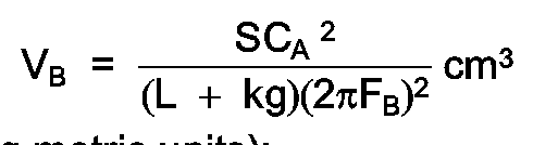
k is a Helmholtz correction factor numerically between .6 and .85;
L has a minimum dimension not exceeding the minimum dimension of g;
g is nominally initially determined by assuming that the transverse dimension g of the passageway is uniform along its width and is related to D in accordance with the formula:
g = .01072D + .1143 within the tolerance
range of +.050 cm. and -.025 cm.; and
FB equals K/D Hz, where K has a numerical value between 43,000 and 51,000.


IHP is Indicated Horsepower;
N is a constant to provide a useful range of numerical values for RQI;
ISFC is Indicated Specific Fuel Consumption of the engine, in pounds per hour per horsepower;
UHC typically is unburned hydrocarbons in parts per million hexane;
CO is carbon monoxide expressed as a volume percentage; the total air to fuel ratio required to establish maximum RQI at each engine speed/range being previously determined experimentally for the engine in accordance with standard engine mapping techniques.

k is a Helmholtz correction factor numerically between .6 and .85;
L has a minimum dimension not exceeding the minimum dimension of g;
g is nominally initially determined by assuming the passageway is uniform across its width and is related to D in accordance with the formula:
g = .01072D + .1143 within the tolerance range of +.050 cm. and -.025 cm.; and
FB = K/D Hz where K has a numerical value between 43000 and 51000.

Applications Claiming Priority (2)
| Application Number | Priority Date | Filing Date | Title |
|---|---|---|---|
| US06/880,293 US4788942A (en) | 1986-06-30 | 1986-06-30 | Internal combustion engine using dynamic resonating air chamber |
| US880293 | 1986-06-30 |
Publications (3)
| Publication Number | Publication Date |
|---|---|
| EP0271568A1 EP0271568A1 (en) | 1988-06-22 |
| EP0271568A4 EP0271568A4 (en) | 1989-10-24 |
| EP0271568B1 true EP0271568B1 (en) | 1992-01-29 |
Family
ID=25375975
Family Applications (1)
| Application Number | Title | Priority Date | Filing Date |
|---|---|---|---|
| EP87904586A Expired - Lifetime EP0271568B1 (en) | 1986-06-30 | 1987-06-23 | Internal combustion engine using dynamic resonating air chamber |
Country Status (10)
| Country | Link |
|---|---|
| US (1) | US4788942A (en) |
| EP (1) | EP0271568B1 (en) |
| JP (1) | JP2674769B2 (en) |
| KR (1) | KR950006872B1 (en) |
| AU (1) | AU596442B2 (en) |
| BR (1) | BR8707369A (en) |
| CA (1) | CA1316421C (en) |
| DE (1) | DE3776522D1 (en) |
| IN (1) | IN167102B (en) |
| WO (1) | WO1988000280A1 (en) |
Families Citing this family (58)
| Publication number | Priority date | Publication date | Assignee | Title |
|---|---|---|---|---|
| US4898135A (en) * | 1989-02-16 | 1990-02-06 | Sonex Research, Inc. | Piston and process for achieving controlled ignition and combustion of hydrocarbon fuels in internal combustion engines by generation and management of fuel radical species |
| US5065715A (en) * | 1990-02-07 | 1991-11-19 | The University Of British Columbia | Squish jet combustion chamber |
| US5076229A (en) * | 1990-10-04 | 1991-12-31 | Stanley Russel S | Internal combustion engines and method of operting an internal combustion engine using staged combustion |
| US5307773A (en) * | 1991-10-11 | 1994-05-03 | Yamaha Hatsudoki Kabushiki Kaisha | Squish structure for spark ignition engine |
| JPH0674048A (en) * | 1992-05-08 | 1994-03-15 | Royal Pootoreeto:Kk | Internal combustion engine having improved antiknock property |
| US5322042A (en) * | 1992-06-17 | 1994-06-21 | Sonex Research, Inc. | Combustion chamber for internal combustion engine and process of combustion using fuel radical species |
| US5873341A (en) * | 1993-10-29 | 1999-02-23 | Autosales, Incorporated | High performance head assembly for an internal combustion engine |
| AU695316B2 (en) * | 1994-09-29 | 1998-08-13 | Sonex Research Inc. | Charge conditioning system for enabling cold starting and running of spark-ignited, diesel fueled piston engines |
| US5692468A (en) * | 1995-07-25 | 1997-12-02 | Outboard Marine Corporation | Fuel-injected internal combustion engine with improved combustion |
| EP0834006A4 (en) * | 1996-03-19 | 1999-04-28 | Outboard Marine Corp | Two-stroke engine piston bowl configurations |
| DE19713030C2 (en) * | 1996-04-01 | 2000-02-24 | Avl List Gmbh | Four-stroke internal combustion engine with spark ignition |
| AT1562U1 (en) * | 1996-08-30 | 1997-07-25 | Avl Verbrennungskraft Messtech | FOUR-STROKE INTERNAL COMBUSTION ENGINE |
| US6085717A (en) * | 1996-08-28 | 2000-07-11 | Mitsubishi Jidosha Kogyo Kabushiki Kaisha | Fuel control device for cylinder injection type internal combustion engine |
| DE19643886C2 (en) * | 1996-10-30 | 2002-10-17 | Ficht Gmbh & Co Kg | Method for operating an internal combustion engine |
| AT2331U1 (en) * | 1997-05-28 | 1998-08-25 | Avl List Gmbh | FOUR-STROKE INTERNAL COMBUSTION ENGINE WITH IGNITION AND DIRECT INJECTION |
| US5941207A (en) * | 1997-09-08 | 1999-08-24 | Ford Global Technologies, Inc. | Direct injection spark ignition engine |
| US5970945A (en) | 1998-02-11 | 1999-10-26 | Outboard Marine Corporation | Barrier divided combustion chamber for fuel injection two-stroke engine |
| US6386175B2 (en) | 1999-03-05 | 2002-05-14 | Ford Global Technologies, Inc. | Fuel injection |
| US6357427B1 (en) * | 1999-03-15 | 2002-03-19 | Aerosance, Inc. | System and method for ignition spark energy optimization |
| US6435159B1 (en) | 2000-05-10 | 2002-08-20 | Bombardier Motor Corporation Of America | Fuel injected internal combustion engine with reduced squish factor |
| US6478006B1 (en) * | 2000-07-04 | 2002-11-12 | Lars G. Hedelin | Working cycle for a heat engine, especially an internal combustion engine, and an internal combustion engine |
| US6708666B2 (en) * | 2001-10-10 | 2004-03-23 | Southwest Research Institute | Multi-zone combustion chamber for combustion rate shaping and emissions control in premixed-charge combustion engines |
| US6936366B2 (en) * | 2002-04-03 | 2005-08-30 | Hewlett-Packard Development Company, L.P. | Single chamber solid oxide fuel cell architecture for high temperature operation |
| FR2894614B1 (en) * | 2005-12-08 | 2008-02-29 | Renault Sas | INTERNAL COMBUSTION ENGINE COMPRISING A PISTON COMPRISING A COMPLEX GEOMETRY BOSS |
| US7690478B2 (en) * | 2006-09-15 | 2010-04-06 | Visteon Global Technologies, Inc. | Continuously variable tuned resonator |
| US8176896B2 (en) * | 2008-10-08 | 2012-05-15 | GM Global Technology Operations LLC | Target wheel position detection systems |
| US8291881B2 (en) * | 2009-12-22 | 2012-10-23 | Perkins Engine Company Limited | Piston for internal combustion engine |
| US9845752B2 (en) | 2010-09-29 | 2017-12-19 | GM Global Technology Operations LLC | Systems and methods for determining crankshaft position based indicated mean effective pressure (IMEP) |
| US8612124B2 (en) | 2011-02-10 | 2013-12-17 | GM Global Technology Operations LLC | Variable valve lift mechanism fault detection systems and methods |
| US9127604B2 (en) | 2011-08-23 | 2015-09-08 | Richard Stephen Davis | Control system and method for preventing stochastic pre-ignition in an engine |
| US9097196B2 (en) | 2011-08-31 | 2015-08-04 | GM Global Technology Operations LLC | Stochastic pre-ignition detection systems and methods |
| KR20130065438A (en) * | 2011-12-09 | 2013-06-19 | 현대자동차주식회사 | Two cylinder engine |
| US8776737B2 (en) | 2012-01-06 | 2014-07-15 | GM Global Technology Operations LLC | Spark ignition to homogenous charge compression ignition transition control systems and methods |
| JP2014020238A (en) * | 2012-07-13 | 2014-02-03 | Isuzu Motors Ltd | Piston cylinder structure |
| US9133775B2 (en) | 2012-08-21 | 2015-09-15 | Brian E. Betz | Valvetrain fault indication systems and methods using engine misfire |
| US9121362B2 (en) | 2012-08-21 | 2015-09-01 | Brian E. Betz | Valvetrain fault indication systems and methods using knock sensing |
| US9567939B2 (en) | 2013-01-28 | 2017-02-14 | Sonex Research, Inc. | Thermally stratified regenerative combustion chamber |
| US9567896B2 (en) | 2013-01-28 | 2017-02-14 | Sonex Research, Inc. | Method for modifying combustion chamber in a reciprocating piston internal combustion engine and resulting engine |
| US8973429B2 (en) | 2013-02-25 | 2015-03-10 | GM Global Technology Operations LLC | System and method for detecting stochastic pre-ignition |
| US9822977B1 (en) * | 2014-02-04 | 2017-11-21 | Florida Turbine Technologies, Inc. | Advanced lean burn injector igniter system |
| US9933319B2 (en) * | 2015-04-13 | 2018-04-03 | Invensense, Inc. | Acoustic ambient temperature and humidity sensing |
| US10724424B2 (en) * | 2015-05-15 | 2020-07-28 | Cummins Inc. | Power cylinder apparatus for reducing unburnt hydrocarbon emissions |
| US10753308B2 (en) | 2017-03-30 | 2020-08-25 | Quest Engines, LLC | Internal combustion engine |
| US10526953B2 (en) | 2017-03-30 | 2020-01-07 | Quest Engines, LLC | Internal combustion engine |
| US10465629B2 (en) | 2017-03-30 | 2019-11-05 | Quest Engines, LLC | Internal combustion engine having piston with deflector channels and complementary cylinder head |
| US10989138B2 (en) | 2017-03-30 | 2021-04-27 | Quest Engines, LLC | Internal combustion engine |
| US10590813B2 (en) | 2017-03-30 | 2020-03-17 | Quest Engines, LLC | Internal combustion engine |
| US10598285B2 (en) | 2017-03-30 | 2020-03-24 | Quest Engines, LLC | Piston sealing system |
| US11041456B2 (en) | 2017-03-30 | 2021-06-22 | Quest Engines, LLC | Internal combustion engine |
| US10590834B2 (en) | 2017-03-30 | 2020-03-17 | Quest Engines, LLC | Internal combustion engine |
| WO2018201045A1 (en) | 2017-04-28 | 2018-11-01 | Quest Engines, LLC | A variable volume chamber device |
| WO2018204684A1 (en) | 2017-05-04 | 2018-11-08 | Quest Engines, LLC | Variable volume chamber for interaction with a fluid |
| WO2019050511A1 (en) * | 2017-09-06 | 2019-03-14 | Florida Turbine Technologies, Inc. | Advanced lean burn injector igniter system |
| US10808866B2 (en) | 2017-09-29 | 2020-10-20 | Quest Engines, LLC | Apparatus and methods for controlling the movement of matter |
| US10753267B2 (en) | 2018-01-26 | 2020-08-25 | Quest Engines, LLC | Method and apparatus for producing stratified streams |
| WO2019147797A2 (en) | 2018-01-26 | 2019-08-01 | Quest Engines, LLC | Audio source waveguide |
| US10865735B1 (en) | 2018-03-03 | 2020-12-15 | Steven H. Marquardt | Power piston |
| US11421609B2 (en) | 2020-03-29 | 2022-08-23 | Mark Andrew Patterson | System and process for controlled chemical ignition of internal combustion engines |
Family Cites Families (21)
| Publication number | Priority date | Publication date | Assignee | Title |
|---|---|---|---|---|
| AT95052B (en) * | 1920-12-22 | 1923-11-26 | Eugene Henri Tartrais | Combustion chamber for internal combustion engines. |
| DE412194C (en) * | 1923-03-08 | 1925-04-15 | Maximillian Orville Trudeau | Internal combustion engine with annular auxiliary combustion chamber |
| US1668471A (en) * | 1923-06-11 | 1928-05-01 | Gen Motors Res Corp | Internal-combustion engine |
| US2991766A (en) * | 1960-03-04 | 1961-07-11 | Gen Motors Corp | Air injection system for an internal combustion engine |
| US3283751A (en) * | 1963-06-28 | 1966-11-08 | Inst Khim Fysiki | Internal combustion engine with jet ignition of a non-uniformly distributed working mixture from a precombustion chamber cut-off by the piston |
| US3976038A (en) * | 1972-03-24 | 1976-08-24 | Gunter Stahl | Reciprocating stratified charge internal combustion engine and mixture formation process |
| JPS49125710A (en) * | 1973-04-09 | 1974-12-02 | ||
| JPS5650099B2 (en) * | 1973-05-04 | 1981-11-26 | ||
| US4060059A (en) * | 1973-12-07 | 1977-11-29 | Blaser Engine, Ltd. | Internal combustion engine |
| DE2502931A1 (en) * | 1974-01-25 | 1975-07-31 | Siak Hoo Ong | Rotary piston engine of epitrochoid design - fuel injection and combustion occurs in two stages |
| FR2313558A1 (en) * | 1975-06-04 | 1976-12-31 | Thery Georges | ALTERNATIVE ENGINE WITH CONTROL IGNITION AND IMPROVED COMBUSTION |
| JPS5277906A (en) * | 1975-12-24 | 1977-06-30 | Toyota Motor Corp | Reciprocating internal combustion engine |
| US4067301A (en) * | 1976-02-18 | 1978-01-10 | Le Moteur Moderne | Two-stroke engine |
| GB1591124A (en) * | 1976-10-19 | 1981-06-17 | Blaser Richard Florencio | Method and apparatus for control of pressure in internal combustion engines |
| SU956828A1 (en) * | 1977-12-01 | 1982-09-07 | Волжское объединение по производству легковых автомобилей "АвтоВАЗ" | I.c.engine |
| US4465033A (en) * | 1978-10-25 | 1984-08-14 | Blaser Richard Florencio | Energy conversion cycle for internal combustion engine and apparatus for carrying out the cycle |
| US4370959A (en) * | 1980-05-30 | 1983-02-01 | Avco Corporation | Two stroke cycle engine with sustained power stroke |
| FR2498683B1 (en) * | 1981-01-23 | 1986-07-11 | Thery Georges | COMBUSTION CHAMBER OF AN INTERNAL COMBUSTION ENGINE PROMOTING ROTARY TURBULENCE OF COMBUSTION PRODUCTS |
| JPS59530A (en) * | 1982-06-22 | 1984-01-05 | Teruhiko Matsuo | Injection combustion chamber due to auxiliary cmbustion in internal-combustion engine |
| US4485779A (en) * | 1982-12-20 | 1984-12-04 | Spurk Joseph H | Internal combustion piston engine including a cylinder having a main combustion chamber and at least one secondary combustion chamber |
| US4592318A (en) * | 1983-09-23 | 1986-06-03 | Sonex Research Inc. | Internal combustion piston engine using air chamber in piston driven in resonance with combustion wave frequency |
-
1986
- 1986-06-30 US US06/880,293 patent/US4788942A/en not_active Expired - Fee Related
-
1987
- 1987-06-23 DE DE8787904586T patent/DE3776522D1/en not_active Expired - Fee Related
- 1987-06-23 JP JP62504265A patent/JP2674769B2/en not_active Expired - Lifetime
- 1987-06-23 KR KR1019880700222A patent/KR950006872B1/en not_active Expired - Fee Related
- 1987-06-23 EP EP87904586A patent/EP0271568B1/en not_active Expired - Lifetime
- 1987-06-23 AU AU76952/87A patent/AU596442B2/en not_active Ceased
- 1987-06-23 BR BR8707369A patent/BR8707369A/en not_active IP Right Cessation
- 1987-06-23 WO PCT/US1987/001436 patent/WO1988000280A1/en not_active Ceased
- 1987-06-29 CA CA000540855A patent/CA1316421C/en not_active Expired - Fee Related
- 1987-07-01 IN IN507/CAL/87A patent/IN167102B/en unknown
Also Published As
| Publication number | Publication date |
|---|---|
| CA1316421C (en) | 1993-04-20 |
| JPH01500769A (en) | 1989-03-16 |
| EP0271568A4 (en) | 1989-10-24 |
| EP0271568A1 (en) | 1988-06-22 |
| KR880701318A (en) | 1988-07-26 |
| KR950006872B1 (en) | 1995-06-23 |
| BR8707369A (en) | 1988-09-13 |
| IN167102B (en) | 1990-09-01 |
| JP2674769B2 (en) | 1997-11-12 |
| US4788942A (en) | 1988-12-06 |
| DE3776522D1 (en) | 1992-03-12 |
| WO1988000280A1 (en) | 1988-01-14 |
| AU7695287A (en) | 1988-01-29 |
| AU596442B2 (en) | 1990-05-03 |
Similar Documents
| Publication | Publication Date | Title |
|---|---|---|
| US4788942A (en) | Internal combustion engine using dynamic resonating air chamber | |
| US4592318A (en) | Internal combustion piston engine using air chamber in piston driven in resonance with combustion wave frequency | |
| US4969425A (en) | Piston with a resonant cavity | |
| US5322042A (en) | Combustion chamber for internal combustion engine and process of combustion using fuel radical species | |
| EP0156894B1 (en) | Combustion process for i.c. engine using a resonating air chamber in a reciprocating piston to induce closed organ pipe resonance in the combustion chamber | |
| CA1133337A (en) | Method and apparatus for control of pressure in internal combustion engines | |
| US4221198A (en) | Internal combustion engine with sustained power stroke | |
| AU577548B2 (en) | Variable compression ratio engine | |
| AU575081B2 (en) | Process for carrying out radical enhanced combustion in i.c. engine | |
| AU565572B2 (en) | Piston for i.c. engine | |
| SU781375A1 (en) | Method of carrying out operation process for precombustion-chamber-type i.c. engine |
Legal Events
| Date | Code | Title | Description |
|---|---|---|---|
| PUAI | Public reference made under article 153(3) epc to a published international application that has entered the european phase |
Free format text: ORIGINAL CODE: 0009012 |
|
| 17P | Request for examination filed |
Effective date: 19880307 |
|
| AK | Designated contracting states |
Kind code of ref document: A1 Designated state(s): DE FR GB IT SE |
|
| A4 | Supplementary search report drawn up and despatched |
Effective date: 19891024 |
|
| 17Q | First examination report despatched |
Effective date: 19900425 |
|
| GRAA | (expected) grant |
Free format text: ORIGINAL CODE: 0009210 |
|
| AK | Designated contracting states |
Kind code of ref document: B1 Designated state(s): DE FR GB IT SE |
|
| REF | Corresponds to: |
Ref document number: 3776522 Country of ref document: DE Date of ref document: 19920312 |
|
| ITF | It: translation for a ep patent filed | ||
| ET | Fr: translation filed | ||
| PLBE | No opposition filed within time limit |
Free format text: ORIGINAL CODE: 0009261 |
|
| STAA | Information on the status of an ep patent application or granted ep patent |
Free format text: STATUS: NO OPPOSITION FILED WITHIN TIME LIMIT |
|
| 26N | No opposition filed | ||
| PGFP | Annual fee paid to national office [announced via postgrant information from national office to epo] |
Ref country code: SE Payment date: 19930526 Year of fee payment: 7 |
|
| PG25 | Lapsed in a contracting state [announced via postgrant information from national office to epo] |
Ref country code: SE Effective date: 19940624 |
|
| EUG | Se: european patent has lapsed |
Ref document number: 87904586.2 Effective date: 19950110 |
|
| EUG | Se: european patent has lapsed |
Ref document number: 87904586.2 |
|
| PGFP | Annual fee paid to national office [announced via postgrant information from national office to epo] |
Ref country code: GB Payment date: 19990504 Year of fee payment: 13 |
|
| PGFP | Annual fee paid to national office [announced via postgrant information from national office to epo] |
Ref country code: FR Payment date: 19990602 Year of fee payment: 13 |
|
| PGFP | Annual fee paid to national office [announced via postgrant information from national office to epo] |
Ref country code: DE Payment date: 19990624 Year of fee payment: 13 |
|
| PG25 | Lapsed in a contracting state [announced via postgrant information from national office to epo] |
Ref country code: GB Free format text: LAPSE BECAUSE OF NON-PAYMENT OF DUE FEES Effective date: 20000623 |
|
| GBPC | Gb: european patent ceased through non-payment of renewal fee |
Effective date: 20000623 |
|
| PG25 | Lapsed in a contracting state [announced via postgrant information from national office to epo] |
Ref country code: FR Free format text: LAPSE BECAUSE OF NON-PAYMENT OF DUE FEES Effective date: 20010228 |
|
| REG | Reference to a national code |
Ref country code: FR Ref legal event code: ST |
|
| PG25 | Lapsed in a contracting state [announced via postgrant information from national office to epo] |
Ref country code: DE Free format text: LAPSE BECAUSE OF NON-PAYMENT OF DUE FEES Effective date: 20010403 |
|
| PG25 | Lapsed in a contracting state [announced via postgrant information from national office to epo] |
Ref country code: IT Free format text: LAPSE BECAUSE OF NON-PAYMENT OF DUE FEES;WARNING: LAPSES OF ITALIAN PATENTS WITH EFFECTIVE DATE BEFORE 2007 MAY HAVE OCCURRED AT ANY TIME BEFORE 2007. THE CORRECT EFFECTIVE DATE MAY BE DIFFERENT FROM THE ONE RECORDED. Effective date: 20050623 |