EP0271429B1 - Heat pump charging - Google Patents
Heat pump charging Download PDFInfo
- Publication number
- EP0271429B1 EP0271429B1 EP87630257A EP87630257A EP0271429B1 EP 0271429 B1 EP0271429 B1 EP 0271429B1 EP 87630257 A EP87630257 A EP 87630257A EP 87630257 A EP87630257 A EP 87630257A EP 0271429 B1 EP0271429 B1 EP 0271429B1
- Authority
- EP
- European Patent Office
- Prior art keywords
- heat pump
- refrigerant
- charging
- compressor
- pump system
- Prior art date
- Legal status (The legal status is an assumption and is not a legal conclusion. Google has not performed a legal analysis and makes no representation as to the accuracy of the status listed.)
- Expired - Lifetime
Links
- 239000003507 refrigerant Substances 0.000 claims description 38
- 238000000034 method Methods 0.000 claims description 7
- 238000012544 monitoring process Methods 0.000 claims description 4
- 230000003467 diminishing effect Effects 0.000 claims 1
- 238000001816 cooling Methods 0.000 description 9
- 238000010438 heat treatment Methods 0.000 description 4
- 239000007788 liquid Substances 0.000 description 2
- 230000002441 reversible effect Effects 0.000 description 2
- 238000012937 correction Methods 0.000 description 1
- 239000012530 fluid Substances 0.000 description 1
- 239000007791 liquid phase Substances 0.000 description 1
Images


Classifications
-
- F—MECHANICAL ENGINEERING; LIGHTING; HEATING; WEAPONS; BLASTING
- F25—REFRIGERATION OR COOLING; COMBINED HEATING AND REFRIGERATION SYSTEMS; HEAT PUMP SYSTEMS; MANUFACTURE OR STORAGE OF ICE; LIQUEFACTION SOLIDIFICATION OF GASES
- F25B—REFRIGERATION MACHINES, PLANTS OR SYSTEMS; COMBINED HEATING AND REFRIGERATION SYSTEMS; HEAT PUMP SYSTEMS
- F25B45/00—Arrangements for charging or discharging refrigerant
-
- F—MECHANICAL ENGINEERING; LIGHTING; HEATING; WEAPONS; BLASTING
- F25—REFRIGERATION OR COOLING; COMBINED HEATING AND REFRIGERATION SYSTEMS; HEAT PUMP SYSTEMS; MANUFACTURE OR STORAGE OF ICE; LIQUEFACTION SOLIDIFICATION OF GASES
- F25B—REFRIGERATION MACHINES, PLANTS OR SYSTEMS; COMBINED HEATING AND REFRIGERATION SYSTEMS; HEAT PUMP SYSTEMS
- F25B2345/00—Details for charging or discharging refrigerants; Service stations therefor
- F25B2345/001—Charging refrigerant to a cycle
-
- F—MECHANICAL ENGINEERING; LIGHTING; HEATING; WEAPONS; BLASTING
- F25—REFRIGERATION OR COOLING; COMBINED HEATING AND REFRIGERATION SYSTEMS; HEAT PUMP SYSTEMS; MANUFACTURE OR STORAGE OF ICE; LIQUEFACTION SOLIDIFICATION OF GASES
- F25B—REFRIGERATION MACHINES, PLANTS OR SYSTEMS; COMBINED HEATING AND REFRIGERATION SYSTEMS; HEAT PUMP SYSTEMS
- F25B2345/00—Details for charging or discharging refrigerants; Service stations therefor
- F25B2345/003—Control issues for charging or collecting refrigerant to or from a cycle
-
- F—MECHANICAL ENGINEERING; LIGHTING; HEATING; WEAPONS; BLASTING
- F25—REFRIGERATION OR COOLING; COMBINED HEATING AND REFRIGERATION SYSTEMS; HEAT PUMP SYSTEMS; MANUFACTURE OR STORAGE OF ICE; LIQUEFACTION SOLIDIFICATION OF GASES
- F25B—REFRIGERATION MACHINES, PLANTS OR SYSTEMS; COMBINED HEATING AND REFRIGERATION SYSTEMS; HEAT PUMP SYSTEMS
- F25B2345/00—Details for charging or discharging refrigerants; Service stations therefor
- F25B2345/006—Details for charging or discharging refrigerants; Service stations therefor characterised by charging or discharging valves
Definitions
- the invention herein is directed toward the field of heat pump systems and particularly toward the field of charging techniques for the closed refrigerant loop of a heat pump system, especially one active in the cooling mode of operation.
- Heat pump systems of many kinds are well known.
- One kind in common use employs indoor and outdoor coils connected by reversible expansion valves which operate in one direction during the heating mode of the heat pump system, and in the other direction during the cooling mode of operation.
- the heat pump systems typically additionally include a compressor to drive refrigerant through the respective coils one way or the other. Often the compressor itself is not reversible, so a four-way valve is employed to switch the compressor output from one coil to the other.
- a typical system further includes an accumulator at the input of the compressor, which generally acts to collect excess liquid refrigerant from refrigerant gas just before entry to the compressor.
- the compressor acts upon refrigerant gas.
- the refrigerant At the output of one of the coils, i.e. the condenser coil, the refrigerant will be in liquid phase because of the loss of heat from the refrigerant in the condenser.
- the outdoor coil acts as the condensing coil.
- liquid refrigerant may be injected into the compressor possibly causing it to fail. Additionally, complicated temperature and pressure corrections may have to be made as a result of overcharging, which require specialized equipment and consume inordinate amounts of time and other resources to perform.
- US-A 4 484 452 discloses a method of charging a heat pump system according to the preamble of the independent claims.
- the object of the invention is to provide a method of charging a heat pump system which avoids overcharging thereof.
- charging of the heat pump system with refrigerant during the cooling mode is accomplished by performing the following steps. These include turning on both the indoor and the outdoor fans of the heat pump system, connecting an input refrigerant container which is brought to the site by service personnel, to a Schrader valve of the heat pump system, then introducing sufficient amounts of refrigerant to operate the compressor, checking the outdoor and indoor ambient temperatures, and monitoring temperature at the outlet of the indoor coil.
- the compressor driving refrigerant through the closed refrigerant loop of the heat pump system is operated at full speed. Then, if the difference between the ambient temperature at the inlet of the outdoor coil and the refrigerant temperature at the output of the outdoor coil in successive time periods does not remain greater than a selected difference threshold such as for example two (2) degrees Fahrenheit, charging is discontinued. If the outdoor coil inlet ambient temperature drops below the indicated ambient threshold, the compressor is operated at a lower selected level, and charging of the refrigerant loop continues until the temperature difference between outdoor ambient and coil output drops below a scheduled level.
- a predetermined ambient threshold level such as for example 60 ° Fahrenheit
- compressor 101 receives refrigerant from accumulator 102, which collects varying amounts of refrigerant, depending upon whether the heat pump system is operating in the cooling or heating mode of operation.
- New refrigerant is injected through charging solenoid valve 103 and a Schrader valve 110 for example which in turn connects to a refrigerant supply tank 103' which is brought to the scene of operations by service personnel.
- Four-way valve 104 permits the heat pump arrangement 13 to be operated in heating or cooling modes by directing refrigerant either to indoor or outdoor coil, respectively 105 and 106.
- refrigerant is transported to the valve 104 from indoor coil 105 and passes toward accumulator 102.
- refrigerant passes from outdoor coil 106 toward valve 104 and then toward accumulator 102.
- expansion devices 107 and 107', a controller 108, indoor and outdoor temperature sensors 109(3), and 109(2) effective respectively for sensing the refrigerant temperature at the the indoor coil inlet and at the outdoor coil inlet 105 are additionally included in heat pump system 13.
- FIG. 2 shows in partial cross section details of the charging solenoid valve 103 and a portion of the tubing 224 between accumulator 102 and four-way valve 104.
- valve 103 includes solenoid 103' for controlling the flow from Schrader valve 110 through a narrowed passage 333 and into suction tube 224 during charging operation performed according to the scheme set forth in the flow chart of Figure 3.
- Figure 3 shows the steps involved in performing operation in accordance with the invention herein.
- block 401 indicates the first step of operation, namely turning on the indoor and outdoor fans respectively 105' and 106' to enable heat transfer with air through respective coils 105 and 106.
- Controller 108 (which is preferably a microprocessor of suitable type) is effective for storing the respective values of indoor and outdoor ambient temperatures which have been checked.
- a selected bottle tank or container 103' filled with refrigerant and brought by service personnel is attached to the Schrader valve 10, according to block 420, and a predetermined amount of refrigerant is introduced into system 13, which is sufficient to permit safe compressor operation, as suggested at block 431.
- compressor 101 begins operation, the heat pump system 13 is started and a predetermined period of time is marked by controller 108, permitting conditions in system 13 to stabilize. Concurrently therewith, the inlet temperature at outlet coil 106 is monitored with thermistor 109(2) and a signal indicative thereof is sent along line 109'(2) to controller 108. The system 13 operates with compressor 101 at full speed, as suggested by block 440, if the outdoor ambient temperature exceeds a predetermined threshold such as 60 ° F for example. On the other hand, if the outdoor ambient temperature is below 60°F, or another selected value, threshold or set point, compressor operation is set to less than full speed as suggested in block 440'. Next, the indoor coil inlet and suction temperatures respectively at sensors 109 (3) and 109(1), between accumulator 102 and are monitored as suggested at block 451. Further, the difference between these values is determined, once or twice at least.
- a predetermined threshold such as 60 ° F for example.
- charging events are conducted and continue.Charging can be considered to involve repeated charging pulses or events, each producing a discrete quantity of charging refrigerant.
- the monitored temperature difference falls below a predetermined functional value represented by the curve of Figure 4 for a given ambient operating temperature (all these being below 60°F)
- charging stops as well.
- the chart of Figure 4 suggests a schedule of acceptable temperature differences at the input and output of outdoor coil 106 as a function of outdoor ambient temperature.
- the temperature difference is greater than a predetermined functional value, charging continues.
- Figure 5 shows the case in which the outdoor (OD) ambient temperature is greater than sixty (60) degrees, as represented by block 412.
- block 440 urges starting the compressor 101 and operating it at full speed.
- block 451 extablishes the subsequent step of monitoring respective indoor inlet and suction temperatures, respectively "Ti " and "T 2 " at respective sensors 109(3) and 109(1).
- the difference between T 2 and Ti is taken, as suggested at block 460 and then charging is conducted as per block 465.
- the procedure of block 451 is repeated and a new temperature difference delta T; is established as shown.
- a difference of differences is taken to determine whether charging continues or stops.
- Figure 6 shows at block 412 and thereafter the charging procedure if the outdoor (OD) ambient temperature is between thirty (30) and sixty (60) degrees, that is less than sixty (60) and greater than thirty (30) degrees, in which case per block 440', the compressor is run at some speed other than full speed, followed by charging as per block 465 and establishment of a temperature difference as per block 451'. Charging continues, if the temperature difference remains above tabulated values, indicated for example at Figure 4. Otherwise, charging stops as indicated at oval 471
Landscapes
- Engineering & Computer Science (AREA)
- Physics & Mathematics (AREA)
- Mechanical Engineering (AREA)
- Thermal Sciences (AREA)
- General Engineering & Computer Science (AREA)
- Air Conditioning Control Device (AREA)
- Compression-Type Refrigeration Machines With Reversible Cycles (AREA)
- Structures Of Non-Positive Displacement Pumps (AREA)
Description
- The invention herein is directed toward the field of heat pump systems and particularly toward the field of charging techniques for the closed refrigerant loop of a heat pump system, especially one active in the cooling mode of operation.
- Heat pump systems of many kinds are well known. One kind in common use employs indoor and outdoor coils connected by reversible expansion valves which operate in one direction during the heating mode of the heat pump system, and in the other direction during the cooling mode of operation. The heat pump systems typically additionally include a compressor to drive refrigerant through the respective coils one way or the other. Often the compressor itself is not reversible, so a four-way valve is employed to switch the compressor output from one coil to the other. A typical system further includes an accumulator at the input of the compressor, which generally acts to collect excess liquid refrigerant from refrigerant gas just before entry to the compressor.
- As suggested, the compressor acts upon refrigerant gas. At the output of one of the coils, i.e. the condenser coil, the refrigerant will be in liquid phase because of the loss of heat from the refrigerant in the condenser. During the cooling mode of operation, the outdoor coil acts as the condensing coil.
- It is thus addressed herein how best controllably to charge heat pump systems with refrigerant fluid during servicing in particular while the heat pump is in its cooling mode. More specifically, it is desired to prevent overcharging split system variable capacity heat pumps, in which one coil is outdoors and the other is indoors, during charging operation in the cooling operational mode of the heat pump system. Overcharging typically occurs in the field during charging operation by inexperienced field personnel conducting charging operation manually.
- Once a heat pump is overcharged, liquid refrigerant may be injected into the compressor possibly causing it to fail. Additionally, complicated temperature and pressure corrections may have to be made as a result of overcharging, which require specialized equipment and consume inordinate amounts of time and other resources to perform.
- US-A 4 484 452 discloses a method of charging a heat pump system according to the preamble of the independent claims.
- The object of the invention is to provide a method of charging a heat pump system which avoids overcharging thereof.
- This object is achieved by the characterizing features of the independent claims.
- According to the invention herein, charging of the heat pump system with refrigerant during the cooling mode is accomplished by performing the following steps. These include turning on both the indoor and the outdoor fans of the heat pump system, connecting an input refrigerant container which is brought to the site by service personnel, to a Schrader valve of the heat pump system, then introducing sufficient amounts of refrigerant to operate the compressor, checking the outdoor and indoor ambient temperatures, and monitoring temperature at the outlet of the indoor coil.
- If either of the ambient temperatures exceeds a predetermined ambient threshold level, such as for example 60° Fahrenheit, the compressor driving refrigerant through the closed refrigerant loop of the heat pump system is operated at full speed. Then, if the difference between the ambient temperature at the inlet of the outdoor coil and the refrigerant temperature at the output of the outdoor coil in successive time periods does not remain greater than a selected difference threshold such as for example two (2) degrees Fahrenheit, charging is discontinued. If the outdoor coil inlet ambient temperature drops below the indicated ambient threshold, the compressor is operated at a lower selected level, and charging of the refrigerant loop continues until the temperature difference between outdoor ambient and coil output drops below a scheduled level.
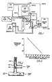
- Figure 1 shows the schematic of a preferred version of the heat pump system, in particular a split system effective for permitting operation according to the invention herein.
- Figure 2 shows a detail of a portion of the heat pump system in partial cross section, in particular showing a solenoid controlled charging valve employed during charging operation as discussed herein.
- Figure 3 is a flow chart illustrating operation according to the invention herein.
- Figure 4 is a graph of ambient temperature as a function of temperature differences between ambient inlet and refrigerant outlet sides of the outdoor coil.
- Figures 5 and 6 are additional flow charts illustrating operation of the invention according to first and second preferred versions thereof.
- Figure 1 in particular shows a heat pump arrangement or system 13 which is operable according to the invention herein. In particular, system 13 includes a compressor 101 for compressing refrigerant gas and effectively driving it through the closed loop refrigerant portion of heat pump system 13.
- More specifically, compressor 101 receives refrigerant from
accumulator 102, which collects varying amounts of refrigerant, depending upon whether the heat pump system is operating in the cooling or heating mode of operation. - New refrigerant is injected through charging
solenoid valve 103 and aSchrader valve 110 for example which in turn connects to a refrigerant supply tank 103' which is brought to the scene of operations by service personnel. - Four-
way valve 104, permits the heat pump arrangement 13 to be operated in heating or cooling modes by directing refrigerant either to indoor or outdoor coil, respectively 105 and 106. In particular, during the cooling mode, which is of particular interest herein, refrigerant is transported to thevalve 104 fromindoor coil 105 and passes towardaccumulator 102. During the heating mode, refrigerant passes fromoutdoor coil 106 towardvalve 104 and then towardaccumulator 102. - Additionally,
expansion devices 107 and 107', acontroller 108, indoor and outdoor temperature sensors 109(3), and 109(2) effective respectively for sensing the refrigerant temperature at the the indoor coil inlet and at theoutdoor coil inlet 105 are additionally included in heat pump system 13. - Figure 2 shows in partial cross section details of the charging
solenoid valve 103 and a portion of thetubing 224 betweenaccumulator 102 and four-way valve 104. As can be seen,valve 103 includes solenoid 103' for controlling the flow fromSchrader valve 110 through a narrowedpassage 333 and intosuction tube 224 during charging operation performed according to the scheme set forth in the flow chart of Figure 3. - As suggested, Figure 3 shows the steps involved in performing operation in accordance with the invention herein. In particular,
block 401 indicates the first step of operation, namely turning on the indoor and outdoor fans respectively 105' and 106' to enable heat transfer with air throughrespective coils - Next, both indoor and outdoor coil refrigerant temperatures are checked, i.e. detected and signalled electrically to controller 108, by respective thermistor elements 109(3) and 109(2) respectively at indoor and
outdoor coils block 410. Controller 108 (which is preferably a microprocessor of suitable type) is effective for storing the respective values of indoor and outdoor ambient temperatures which have been checked. - Concurrently, or at least temporally proximate thereto, a selected bottle tank or container 103' filled with refrigerant and brought by service personnel is attached to the
Schrader valve 10, according toblock 420, and a predetermined amount of refrigerant is introduced into system 13, which is sufficient to permit safe compressor operation, as suggested atblock 431. - Once compressor 101 begins operation, the heat pump system 13 is started and a predetermined period of time is marked by
controller 108, permitting conditions in system 13 to stabilize. Concurrently therewith, the inlet temperature atoutlet coil 106 is monitored with thermistor 109(2) and a signal indicative thereof is sent along line 109'(2) to controller 108. The system 13 operates with compressor 101 at full speed, as suggested byblock 440, if the outdoor ambient temperature exceeds a predetermined threshold such as 60°F for example. On the other hand, if the outdoor ambient temperature is below 60°F, or another selected value, threshold or set point, compressor operation is set to less than full speed as suggested in block 440'. Next, the indoor coil inlet and suction temperatures respectively at sensors 109 (3) and 109(1), betweenaccumulator 102 and are monitored as suggested atblock 451. Further, the difference between these values is determined, once or twice at least. - In the event that the monitored temperature differences diminish by more than a predetermined amount in successive microprocessor cycles of operation, as by 3°F for example as suggested at block 460', according to one version of the invention (e.g. in the case of ambient temperature exceeding 60°F for another selected value), charging events are conducted and continue.Charging can be considered to involve repeated charging pulses or events, each producing a discrete quantity of charging refrigerant.
- According to another version of the invention, if, for instance, the monitored temperature difference falls below a predetermined functional value represented by the curve of Figure 4 for a given ambient operating temperature (all these being below 60°F), charging stops as well. Thus, the chart of Figure 4 suggests a schedule of acceptable temperature differences at the input and output of
outdoor coil 106 as a function of outdoor ambient temperature. However, as suggested atblock 460 of Figure 3, if the temperature difference is greater than a predetermined functional value, charging continues. - To further illustrate these two versions of the invention, see Figures 5 and 6. In particular, Figure 5 shows the case in which the outdoor (OD) ambient temperature is greater than sixty (60) degrees, as represented by
block 412. As already noted,block 440 urges starting the compressor 101 and operating it at full speed. Next,block 451 extablishes the subsequent step of monitoring respective indoor inlet and suction temperatures, respectively "Ti " and "T2" at respective sensors 109(3) and 109(1). Then, the difference between T2 and Ti is taken, as suggested atblock 460 and then charging is conducted as perblock 465. Thereafter, the procedure ofblock 451 is repeated and a new temperature difference delta T; is established as shown. Then, as per block 460', a difference of differences is taken to determine whether charging continues or stops. - Figure 6 shows at
block 412 and thereafter the charging procedure if the outdoor (OD) ambient temperature is between thirty (30) and sixty (60) degrees, that is less than sixty (60) and greater than thirty (30) degrees, in which case per block 440', the compressor is run at some speed other than full speed, followed by charging as perblock 465 and establishment of a temperature difference as per block 451'. Charging continues, if the temperature difference remains above tabulated values, indicated for example at Figure 4. Otherwise, charging stops as indicated atoval 471
Claims (2)
Applications Claiming Priority (2)
| Application Number | Priority Date | Filing Date | Title |
|---|---|---|---|
| US939825 | 1986-12-09 | ||
| US06/939,825 US4796436A (en) | 1986-12-09 | 1986-12-09 | Heat pump charging |
Publications (2)
| Publication Number | Publication Date |
|---|---|
| EP0271429A1 EP0271429A1 (en) | 1988-06-15 |
| EP0271429B1 true EP0271429B1 (en) | 1990-05-09 |
Family
ID=25473801
Family Applications (1)
| Application Number | Title | Priority Date | Filing Date |
|---|---|---|---|
| EP87630257A Expired - Lifetime EP0271429B1 (en) | 1986-12-09 | 1987-12-01 | Heat pump charging |
Country Status (5)
| Country | Link |
|---|---|
| US (1) | US4796436A (en) |
| EP (1) | EP0271429B1 (en) |
| JP (1) | JPH0621749B2 (en) |
| KR (1) | KR910006218B1 (en) |
| ES (1) | ES2014492B3 (en) |
Families Citing this family (20)
| Publication number | Priority date | Publication date | Assignee | Title |
|---|---|---|---|---|
| US5201862A (en) * | 1989-02-13 | 1993-04-13 | General Motors Corporation | Low refrigerant charge protection method |
| JPH0743193B2 (en) * | 1990-11-30 | 1995-05-15 | サンデン株式会社 | Refrigerant overfill prevention device |
| JPH05118719A (en) * | 1991-10-15 | 1993-05-14 | Sanden Corp | Revolution control of motor-driven compressor |
| JPH09329375A (en) * | 1996-06-10 | 1997-12-22 | Sanyo Electric Co Ltd | Replenishing/filling method of non-azeorope refrigerant and device thereof |
| US6269840B1 (en) | 1996-12-10 | 2001-08-07 | American Standard International Inc. | Valve-in-valve body, vent port and method |
| JP3152187B2 (en) * | 1997-11-21 | 2001-04-03 | ダイキン工業株式会社 | Refrigeration apparatus and refrigerant charging method |
| FR2851328B1 (en) * | 2003-02-14 | 2006-02-24 | Pascal Maurice Bequet | DEVICE FOR MONITORING THE REFRIGERANT FLUID LOAD OF AN AIR CONDITIONING FACILITY |
| US7310956B2 (en) * | 2004-11-18 | 2007-12-25 | Snap-On Incorporated | Refrigerant charging by optimum performance |
| KR101340725B1 (en) * | 2006-10-17 | 2013-12-12 | 엘지전자 주식회사 | Water cooling type air conditioner |
| US9163866B2 (en) * | 2006-11-30 | 2015-10-20 | Lennox Industries Inc. | System pressure actuated charge compensator |
| ES2690822T3 (en) * | 2007-11-01 | 2018-11-22 | Mitsubishi Electric Corporation | Refrigerant filling apparatus of refrigeration and air conditioning apparatus and refrigerant filling method of refrigeration and air conditioning apparatus |
| KR101526340B1 (en) * | 2009-05-15 | 2015-06-05 | 엘지전자 주식회사 | Coolant charging device and Coolant charging method for air conditioner |
| CN102762936B (en) * | 2010-02-26 | 2015-10-21 | 罗伯特·博世有限公司 | Method for recovering refrigerant from refrigeration equipment |
| US9897365B2 (en) * | 2011-12-14 | 2018-02-20 | Lg Electronics Inc. | Refrigerator, thermosyphon, and solenoid valve and method for controlling the same |
| US9759465B2 (en) | 2011-12-27 | 2017-09-12 | Carrier Corporation | Air conditioner self-charging and charge monitoring system |
| US9777724B2 (en) | 2012-12-21 | 2017-10-03 | Trane International Inc. | System and method for controlling a system that includes variable speed compressor |
| US9638446B2 (en) * | 2014-09-03 | 2017-05-02 | Mahle International Gmbh | Method to detect low charge levels in a refrigeration circuit |
| US10281170B2 (en) * | 2016-08-16 | 2019-05-07 | Haier Us Appliance Solutions, Inc. | Sealed refrigeration system and appliance |
| US10794621B2 (en) * | 2016-11-18 | 2020-10-06 | Lg Electronics Inc. | Air conditoner and method for controlling an air conditioner |
| US12173942B2 (en) | 2021-08-26 | 2024-12-24 | Carrier Corporation | Method of operating a heat pump system |
Family Cites Families (13)
| Publication number | Priority date | Publication date | Assignee | Title |
|---|---|---|---|---|
| US2055780A (en) * | 1934-07-17 | 1936-09-29 | Baldwin Southwark Corp | Reserve refrigerant supply and apparatus |
| US3076319A (en) * | 1961-02-13 | 1963-02-05 | Phil Rich Fan Mfg Company Inc | Refrigeration charging apparatus |
| US3303663A (en) * | 1965-10-20 | 1967-02-14 | Luxaire Inc | Refrigeration system charging apparatus |
| US3400552A (en) * | 1967-02-13 | 1968-09-10 | Luxaire Inc | Electrically controlled refrigerant charging device |
| US3875755A (en) * | 1974-01-02 | 1975-04-08 | Heil Quaker Corp | Method of charging a refrigeration system and apparatus therefor |
| US3903709A (en) * | 1974-01-02 | 1975-09-09 | Heil Quaker Corp | Refrigerant charging apparatus |
| US4100306A (en) * | 1976-02-05 | 1978-07-11 | The Procter & Gamble Company | Method of making an improved instant coffee |
| CA1088183A (en) * | 1976-06-24 | 1980-10-21 | Trane Company Of Canada Limited | Refrigerant charge adjuster apparatus |
| JPS5463446A (en) * | 1977-10-28 | 1979-05-22 | Zeneraru Eakon Kk | Method of and apparatus for packing refrigerant |
| SE426620B (en) * | 1978-08-24 | 1983-01-31 | Karl Sixten Langgard | REGULATION OF THE QUANTITY OF ENERGY CONTROLLER, IN A HEAT OR COOLING DEVICE, DEPENDENT ON THE DRIVE ENGINE LOAD |
| JPS5649868A (en) * | 1979-09-28 | 1981-05-06 | Saginomiya Seisakusho Inc | Abnormality detection method of refrigerating system |
| US4484452A (en) * | 1983-06-23 | 1984-11-27 | The Trane Company | Heat pump refrigerant charge control system |
| US4523435A (en) * | 1983-12-19 | 1985-06-18 | Carrier Corporation | Method and apparatus for controlling a refrigerant expansion valve in a refrigeration system |
-
1986
- 1986-12-09 US US06/939,825 patent/US4796436A/en not_active Expired - Fee Related
-
1987
- 1987-12-01 EP EP87630257A patent/EP0271429B1/en not_active Expired - Lifetime
- 1987-12-01 ES ES87630257T patent/ES2014492B3/en not_active Expired - Lifetime
- 1987-12-09 KR KR1019870014057A patent/KR910006218B1/en not_active Expired
- 1987-12-09 JP JP62311787A patent/JPH0621749B2/en not_active Expired - Lifetime
Also Published As
| Publication number | Publication date |
|---|---|
| KR880007987A (en) | 1988-08-30 |
| EP0271429A1 (en) | 1988-06-15 |
| KR910006218B1 (en) | 1991-08-17 |
| JPH0621749B2 (en) | 1994-03-23 |
| JPS63161375A (en) | 1988-07-05 |
| US4796436A (en) | 1989-01-10 |
| ES2014492B3 (en) | 1990-07-16 |
Similar Documents
| Publication | Publication Date | Title |
|---|---|---|
| US4796436A (en) | Heat pump charging | |
| US4535598A (en) | Method and control system for verifying sensor operation in a refrigeration system | |
| US5065593A (en) | Method for controlling indoor coil freeze-up of heat pumps and air conditioners | |
| CA1298383C (en) | Adaptive defrost system with ambient condition change detector | |
| US5319943A (en) | Frost/defrost control system for heat pump | |
| KR950011376B1 (en) | Space heating and water heating control method using variable speed heat pump | |
| US6745584B2 (en) | Digital scroll condensing unit controller | |
| US6041605A (en) | Compressor protection | |
| US4850200A (en) | Refrigerating circuit device for air conditioning apparatus and control method thereof | |
| US4407138A (en) | Heat pump system defrost control system with override | |
| EP1884726B1 (en) | Method of controlling air conditioner | |
| EP0158582A2 (en) | Dual pump down cycle for protecting a compressor in a refrigeration system | |
| EP0552127B1 (en) | Automatic chiller stopping sequence | |
| CA2048249A1 (en) | Method for detecting and correcting reversing valve failures in heat pump systems having a variable speed compressor | |
| CA2131453A1 (en) | Control system for an air conditioning/refrigeration system | |
| JPH06241595A (en) | Heat pump system and control method of operation thereof | |
| US5309728A (en) | Control apparatus for multiple unit air conditioning system | |
| JPS6325458A (en) | Method and device for controlling surge of refrigeration system | |
| EP0542665B1 (en) | Automatic chiller plant balancing | |
| US6826917B1 (en) | Initial pull down control for a multiple compressor refrigeration system | |
| JPH08166174A (en) | Air conditioner | |
| CN113701371A (en) | Direct evaporation type refrigerating unit and control method thereof | |
| JP3340601B2 (en) | Refrigeration apparatus, control method thereof, and outdoor unit for refrigeration apparatus | |
| JPS6332272A (en) | Refrigerator | |
| JP3605085B2 (en) | Air conditioner |
Legal Events
| Date | Code | Title | Description |
|---|---|---|---|
| PUAI | Public reference made under article 153(3) epc to a published international application that has entered the european phase |
Free format text: ORIGINAL CODE: 0009012 |
|
| 17P | Request for examination filed |
Effective date: 19880311 |
|
| AK | Designated contracting states |
Kind code of ref document: A1 Designated state(s): ES FR GB IT |
|
| 17Q | First examination report despatched |
Effective date: 19890127 |
|
| GRAA | (expected) grant |
Free format text: ORIGINAL CODE: 0009210 |
|
| AK | Designated contracting states |
Kind code of ref document: B1 Designated state(s): ES FR GB IT |
|
| ET | Fr: translation filed | ||
| ITF | It: translation for a ep patent filed | ||
| PLBE | No opposition filed within time limit |
Free format text: ORIGINAL CODE: 0009261 |
|
| STAA | Information on the status of an ep patent application or granted ep patent |
Free format text: STATUS: NO OPPOSITION FILED WITHIN TIME LIMIT |
|
| 26N | No opposition filed | ||
| ITTA | It: last paid annual fee | ||
| PGFP | Annual fee paid to national office [announced via postgrant information from national office to epo] |
Ref country code: FR Payment date: 19951110 Year of fee payment: 9 |
|
| PGFP | Annual fee paid to national office [announced via postgrant information from national office to epo] |
Ref country code: GB Payment date: 19951121 Year of fee payment: 9 |
|
| PGFP | Annual fee paid to national office [announced via postgrant information from national office to epo] |
Ref country code: ES Payment date: 19951211 Year of fee payment: 9 |
|
| PG25 | Lapsed in a contracting state [announced via postgrant information from national office to epo] |
Ref country code: GB Effective date: 19961201 |
|
| GBPC | Gb: european patent ceased through non-payment of renewal fee |
Effective date: 19961201 |
|
| PG25 | Lapsed in a contracting state [announced via postgrant information from national office to epo] |
Ref country code: FR Effective date: 19970829 |
|
| REG | Reference to a national code |
Ref country code: FR Ref legal event code: ST |
|
| PG25 | Lapsed in a contracting state [announced via postgrant information from national office to epo] |
Ref country code: ES Free format text: LAPSE BECAUSE OF NON-PAYMENT OF DUE FEES Effective date: 19971202 |
|
| REG | Reference to a national code |
Ref country code: ES Ref legal event code: FD2A Effective date: 19980113 |
|
| PG25 | Lapsed in a contracting state [announced via postgrant information from national office to epo] |
Ref country code: IT Free format text: LAPSE BECAUSE OF NON-PAYMENT OF DUE FEES;WARNING: LAPSES OF ITALIAN PATENTS WITH EFFECTIVE DATE BEFORE 2007 MAY HAVE OCCURRED AT ANY TIME BEFORE 2007. THE CORRECT EFFECTIVE DATE MAY BE DIFFERENT FROM THE ONE RECORDED. Effective date: 20051201 |