EP0271356B1 - Gas separation and purification - Google Patents
Gas separation and purification Download PDFInfo
- Publication number
- EP0271356B1 EP0271356B1 EP87310920A EP87310920A EP0271356B1 EP 0271356 B1 EP0271356 B1 EP 0271356B1 EP 87310920 A EP87310920 A EP 87310920A EP 87310920 A EP87310920 A EP 87310920A EP 0271356 B1 EP0271356 B1 EP 0271356B1
- Authority
- EP
- European Patent Office
- Prior art keywords
- bed
- gas
- feed
- depressurizing
- components
- Prior art date
- Legal status (The legal status is an assumption and is not a legal conclusion. Google has not performed a legal analysis and makes no representation as to the accuracy of the status listed.)
- Expired - Lifetime
Links
- 238000000926 separation method Methods 0.000 title claims abstract description 24
- 238000000746 purification Methods 0.000 title description 2
- 238000001179 sorption measurement Methods 0.000 claims abstract description 41
- 238000000034 method Methods 0.000 claims abstract description 39
- 239000003463 adsorbent Substances 0.000 claims abstract description 31
- 239000000203 mixture Substances 0.000 claims abstract description 23
- 239000007789 gas Substances 0.000 claims description 106
- 239000001257 hydrogen Substances 0.000 claims description 35
- 229910052739 hydrogen Inorganic materials 0.000 claims description 35
- CURLTUGMZLYLDI-UHFFFAOYSA-N Carbon dioxide Chemical compound O=C=O CURLTUGMZLYLDI-UHFFFAOYSA-N 0.000 claims description 33
- UFHFLCQGNIYNRP-UHFFFAOYSA-N Hydrogen Chemical compound [H][H] UFHFLCQGNIYNRP-UHFFFAOYSA-N 0.000 claims description 30
- UGFAIRIUMAVXCW-UHFFFAOYSA-N Carbon monoxide Chemical compound [O+]#[C-] UGFAIRIUMAVXCW-UHFFFAOYSA-N 0.000 claims description 26
- 229910002091 carbon monoxide Inorganic materials 0.000 claims description 26
- 239000000463 material Substances 0.000 claims description 20
- 238000010926 purge Methods 0.000 claims description 20
- 229910002092 carbon dioxide Inorganic materials 0.000 claims description 17
- VNWKTOKETHGBQD-UHFFFAOYSA-N methane Chemical compound C VNWKTOKETHGBQD-UHFFFAOYSA-N 0.000 claims description 14
- OKTJSMMVPCPJKN-UHFFFAOYSA-N Carbon Chemical compound [C] OKTJSMMVPCPJKN-UHFFFAOYSA-N 0.000 claims description 8
- IJGRMHOSHXDMSA-UHFFFAOYSA-N Atomic nitrogen Chemical compound N#N IJGRMHOSHXDMSA-UHFFFAOYSA-N 0.000 claims description 6
- 239000002808 molecular sieve Substances 0.000 claims description 4
- URGAHOPLAPQHLN-UHFFFAOYSA-N sodium aluminosilicate Chemical compound [Na+].[Al+3].[O-][Si]([O-])=O.[O-][Si]([O-])=O URGAHOPLAPQHLN-UHFFFAOYSA-N 0.000 claims description 4
- 229910052757 nitrogen Inorganic materials 0.000 claims description 3
- VYPSYNLAJGMNEJ-UHFFFAOYSA-N Silicium dioxide Chemical compound O=[Si]=O VYPSYNLAJGMNEJ-UHFFFAOYSA-N 0.000 claims description 2
- PNEYBMLMFCGWSK-UHFFFAOYSA-N aluminium oxide Inorganic materials [O-2].[O-2].[O-2].[Al+3].[Al+3] PNEYBMLMFCGWSK-UHFFFAOYSA-N 0.000 claims description 2
- 239000001569 carbon dioxide Substances 0.000 claims description 2
- 239000000741 silica gel Substances 0.000 claims description 2
- 229910002027 silica gel Inorganic materials 0.000 claims description 2
- 239000000047 product Substances 0.000 description 50
- 238000006073 displacement reaction Methods 0.000 description 24
- 150000002431 hydrogen Chemical class 0.000 description 5
- 238000011084 recovery Methods 0.000 description 5
- 238000003795 desorption Methods 0.000 description 3
- 239000002737 fuel gas Substances 0.000 description 3
- 239000012535 impurity Substances 0.000 description 3
- 239000011800 void material Substances 0.000 description 3
- 239000000446 fuel Substances 0.000 description 2
- 239000001307 helium Substances 0.000 description 2
- 229910052734 helium Inorganic materials 0.000 description 2
- SWQJXJOGLNCZEY-UHFFFAOYSA-N helium atom Chemical compound [He] SWQJXJOGLNCZEY-UHFFFAOYSA-N 0.000 description 2
- XLYOFNOQVPJJNP-UHFFFAOYSA-N water Substances O XLYOFNOQVPJJNP-UHFFFAOYSA-N 0.000 description 2
- -1 CO-H2 front Chemical class 0.000 description 1
- 230000000712 assembly Effects 0.000 description 1
- 238000000429 assembly Methods 0.000 description 1
- QVGXLLKOCUKJST-UHFFFAOYSA-N atomic oxygen Chemical compound [O] QVGXLLKOCUKJST-UHFFFAOYSA-N 0.000 description 1
- 238000012512 characterization method Methods 0.000 description 1
- 239000007795 chemical reaction product Substances 0.000 description 1
- 230000006835 compression Effects 0.000 description 1
- 238000007906 compression Methods 0.000 description 1
- 125000004122 cyclic group Chemical group 0.000 description 1
- 230000001351 cycling effect Effects 0.000 description 1
- 238000001035 drying Methods 0.000 description 1
- 238000005516 engineering process Methods 0.000 description 1
- 239000013067 intermediate product Substances 0.000 description 1
- 239000001301 oxygen Substances 0.000 description 1
- 229910052760 oxygen Inorganic materials 0.000 description 1
- 238000011027 product recovery Methods 0.000 description 1
- 229920006395 saturated elastomer Polymers 0.000 description 1
Images


Classifications
-
- B—PERFORMING OPERATIONS; TRANSPORTING
- B01—PHYSICAL OR CHEMICAL PROCESSES OR APPARATUS IN GENERAL
- B01D—SEPARATION
- B01D53/00—Separation of gases or vapours; Recovering vapours of volatile solvents from gases; Chemical or biological purification of waste gases, e.g. engine exhaust gases, smoke, fumes, flue gases, aerosols
- B01D53/02—Separation of gases or vapours; Recovering vapours of volatile solvents from gases; Chemical or biological purification of waste gases, e.g. engine exhaust gases, smoke, fumes, flue gases, aerosols by adsorption, e.g. preparative gas chromatography
- B01D53/04—Separation of gases or vapours; Recovering vapours of volatile solvents from gases; Chemical or biological purification of waste gases, e.g. engine exhaust gases, smoke, fumes, flue gases, aerosols by adsorption, e.g. preparative gas chromatography with stationary adsorbents
- B01D53/047—Pressure swing adsorption
-
- B—PERFORMING OPERATIONS; TRANSPORTING
- B01—PHYSICAL OR CHEMICAL PROCESSES OR APPARATUS IN GENERAL
- B01D—SEPARATION
- B01D53/00—Separation of gases or vapours; Recovering vapours of volatile solvents from gases; Chemical or biological purification of waste gases, e.g. engine exhaust gases, smoke, fumes, flue gases, aerosols
- B01D53/02—Separation of gases or vapours; Recovering vapours of volatile solvents from gases; Chemical or biological purification of waste gases, e.g. engine exhaust gases, smoke, fumes, flue gases, aerosols by adsorption, e.g. preparative gas chromatography
- B01D53/04—Separation of gases or vapours; Recovering vapours of volatile solvents from gases; Chemical or biological purification of waste gases, e.g. engine exhaust gases, smoke, fumes, flue gases, aerosols by adsorption, e.g. preparative gas chromatography with stationary adsorbents
-
- B—PERFORMING OPERATIONS; TRANSPORTING
- B01—PHYSICAL OR CHEMICAL PROCESSES OR APPARATUS IN GENERAL
- B01D—SEPARATION
- B01D2253/00—Adsorbents used in seperation treatment of gases and vapours
- B01D2253/10—Inorganic adsorbents
- B01D2253/102—Carbon
-
- B—PERFORMING OPERATIONS; TRANSPORTING
- B01—PHYSICAL OR CHEMICAL PROCESSES OR APPARATUS IN GENERAL
- B01D—SEPARATION
- B01D2253/00—Adsorbents used in seperation treatment of gases and vapours
- B01D2253/10—Inorganic adsorbents
- B01D2253/104—Alumina
-
- B—PERFORMING OPERATIONS; TRANSPORTING
- B01—PHYSICAL OR CHEMICAL PROCESSES OR APPARATUS IN GENERAL
- B01D—SEPARATION
- B01D2253/00—Adsorbents used in seperation treatment of gases and vapours
- B01D2253/10—Inorganic adsorbents
- B01D2253/106—Silica or silicates
-
- B—PERFORMING OPERATIONS; TRANSPORTING
- B01—PHYSICAL OR CHEMICAL PROCESSES OR APPARATUS IN GENERAL
- B01D—SEPARATION
- B01D2253/00—Adsorbents used in seperation treatment of gases and vapours
- B01D2253/10—Inorganic adsorbents
- B01D2253/106—Silica or silicates
- B01D2253/108—Zeolites
-
- B—PERFORMING OPERATIONS; TRANSPORTING
- B01—PHYSICAL OR CHEMICAL PROCESSES OR APPARATUS IN GENERAL
- B01D—SEPARATION
- B01D2253/00—Adsorbents used in seperation treatment of gases and vapours
- B01D2253/30—Physical properties of adsorbents
- B01D2253/302—Dimensions
- B01D2253/304—Linear dimensions, e.g. particle shape, diameter
-
- B—PERFORMING OPERATIONS; TRANSPORTING
- B01—PHYSICAL OR CHEMICAL PROCESSES OR APPARATUS IN GENERAL
- B01D—SEPARATION
- B01D2256/00—Main component in the product gas stream after treatment
- B01D2256/10—Nitrogen
-
- B—PERFORMING OPERATIONS; TRANSPORTING
- B01—PHYSICAL OR CHEMICAL PROCESSES OR APPARATUS IN GENERAL
- B01D—SEPARATION
- B01D2256/00—Main component in the product gas stream after treatment
- B01D2256/16—Hydrogen
-
- B—PERFORMING OPERATIONS; TRANSPORTING
- B01—PHYSICAL OR CHEMICAL PROCESSES OR APPARATUS IN GENERAL
- B01D—SEPARATION
- B01D2256/00—Main component in the product gas stream after treatment
- B01D2256/22—Carbon dioxide
-
- B—PERFORMING OPERATIONS; TRANSPORTING
- B01—PHYSICAL OR CHEMICAL PROCESSES OR APPARATUS IN GENERAL
- B01D—SEPARATION
- B01D2257/00—Components to be removed
- B01D2257/10—Single element gases other than halogens
- B01D2257/104—Oxygen
-
- B—PERFORMING OPERATIONS; TRANSPORTING
- B01—PHYSICAL OR CHEMICAL PROCESSES OR APPARATUS IN GENERAL
- B01D—SEPARATION
- B01D2257/00—Components to be removed
- B01D2257/50—Carbon oxides
- B01D2257/502—Carbon monoxide
-
- B—PERFORMING OPERATIONS; TRANSPORTING
- B01—PHYSICAL OR CHEMICAL PROCESSES OR APPARATUS IN GENERAL
- B01D—SEPARATION
- B01D2257/00—Components to be removed
- B01D2257/50—Carbon oxides
- B01D2257/504—Carbon dioxide
-
- B—PERFORMING OPERATIONS; TRANSPORTING
- B01—PHYSICAL OR CHEMICAL PROCESSES OR APPARATUS IN GENERAL
- B01D—SEPARATION
- B01D2257/00—Components to be removed
- B01D2257/70—Organic compounds not provided for in groups B01D2257/00 - B01D2257/602
- B01D2257/702—Hydrocarbons
- B01D2257/7022—Aliphatic hydrocarbons
- B01D2257/7025—Methane
-
- B—PERFORMING OPERATIONS; TRANSPORTING
- B01—PHYSICAL OR CHEMICAL PROCESSES OR APPARATUS IN GENERAL
- B01D—SEPARATION
- B01D2259/00—Type of treatment
- B01D2259/40—Further details for adsorption processes and devices
- B01D2259/40011—Methods relating to the process cycle in pressure or temperature swing adsorption
- B01D2259/40028—Depressurization
- B01D2259/4003—Depressurization with two sub-steps
-
- B—PERFORMING OPERATIONS; TRANSPORTING
- B01—PHYSICAL OR CHEMICAL PROCESSES OR APPARATUS IN GENERAL
- B01D—SEPARATION
- B01D2259/00—Type of treatment
- B01D2259/40—Further details for adsorption processes and devices
- B01D2259/40011—Methods relating to the process cycle in pressure or temperature swing adsorption
- B01D2259/40028—Depressurization
- B01D2259/40032—Depressurization with three sub-steps
-
- B—PERFORMING OPERATIONS; TRANSPORTING
- B01—PHYSICAL OR CHEMICAL PROCESSES OR APPARATUS IN GENERAL
- B01D—SEPARATION
- B01D2259/00—Type of treatment
- B01D2259/40—Further details for adsorption processes and devices
- B01D2259/40011—Methods relating to the process cycle in pressure or temperature swing adsorption
- B01D2259/40035—Equalization
- B01D2259/40041—Equalization with more than three sub-steps
-
- B—PERFORMING OPERATIONS; TRANSPORTING
- B01—PHYSICAL OR CHEMICAL PROCESSES OR APPARATUS IN GENERAL
- B01D—SEPARATION
- B01D2259/00—Type of treatment
- B01D2259/40—Further details for adsorption processes and devices
- B01D2259/40011—Methods relating to the process cycle in pressure or temperature swing adsorption
- B01D2259/40043—Purging
- B01D2259/4005—Nature of purge gas
- B01D2259/40052—Recycled product or process gas
-
- B—PERFORMING OPERATIONS; TRANSPORTING
- B01—PHYSICAL OR CHEMICAL PROCESSES OR APPARATUS IN GENERAL
- B01D—SEPARATION
- B01D2259/00—Type of treatment
- B01D2259/40—Further details for adsorption processes and devices
- B01D2259/40011—Methods relating to the process cycle in pressure or temperature swing adsorption
- B01D2259/40058—Number of sequence steps, including sub-steps, per cycle
- B01D2259/40066—Six
-
- B—PERFORMING OPERATIONS; TRANSPORTING
- B01—PHYSICAL OR CHEMICAL PROCESSES OR APPARATUS IN GENERAL
- B01D—SEPARATION
- B01D2259/00—Type of treatment
- B01D2259/40—Further details for adsorption processes and devices
- B01D2259/40011—Methods relating to the process cycle in pressure or temperature swing adsorption
- B01D2259/40058—Number of sequence steps, including sub-steps, per cycle
- B01D2259/40067—Seven
-
- B—PERFORMING OPERATIONS; TRANSPORTING
- B01—PHYSICAL OR CHEMICAL PROCESSES OR APPARATUS IN GENERAL
- B01D—SEPARATION
- B01D2259/00—Type of treatment
- B01D2259/40—Further details for adsorption processes and devices
- B01D2259/40011—Methods relating to the process cycle in pressure or temperature swing adsorption
- B01D2259/40058—Number of sequence steps, including sub-steps, per cycle
- B01D2259/40071—Nine
-
- B—PERFORMING OPERATIONS; TRANSPORTING
- B01—PHYSICAL OR CHEMICAL PROCESSES OR APPARATUS IN GENERAL
- B01D—SEPARATION
- B01D2259/00—Type of treatment
- B01D2259/40—Further details for adsorption processes and devices
- B01D2259/40011—Methods relating to the process cycle in pressure or temperature swing adsorption
- B01D2259/40058—Number of sequence steps, including sub-steps, per cycle
- B01D2259/40073—Ten
-
- B—PERFORMING OPERATIONS; TRANSPORTING
- B01—PHYSICAL OR CHEMICAL PROCESSES OR APPARATUS IN GENERAL
- B01D—SEPARATION
- B01D2259/00—Type of treatment
- B01D2259/40—Further details for adsorption processes and devices
- B01D2259/404—Further details for adsorption processes and devices using four beds
-
- B—PERFORMING OPERATIONS; TRANSPORTING
- B01—PHYSICAL OR CHEMICAL PROCESSES OR APPARATUS IN GENERAL
- B01D—SEPARATION
- B01D2259/00—Type of treatment
- B01D2259/40—Further details for adsorption processes and devices
- B01D2259/406—Further details for adsorption processes and devices using more than four beds
- B01D2259/4062—Further details for adsorption processes and devices using more than four beds using six beds
-
- B—PERFORMING OPERATIONS; TRANSPORTING
- B01—PHYSICAL OR CHEMICAL PROCESSES OR APPARATUS IN GENERAL
- B01D—SEPARATION
- B01D2259/00—Type of treatment
- B01D2259/40—Further details for adsorption processes and devices
- B01D2259/406—Further details for adsorption processes and devices using more than four beds
- B01D2259/4066—Further details for adsorption processes and devices using more than four beds using nine beds
-
- B—PERFORMING OPERATIONS; TRANSPORTING
- B01—PHYSICAL OR CHEMICAL PROCESSES OR APPARATUS IN GENERAL
- B01D—SEPARATION
- B01D2259/00—Type of treatment
- B01D2259/40—Further details for adsorption processes and devices
- B01D2259/414—Further details for adsorption processes and devices using different types of adsorbents
- B01D2259/4141—Further details for adsorption processes and devices using different types of adsorbents within a single bed
- B01D2259/4145—Further details for adsorption processes and devices using different types of adsorbents within a single bed arranged in series
- B01D2259/4146—Contiguous multilayered adsorbents
-
- B—PERFORMING OPERATIONS; TRANSPORTING
- B01—PHYSICAL OR CHEMICAL PROCESSES OR APPARATUS IN GENERAL
- B01D—SEPARATION
- B01D53/00—Separation of gases or vapours; Recovering vapours of volatile solvents from gases; Chemical or biological purification of waste gases, e.g. engine exhaust gases, smoke, fumes, flue gases, aerosols
- B01D53/02—Separation of gases or vapours; Recovering vapours of volatile solvents from gases; Chemical or biological purification of waste gases, e.g. engine exhaust gases, smoke, fumes, flue gases, aerosols by adsorption, e.g. preparative gas chromatography
- B01D53/04—Separation of gases or vapours; Recovering vapours of volatile solvents from gases; Chemical or biological purification of waste gases, e.g. engine exhaust gases, smoke, fumes, flue gases, aerosols by adsorption, e.g. preparative gas chromatography with stationary adsorbents
- B01D53/047—Pressure swing adsorption
- B01D53/0476—Vacuum pressure swing adsorption
-
- Y—GENERAL TAGGING OF NEW TECHNOLOGICAL DEVELOPMENTS; GENERAL TAGGING OF CROSS-SECTIONAL TECHNOLOGIES SPANNING OVER SEVERAL SECTIONS OF THE IPC; TECHNICAL SUBJECTS COVERED BY FORMER USPC CROSS-REFERENCE ART COLLECTIONS [XRACs] AND DIGESTS
- Y02—TECHNOLOGIES OR APPLICATIONS FOR MITIGATION OR ADAPTATION AGAINST CLIMATE CHANGE
- Y02C—CAPTURE, STORAGE, SEQUESTRATION OR DISPOSAL OF GREENHOUSE GASES [GHG]
- Y02C20/00—Capture or disposal of greenhouse gases
- Y02C20/20—Capture or disposal of greenhouse gases of methane
-
- Y—GENERAL TAGGING OF NEW TECHNOLOGICAL DEVELOPMENTS; GENERAL TAGGING OF CROSS-SECTIONAL TECHNOLOGIES SPANNING OVER SEVERAL SECTIONS OF THE IPC; TECHNICAL SUBJECTS COVERED BY FORMER USPC CROSS-REFERENCE ART COLLECTIONS [XRACs] AND DIGESTS
- Y02—TECHNOLOGIES OR APPLICATIONS FOR MITIGATION OR ADAPTATION AGAINST CLIMATE CHANGE
- Y02C—CAPTURE, STORAGE, SEQUESTRATION OR DISPOSAL OF GREENHOUSE GASES [GHG]
- Y02C20/00—Capture or disposal of greenhouse gases
- Y02C20/40—Capture or disposal of greenhouse gases of CO2
Definitions
- the invention relates to a process for the separation of gas mixtures by passing them over an adsorbent bed which adsorbs a first component of the gas mixture in preference to a second component of the gas mixture. More particularly, the invention relates to separation of gas mixtures by pressure swing adsorption (PSA) wherein a gas richer than the feed gas in the stronger adsorbed components is utilized to displace the less adsorbable components from the feed end of the bed, whereupon the bed is depressurized by simultaneously taking out gas on at least two different points of the bed.
- PSA pressure swing adsorption
- PSA processes were performed to achieve the objective of removing smaller quantities of adsorbable components from substantially non-adsorbable gases.
- examples of such processes are the removal of water from air, also called heatless drying, or the removal of smaller quantities of impurities from hydrogen.
- this technology was extended to bulk separations such as the recovery of pure hydrogen from a stream containing 30 to 90 mol percent of hydrogen and other readily adsorbable components like carbon monoxide or dioxide, or, for example, the recovery of oxygen from air by selectively adsorbing nitrogen onto molecular sieves.
- the PSA process is commonly performed in a cycle of a processing sequence that includes in each bed: (1) higher pressure adsorption with release of product effluent from the product end of the bed; (2) cocurrent depressurization to intermediate pressure with release of void space gas from the product end thereof; (3) countercurrent depressurization to a lower desorption pressure; (4) purge; and (5) repressurization.
- the void space gas released during the cocurrent depressurization step is commonly employed for pressure equalization purposes and to provide purge gas to a bed at its lower desorption pressure.
- Patent US-A-4,589,888 to Hiscock et al. discloses that reduced cycle times are achieved by an advantageous combination of specific simultaneous processing steps.
- the gas released upon cocurrent depressurization from higher adsorption pressure is employed simultaneously for pressure equalization and purge purposes.
- Cocurrent depressurization is also performed at an intermediate pressure level, while countercurrent depressurization is simultaneously performed at the opposite end of the bed being depressurized.
- Patent US-A-4,512,780 to Fuderer discloses a pressure swing adsorption process with intermediate product recovery. Three products are recovered from a pressure swing adsorption process utilizing a displacement step in conjunction with pressure equalization between beds of a multi-bed adsorption system. This process is not cost efficient for the recovery of two products.
- PSA processes were first used for gas separations in which only one of the key components was recovered at high purity. For example, from 100 moles feed gas containing 80 moles hydrogen and 20 moles carbon monoxide, the process of the Wagner, Patent US-A-3,430,418, or of the Hiscock et al., Patent US-A-4,589,888, could separate 60 moles of hydrogen at 99.999% purity, but no pure carbon monoxide could be recovered; 20 moles of carbon monoxide and 20 moles of hydrogen remained mixed at 50% purity each. Neither of these processes can make a complete separation. Only the less adsorbable, light component is recovered at high purity.
- Such complete separations can be obtained, for example, by two separate pressure swing adsorption processing units wherein each unit includes several fixed beds.
- a feed gas containing, for example, hydrogen and carbon monoxide (CO)
- the first unit recovers pure hydrogen and a carbon monoxide rich gas containing 70 percent carbon monoxide.
- This gas mixture is compressed and passed through a second PSA unit which recovers pure carbon monoxide and a hydrogen rich gas.
- the hydrogen rich gas can be added as feed gas to the first PSA unit and then the cycle is repeated.
- the combination of two independent PSA units can make an excellent separation at very high flexibility.
- this system can recover more than 99.8 percent of the adsorbable "light" component such as hydrogen at a purity of 99.999 percent and also recover substantially 100 percent of the more readily adsorbed component such as carbon monoxide at a purity higher than 99.5 percent.
- the adsorbable "light" component such as hydrogen at a purity of 99.999 percent
- substantially 100 percent of the more readily adsorbed component such as carbon monoxide at a purity higher than 99.5 percent.
- a PSA process suitable for the recovery of both the less and more readily adsorbable components is described in Patent GB-A-1,536,995 to Benkmann.
- the process is based on two beds in series cycle as shown in Figure 2 of Benkmann.
- the feed is introduced to the lower bed which retains the more readily adsorbable component.
- the feed step is followed by a copurge step in which the less readily adsorbable or "light" component is displaced in the lower bed by a recycled stream of "heavy" components, so that the lower bed at the end of the step contains only the "heavy” component.
- the connection between the upper and lower beds is interrupted by an automatic valve and the heavy product is recovered from the lower bed by (countercurrent) depressurization.
- the upper bed is, in the meantime, also depressurized and purged to remove all of the heavy component.
- the step sequence of the upper and lower bed are interlocked and cannot be run with independent cycles.
- the flexibility of this system is therefore reduced while the complexity is increased. Problems with this system are: a set of two beds in series is needed; if process conditions such as feed gas composition change, it is not possible to change the volume ratio of the two beds which means lower flexibility; the vessel heads of the two beds contain more void space gas which increases depressurization loss and compressor power; and the pressure drop is also increased.
- a method for gas separation of adsorbable components from less adsorbable components on fixed adsorbent beds comprising the steps of.
- the step of depressurizing may comprise (i) simultaneously taking out gas from the feed end and the product end of the bed; or (ii) simultaneously taking out gas at a side takeout of the bed and at the product end of the bed; or (iii) simultaneously performing steps (i) and (ii) above.
- the flowing and displacing may be carried out at substantially the same pressure.
- the step of depressurizing the bed is preferably performed in a cocurrent direction, the cocurrent depressurization occurring prior to the step of simultaneously depressurizing.
- the cocurrent depressurization step is performed (i) before the step of displacing; or (ii) simultaneously with the step of displacing; or (iii) after the step of displacing.
- the step of cocurrent depressurizing further comprises repressurizing other beds with a gas obtained from the product end.
- the step of cocurrent depressurization can be continued to a sufficiently low pressure to position a mass transfer front within the bed for maximum separating efficiency in the step of simultaneously depressurizing.
- the step of displacing is performed using (i) fixed position valves; or (ii) volumetric compressors; or (iii) flowing the first component recovered from the feed end onto the bed.
- the step of cocurrent depressurization can comprise the step of (i) lowering the pressure at the product end; or (ii) lowering the pressure at a side take-out located on the bed.
- the step of displacing can further comprise the step of flowing the first component recovered from the feed end into the bed. There may also be a further step of pressurizing the bed subsequent to the step of simultaneous depressurization.
- the number of adsorbent beds is usually at least four, it is preferably five or six.
- the step of selectively adsorbing components occurs in at least one bed at any given time.
- Preferred embodiments of the present invention comprise a cocurrent depressurization and a purge step.
- the cocurrent depressurization may be carried out before, simultaneosuly or after the rinsing step.
- the invention comprises a method for gas purification or separation by a pressure swing adsorption process wherein binary separations are achieved with single adsorption beds.
- the steps of the method include adsorption of a gas mixture having at least two components upon an adsorption bed.
- the bed has an input or feed end and an output or product end. Of the two components, one is more adsorbable than the other.
- Adsorption is allowed to proceed under pressure until a mass transfer front is ideally located within the bed.
- the mass transfer front is a zone between a charged and uncharged adsorbent.
- Typical adsorbable components are carbon dioxide, methane, or carbon monoxide.
- Typical lesser adsorbable components are nitrogen or hydrogen.
- the adsorption step desirably proceeds until the mass transfer front is at least about halfway through the bed.
- the gas mixture is displaced or substituted with a gas having a higher concentration of the more adsorbable component.
- This step displaces lesser adsorbable components located at the feed end of the bed, to the product end of the bed.
- the displacement step is crucial for high purity yields because it substantially removes the less adsorbable components from the bed.
- the displacement step ensures that the charged area of the bed is substantially loaded with only the more adsorbable components and the uncharged area of the bed contains the lesser adsorbable components.
- the adsorption front is further advanced towards the light product end and more light component is displaced from the bed.
- Figure 3 illstrates the gas compositions inside the bed for the binary gas mixture of Helium/light/ and methane /heavy component/.
- Curves A, B and C show the composition profile at the completion of the adsorption, displacement and cocurrent depressurization steps respectively.
- the methane front progresses towards the light product end and more Helium is displaced from the bed and recovered at the light product end.
- Figure 3 thus illustrates a case in which the displacement step precedes the cocurrent depressurization step.
- the curves A, B and C show methane concentration in mole% at the completion of adsorption, cocurrent depressurization and displacement steps.
- the cocurrent depressurization effluent gas is generally used for repressurizing other beds.
- the cocurrent depressurization step is specially advantageous if the feed gas adsorption pressure is high, because such depressurization substantially reduces the required amount of displacement gas. At moderate and lower feed gas pressures, fairly efficient cycles are possible without a separate cocurrent depressurization step.
- the relative amounts of feed gas, displacement gas, final pressure of the cocurrent depressurization step and bed size are selected in such a way that upon completion of step C, the front of the heavy key component is kept inside of the bed and the light product end contains substantially pure light component.
- the step sequences are: in Figures 3, Adsorption -> Displacement -> Depressurizing; In Figure 4, Adsorption -> Depressurizing -> Displacement.
- the adsorption bed is then depressurized by taking out gas simultaneously from at least two different points of the bed, thereby recovering adsorbable components from a side takeout of the bed, or from the feed end of the bed or from both of these points.
- Substantially pure lesser adsorbable components are recovered from the light product end of the bed.
- Such double ended or triple ended depressurizations can be carried out through fixed position but manually adjustable valves or control valves.
- a fixed position valve located at the light product end and a reciprocating compressor at the other takeout point can be utilized. With proper control or adjustment of valve position, a zero flow plane can be established in the bed in proximity of the mass transfer front/adsorption front.
- process conditions change for example feed gas composition, it is easy to change the position of the zero flow plane by adjusting the valve opening or the suction rate of the compressor.
- Double Ended Depressurization /DED/ is not limited to mean that the bed is depressurized cocurrently and countercurrently at the same time as shown in Figure 5A. If a side take out is provided, a zero flow plane can be established also if the entire bed is depressurized cocurrently. This is illustrated on Figure 5B. Figure 5B shows that the portion of the bed above the side take-out is depressurized towards the light product end and the portion of bed below the side take-out is depressurized towards the side take-out. Both bed portions depressurize cocurrently and the pure heavy component is obtained at the side take-out.
- cocurrent depressurization used in the specification and the claims refers to a depressurization in which gas is taken from the bed at only one location. More precisely, gas is removed from the light product end.
- the bed can be purged from the product end with pure hydrogen and the purge effluent gas or simply, "pure effluent", can be used as fuel gas or compressed and added to the feed gas. Alternately, the bed can be repressurized without a purge step.
- a portion of the more adsorbable gas recovered during the double-ended depressurization is conveniently recompressed and used in the displacement step.
- the cycle is completed with the repressurization of the adsorption bed.
- conventional pressure swing adsorption apparatuses can be easily converted to enable the practice of this invention.
- multiple adsorption beds set up in parallel can be used.
- Those skilled in the art are able to determine the optimum position of the mass transfer front for optimum gas separation without undue experimentation.
- FIG. 1 there is a single PSA system 1 shown.
- a set of four single adsorbent beds 7, 8, 9, and 10 are shown for this embodiment in parallel, but 5 to 12 single beds may be used in high efficiency cycles.
- a feed gas comprising an adsorbable first component and a less adsorbable second component is flowed under pressure into the feed ends of the adsorbent beds 7, 8, 9, and 10 by way of a manifold line 2 and individual feed-end lines 3, 4, 5, and 6 until the concentration profile of Figure 2 is established.
- the feed gas is then displaced by a gas from downstream through line 20.
- the gas in line 20 is compressed to adsorption pressures in a compressor means 21 prior to being circulated through line 23 to individual displacement lines 24, 25, 26, and 27.
- the compressed gas can be circulated to other adsorption assemblies by way of a line 22.
- the "heavy" gas product can be removed from the system as an end product at a point along lines 20, 22, or 23.
- the downstream gas in line 23 has a high concentration of the first component such that flowing of the downstream gas into the feed-end of the adsorbent beds 7, 8, 9, and 10 causes any of the less adsorbable components remaining in the feed-end of the beds to move towards the product end of the beds.
- This displacement of the feed gas with the downstream gas is deemed “rinsing” or “copurging” and is necessary to achieve a substantially pure "heavy" product.
- Example 2 the feed gas was separated into 3 streams:
- step D splitting step D into steps D1 and D2 can require one additional bed, but the CO product compressor and displacement gas compressor can be more easily designed and will work more smoothly.
- a somewhat less efficient but lower cost PSA unit can perform the same separation and can comprise six single beds:
- mass transfer fronts can cause problems in single bed systems. For example, if the mass transfer front 24 is displaced from the bed 27, which causes the mass transfer front 24 depicted as curve in Figure 2 to move to the right, the less adsorbable product becomes impure. This is because the adsorbent bed becomes saturated with the adsorbed material whereupon spillage of the adsorbed material into the relatively pure effluent product occurs. Impurities can also occur if the mass transfer front is left inside of the bed when countercurrent depressurization begins. An example of this includes the flow of material in the direction of arrow 29. The less adsorbable material 26 located at the product end of the bed 27 mixes with an adsorbable material 25 when flowing out the feed end of the bed 27.
- Impurities are avoided when both the feed end of the bed 27 and the product end of the bed 27 are simultaneously depressurized.
- the adsorbent bed is said to undergo "double-ended depressurization" or "DED".
- Adsorbed material 25 flows in the direction of arrow 29 and the lesser adsorbed material flows in the direction of arrow 28.
- substantially pure adsorbed material is obtained from the feed end of the bed 27 and substantially pure less adsorbable material is obtained from the product end of the bed 27.
- Figure 2 is an example of a concentration profile at the beginning of double-ended depressurization.
- a zero flow plane 30 is established.
- material in the bed flows countercurrently or in the direction of arrow 29.
- material in the bed flows cocurrently or in the direction of arrow 28.
- the flow rate gradually increases and reaches a maximum at both ends of the bed.
- the controlling of flow rates at both ends of the adsorbent bed are important because the relative flow rates at the adsorbent bed ends determine the position of the zero flow plane 30.
- the flow rates are different at both ends as the effluent at the feed end of the bed is more voluminous than the effluent at the product end during double-ended depressurization.
- Control of the relative flow rates at the ends can be done easily.
- fixed position valves with critical flow can be positioned on a manifold formed by the lines 15 and 20 or on the individual inlets 11, 12, 13, and 14 or outlets 16, 17, 18 and 19.
- volumetric type compressors can be used in place of the fixed position valves. Double-ended depressurization is complete once the adsorbent bed has been depressurized to the desorption pressure level.
- the adsorbent bed is preferably purged. This is generally done by a countercurrent purge with a less adsorbable gas.
- the purge effluent can be used as fuel or can be compressed and then added back into the feed gas.
- the adsorbent bed is then ready for another adsorption cycle and can be repressurized without a purge step.
- the adsorbent bed is preferably a material that contains a member selected from zeolitic molecular sieves, activated carbon, silica gel, activated alumina, and mixtures or combinations thereof. Those skilled in the art recognize that virtually any selectively adsorbent material can be used in the process of the invention.
- Gas mixtures suitable for separation typically have two or more components wherein one is more adsorbable than the other. It is often useful to think of the separable gas components as one being a "heavier" material and the other being a “lighter” material. Such characterizations of gaseous components can vary according to the type of adsorbent being used.
- the invention can be useful for two-component gas mixtures as well as for more complicated gas mixtures.
- air can be separated by this invention into its various subcomponents by multi-cyclic processing. That is, multiple cycles can be performed until the pure subcomponents are separated.
- a complex gas mixture is loaded onto the beds.
- a displacement gas comprising substantially the most adsorbable component of the mixture is then used to "copurge" the bed to move lesser adsorbable components up-stream.
- the more adsorbable components are separated from the feed end of the bed and the less adsorbable components are separated from the product end of the bed.
- Subsequent cycles can then be conducted to further separate the two products of the first cycle.
Landscapes
- Chemical & Material Sciences (AREA)
- Engineering & Computer Science (AREA)
- Analytical Chemistry (AREA)
- General Chemical & Material Sciences (AREA)
- Oil, Petroleum & Natural Gas (AREA)
- Chemical Kinetics & Catalysis (AREA)
- Separation Of Gases By Adsorption (AREA)
- Treating Waste Gases (AREA)
- Hydrogen, Water And Hydrids (AREA)
Abstract
Description
- The invention relates to a process for the separation of gas mixtures by passing them over an adsorbent bed which adsorbs a first component of the gas mixture in preference to a second component of the gas mixture. More particularly, the invention relates to separation of gas mixtures by pressure swing adsorption (PSA) wherein a gas richer than the feed gas in the stronger adsorbed components is utilized to displace the less adsorbable components from the feed end of the bed, whereupon the bed is depressurized by simultaneously taking out gas on at least two different points of the bed.
- First applications of PSA processes were performed to achieve the objective of removing smaller quantities of adsorbable components from substantially non-adsorbable gases. Examples of such processes are the removal of water from air, also called heatless drying, or the removal of smaller quantities of impurities from hydrogen. Later this technology was extended to bulk separations such as the recovery of pure hydrogen from a stream containing 30 to 90 mol percent of hydrogen and other readily adsorbable components like carbon monoxide or dioxide, or, for example, the recovery of oxygen from air by selectively adsorbing nitrogen onto molecular sieves.
- The carrying out of the PSA process in multi-bed systems is illustrated by the Wagner patent, U.S. Patent Number 3,430,418, relating to a system having at least four beds. As is generally known and described in this patent, the PSA process is commonly performed in a cycle of a processing sequence that includes in each bed: (1) higher pressure adsorption with release of product effluent from the product end of the bed; (2) cocurrent depressurization to intermediate pressure with release of void space gas from the product end thereof; (3) countercurrent depressurization to a lower desorption pressure; (4) purge; and (5) repressurization. The void space gas released during the cocurrent depressurization step is commonly employed for pressure equalization purposes and to provide purge gas to a bed at its lower desorption pressure.
- Similar systems are known which utilize 3 beds for separations. See, for example, U.S. Patent 3,738,087 to McCombs. The faster the beds perform steps 1 to 5 to complete a cycle, the smaller the beds can be when used to handle a given hourly feed gas flow. If two steps are performed simultaneously, the number of beds can be reduced or the speed of cycling increased; thus, reduced costs are obtainable.
- Patent US-A-4,589,888 to Hiscock et al. discloses that reduced cycle times are achieved by an advantageous combination of specific simultaneous processing steps. The gas released upon cocurrent depressurization from higher adsorption pressure is employed simultaneously for pressure equalization and purge purposes. Cocurrent depressurization is also performed at an intermediate pressure level, while countercurrent depressurization is simultaneously performed at the opposite end of the bed being depressurized.
- Patent US-A-4,512,780 to Fuderer discloses a pressure swing adsorption process with intermediate product recovery. Three products are recovered from a pressure swing adsorption process utilizing a displacement step in conjunction with pressure equalization between beds of a multi-bed adsorption system. This process is not cost efficient for the recovery of two products.
- PSA processes were first used for gas separations in which only one of the key components was recovered at high purity. For example, from 100 moles feed gas containing 80 moles hydrogen and 20 moles carbon monoxide, the process of the Wagner, Patent US-A-3,430,418, or of the Hiscock et al., Patent US-A-4,589,888, could separate 60 moles of hydrogen at 99.999% purity, but no pure carbon monoxide could be recovered; 20 moles of carbon monoxide and 20 moles of hydrogen remained mixed at 50% purity each. Neither of these processes can make a complete separation. Only the less adsorbable, light component is recovered at high purity.
- For the recovery of a pure, stronger adsorbed, "heavy" component, an additional step is necessary, namely, rinsing of the bed with a heavy component to displace the light component from the bed prior to depressurization. The rinsing step is described in several earlier patents. The problems with these processes are the following: (a) if the rinsing is complete and the light component is completely displaced from the bed, pure heavy component can be obtained, but the adsorption front of the heavy component breaks through to the light component and the latter cannot be recovered at high purity; (b) if the displacement of the light component is incomplete, the typical concentration profile of the heavy component in the bed as indicated on Figure 2 is obtained, and if such bed is depressurized countercurrently to recover the heavy key component at the feed end, the light component still present in the bed reaches the feed end very rapidly and the purity of the heavy component drops. Therefore it is not practical with the prior art processes to obtain both key components at high purity in a single PSA unit.
- Such complete separations can be obtained, for example, by two separate pressure swing adsorption processing units wherein each unit includes several fixed beds. From a feed gas containing, for example, hydrogen and carbon monoxide (CO), the first unit recovers pure hydrogen and a carbon monoxide rich gas containing 70 percent carbon monoxide. This gas mixture is compressed and passed through a second PSA unit which recovers pure carbon monoxide and a hydrogen rich gas. The hydrogen rich gas can be added as feed gas to the first PSA unit and then the cycle is repeated. The combination of two independent PSA units can make an excellent separation at very high flexibility. For example, from a gas mixture with two components this system can recover more than 99.8 percent of the adsorbable "light" component such as hydrogen at a purity of 99.999 percent and also recover substantially 100 percent of the more readily adsorbed component such as carbon monoxide at a purity higher than 99.5 percent.
- A PSA process suitable for the recovery of both the less and more readily adsorbable components is described in Patent GB-A-1,536,995 to Benkmann. The process is based on two beds in series cycle as shown in Figure 2 of Benkmann. The feed is introduced to the lower bed which retains the more readily adsorbable component. The feed step is followed by a copurge step in which the less readily adsorbable or "light" component is displaced in the lower bed by a recycled stream of "heavy" components, so that the lower bed at the end of the step contains only the "heavy" component. At this moment, the connection between the upper and lower beds is interrupted by an automatic valve and the heavy product is recovered from the lower bed by (countercurrent) depressurization. The upper bed is, in the meantime, also depressurized and purged to remove all of the heavy component. The step sequence of the upper and lower bed are interlocked and cannot be run with independent cycles. The flexibility of this system is therefore reduced while the complexity is increased. Problems with this system are: a set of two beds in series is needed; if process conditions such as feed gas composition change, it is not possible to change the volume ratio of the two beds which means lower flexibility; the vessel heads of the two beds contain more void space gas which increases depressurization loss and compressor power; and the pressure drop is also increased.
- There remains in the industry a need to further reduce the amount of capital equipment required for PSA and to boost the efficiency of this equipment. This invention satisfies this need by achieving a high quality gas separation with a simple, more economical and more flexible system. This simplicity and reduced expense is obtained because the invention achieves gas separation at a low compression power requirement. The low power requirement is achieved by the need for less displacement gas. There are known displacement cycles which provide products of high purity, however, the present invention provides such products at lower energy expense.
- According to the present invention there is provided a method for gas separation of adsorbable components from less adsorbable components on fixed adsorbent beds, comprising the steps of.
- a) flowing a feed gas mixture under adsorption pressure to an adsorbent bed to selectively adsorb components from the feed gas onto the adsorbent bed, the bed having a feed end and a product end; and
- b) displacing the feed gas with a gas having a higher concentration of adsorbable components, whereby less adsorbable components are displaced from a portion of the bed, and
- c) depressurizing the bed by taking out gas simultaneously from at least two different locations of the bed to recover substantially pure less adsorbable components at the product end of the bed and to recover the adsorbable components from at least one of the different locations; and, as appropriate
- d) repressurizing the bed.
- The step of depressurizing may comprise (i) simultaneously taking out gas from the feed end and the product end of the bed; or (ii) simultaneously taking out gas at a side takeout of the bed and at the product end of the bed; or (iii) simultaneously performing steps (i) and (ii) above.
- There may also be a step of purging the bed with the less adsorbable components prior to the step of repressurizing, which purging is preferably carried out with a purge gas obtained from the product end during said step of depressurizing. The flowing and displacing may be carried out at substantially the same pressure.
- There may also be a step of depressurizing the bed from a side takeout prior to the step of depressurizing the bed by taking out gas simultaneously. The step of depressurizing the bed is preferably performed in a cocurrent direction, the cocurrent depressurization occurring prior to the step of simultaneously depressurizing. Preferably the cocurrent depressurization step is performed (i) before the step of displacing; or (ii) simultaneously with the step of displacing; or (iii) after the step of displacing. Desirably the step of cocurrent depressurizing further comprises repressurizing other beds with a gas obtained from the product end. The step of cocurrent depressurization can be continued to a sufficiently low pressure to position a mass transfer front within the bed for maximum separating efficiency in the step of simultaneously depressurizing. Preferably the step of displacing is performed using (i) fixed position valves; or (ii) volumetric compressors; or (iii) flowing the first component recovered from the feed end onto the bed. The step of cocurrent depressurization can comprise the step of (i) lowering the pressure at the product end; or (ii) lowering the pressure at a side take-out located on the bed.
- The step of displacing can further comprise the step of flowing the first component recovered from the feed end into the bed. There may also be a further step of pressurizing the bed subsequent to the step of simultaneous depressurization.
- While the number of adsorbent beds is usually at least four, it is preferably five or six. Usually the step of selectively adsorbing components occurs in at least one bed at any given time.
- Preferred embodiments of the present invention comprise a cocurrent depressurization and a purge step. The cocurrent depressurization may be carried out before, simultaneosuly or after the rinsing step.
- The present invention is further described hereinbelow, both in general aspects and with particular reference to and as illustrated in the accompanying drawings, in which:-
- Figure 1 is a diagramatic presentation of an apparatus for performing the invention;
- Figure 2 is a graphical representation of the conditions in one of the adsorption beds of Figure 1;
- Figures 3 and 4 illustrate conditions in an adsorbent bed upon completion of steps A), B) and C); and
- Figure 5 illustrates cases of multi-ended depressurizations.
- The invention comprises a method for gas purification or separation by a pressure swing adsorption process wherein binary separations are achieved with single adsorption beds. The steps of the method include adsorption of a gas mixture having at least two components upon an adsorption bed. The bed has an input or feed end and an output or product end. Of the two components, one is more adsorbable than the other.
- Adsorption is allowed to proceed under pressure until a mass transfer front is ideally located within the bed. The mass transfer front is a zone between a charged and uncharged adsorbent. Typical adsorbable components are carbon dioxide, methane, or carbon monoxide. Typical lesser adsorbable components are nitrogen or hydrogen. The adsorption step desirably proceeds until the mass transfer front is at least about halfway through the bed.
- Once the adsorption step has proceeded to charge the bed sufficiently, the gas mixture is displaced or substituted with a gas having a higher concentration of the more adsorbable component. This step displaces lesser adsorbable components located at the feed end of the bed, to the product end of the bed. The displacement step is crucial for high purity yields because it substantially removes the less adsorbable components from the bed. Moreover, the displacement step ensures that the charged area of the bed is substantially loaded with only the more adsorbable components and the uncharged area of the bed contains the lesser adsorbable components.
- During the following cocurrent depressurization step, the adsorption front is further advanced towards the light product end and more light component is displaced from the bed. Figure 3 illstrates the gas compositions inside the bed for the binary gas mixture of Helium/light/ and methane /heavy component/. Curves A, B and C show the composition profile at the completion of the adsorption, displacement and cocurrent depressurization steps respectively. In each of the steps A, B and C the methane front progresses towards the light product end and more Helium is displaced from the bed and recovered at the light product end. Figure 3 thus illustrates a case in which the displacement step precedes the cocurrent depressurization step.
- In Figure 4, the curves A, B and C show methane concentration in mole% at the completion of adsorption, cocurrent depressurization and displacement steps. The cocurrent depressurization effluent gas is generally used for repressurizing other beds. The cocurrent depressurization step is specially advantageous if the feed gas adsorption pressure is high, because such depressurization substantially reduces the required amount of displacement gas. At moderate and lower feed gas pressures, fairly efficient cycles are possible without a separate cocurrent depressurization step. The relative amounts of feed gas, displacement gas, final pressure of the cocurrent depressurization step and bed size are selected in such a way that upon completion of step C, the front of the heavy key component is kept inside of the bed and the light product end contains substantially pure light component.
- Referring to Figures 3 and 4, the step sequences are:
in Figures 3, Adsorption -> Displacement -> Depressurizing;
In Figure 4, Adsorption -> Depressurizing -> Displacement. - Considering the cases of Figures 3 and 4, the same amount of feed gas and displacement gas is passed to the bed. Furthermore, the initial feed pressure and the final pressure are the same. The advantage of the sequence of Figure 3 is that more light component is obtained at the highest pressure and the final concentration profile is slightly steeper. The advantage of the sequence of Figure 4 is that the displacement gas is required at lower pressures. Moreover, it is also possible to carry out steps B and C simultaneously to save time. In either case, upon completion of step C, the feed end of the bed contains substantially pure stronger adsorbable components and the product end of the bed contains the lesser adsorable "light" components.
- According to the invention, the adsorption bed is then depressurized by taking out gas simultaneously from at least two different points of the bed, thereby recovering adsorbable components from a side takeout of the bed, or from the feed end of the bed or from both of these points. Substantially pure lesser adsorbable components are recovered from the light product end of the bed. Such double ended or triple ended depressurizations can be carried out through fixed position but manually adjustable valves or control valves. For example, a fixed position valve located at the light product end and a reciprocating compressor at the other takeout point can be utilized. With proper control or adjustment of valve position, a zero flow plane can be established in the bed in proximity of the mass transfer front/adsorption front. When process conditions change, for example feed gas composition, it is easy to change the position of the zero flow plane by adjusting the valve opening or the suction rate of the compressor.
- The term "Double Ended Depressurization" /DED/ is not limited to mean that the bed is depressurized cocurrently and countercurrently at the same time as shown in Figure 5A. If a side take out is provided, a zero flow plane can be established also if the entire bed is depressurized cocurrently. This is illustrated on Figure 5B. Figure 5B shows that the portion of the bed above the side take-out is depressurized towards the light product end and the portion of bed below the side take-out is depressurized towards the side take-out. Both bed portions depressurize cocurrently and the pure heavy component is obtained at the side take-out. In the type of depressurization according to Figure 5B, some gas may flow through the "zero flow plane" towards the light product end resulting in a "minimum flow plane". This may occur because of an improperly adjusted flowrate but it can also be done intentionally to ensure a more stable control and to ensure that no light key component can leak to the side take-out in case of a small upset in process conditions.
- The term "cocurrent depressurization" used in the specification and the claims refers to a depressurization in which gas is taken from the bed at only one location. More precisely, gas is removed from the light product end.
- It is also possible to simultaneously extract gas at three different points of the bed as shown by Figure 5C. Thus, two zero flow planes are established inside the bed.
- It must be stressed that without a previous rinsing of the bed, i.e., light component displacement from the feed end, the DED can not lead to a good separation of the two key components in and of itself. Only the combination of the displacement and DED steps brings about the desired result. Among other things, this represents a clear difference when comparing the previous art as represented by United States Patent 4,589,888 to Hiscock et al., which could not achieve a full separation of the key components.
- At the completion of the double-ended depressurization step, the bed can be purged from the product end with pure hydrogen and the purge effluent gas or simply, "pure effluent", can be used as fuel gas or compressed and added to the feed gas. Alternately, the bed can be repressurized without a purge step.
- A portion of the more adsorbable gas recovered during the double-ended depressurization is conveniently recompressed and used in the displacement step.
- The cycle is completed with the repressurization of the adsorption bed. It is also to be noted that conventional pressure swing adsorption apparatuses can be easily converted to enable the practice of this invention. For example, multiple adsorption beds set up in parallel can be used. Those skilled in the art are able to determine the optimum position of the mass transfer front for optimum gas separation without undue experimentation.
- Referring to Figure 1, there is a single PSA system 1 shown. A set of four single adsorbent beds 7, 8, 9, and 10 are shown for this embodiment in parallel, but 5 to 12 single beds may be used in high efficiency cycles.
- A feed gas comprising an adsorbable first component and a less adsorbable second component is flowed under pressure into the feed ends of the adsorbent beds 7, 8, 9, and 10 by way of a
manifold line 2 and individual feed-end lines 3, 4, 5, and 6 until the concentration profile of Figure 2 is established. The feed gas is then displaced by a gas from downstream throughline 20. Preferably, the gas inline 20 is compressed to adsorption pressures in a compressor means 21 prior to being circulated throughline 23 toindividual displacement lines line 22. The "heavy" gas product can be removed from the system as an end product at a point alonglines - The downstream gas in
line 23 has a high concentration of the first component such that flowing of the downstream gas into the feed-end of the adsorbent beds 7, 8, 9, and 10 causes any of the less adsorbable components remaining in the feed-end of the beds to move towards the product end of the beds. This displacement of the feed gas with the downstream gas is deemed "rinsing" or "copurging" and is necessary to achieve a substantially pure "heavy" product. - The present invention will now be further illustrated with reference to, but in no manner limited to, the following Examples.
-
- A. 8 kgmoles of feed gas containing 70 mol% hydrogen, 5% CO, 1% Methane and 24% CO₂ is passed to an 8 m high adsorbent bed containing a layer of 6 m high activated carbon and a 2 m high layer of 13 X molecular sieves. The bed diameter is 1 m. The feed gas is at 35° and 2.2 MPa.
- B. After completion of the above adsorption step A, 1.6 kgmoles of gas containing 98.5 mole% CO₂, 0.5% CO, 0.6% CH₄ and 0.4% hydrogen is passed to the feed end of the bed at 2.2 MPa. Both during step A and displacement step B, 99.999% pure hydrogen is exiting from the light product end, i.e., top, of the bed.
- C. The adsorbent bed is then cocurrently depressurized in two steps from 2.2 MPa to 0.8 MPa, and the 99.996% Hydrogen obtained at the top is utilized to repressurize other beds. At the end of this step, the bed contains practically no hydrogen up to a height of about 6 meters.
- D. The bed is then depressurized to 0.12 MPa, i.e., 1.2 Bar, by extracting simultaneously 98.5% pure CO₂ at the feed end and 99.992% pure hydrogen at the top. This hydrogen stream is utilized to purge another bed, while from the 3 kgmoles of CO₂ stream obtained at the feed end, 1.6 kgmoles is compressed to 2.2 MPa and used in step B of another bed and 1.4 mols are available as the 98.5% pure CO₂ product.
- E. The bed is then purged at 0.12 MPa with hydrogen, obtained in step D from another bed, while the purge effluent exiting the feed end contains in kgmoles: .52 CO₂; 0.08 CH₄; 0.4CO; and 0.4 H₂. This purge effluent may be utlized as fuel gas or for other purposes.
- F. The bed is then repressurized with hydrogen in two stages, i.e., to 1.5 MPa with the hydrogen obtained in step C and finally repressurized to about 2.2 MPa with part of the hydrogen obtained in steps A and B.
- In this example, 8 moles of feed gas were separated to 5.2 moles of 99.999% pure hydrogen, 1.4 moles of 98.5% pure CO₂ and 1.4 moles of fuel gas. In a cycle with 8 single beds, a feed rate of 320 kgmol/h can be treated. Without both steps B and D, the above separation would not be possible with a single PSA unit using only single beds.
-
- A. Feed gas containing 66 mol% H₂, 30% CO, 3.7% CO₂ and 0.3% H₂O is passed to the feed end of an activated carbon bed at 2 MPa. At the light product end, the adsorption effluent gas is 99.998% pure H₂.
- B. The bed is then cocurrently depressurized to 0.8 MPa.
- C. A gas containing 28 mol% CO₂, 0.8% H₂O, 70.5% CO, H₂O, and 0.7% H₂ is introduced to the feed end of the bed. The hydrogen obtained in steps B and C is utilized to repressurize other beds. At the end of step C, substantially all hydrogen is displaced from the portion of bed between the feed end and the side takeout located at about 70% of the bed height from the feed end. However, the last 30% of the bed still contains hydrogen, i.e., CO-H₂ front, and the last 8% of the bed contains 99.99% pure hydrogen. At the same time, the CO₂ front is only at about 18% of the bed height, i.e. close to the feed end.
- D. The bed is then depressurized from 0.8 to 0.1 MPa by taking out gas simultaneously at 3 different points:
- (1) 99.99% pure hydrogen is taken from the light product end to be used to purge another bed;
- (2) 99% pure carbon monoxide is extracted at the side takeout, to be utilized as CO product;
- (3) A gas containing 28% CO₂, and 70.5% CO is taken from the feed end of the utilized for rinsing, i.e., for H₂ displacement, of another bed.
During step D, two zero flow planes are established inside the bed, i.e., one is established at about 20% of the bed height from the feed end, and the other is established at about 70% of the bed height from the feed end. The portion of bed between 0 and 20% of the bed height depressurizes countercurrently, the portion between 20 and 70% depressurizes cocurrently to the side takeout, and the last part depressurizes towards the light product end. (See Figure 5C). - E. The bed is then purged with the 99.99% pure H₂ obtained from step D, and the
purge effluent containg 25 Mole% CO₂, 1% H₂O, 38% CO and 36% H₂ is sent to fuel or utilized otherwise. - F. The bed is repressurized with hydrogen to 2 MPa.
- In Example 2, the feed gas was separated into 3 streams:
- (1) 92% of the hydrogen was recovered as 99.998% pure H₂;
- (2) 81% of the carbon monoxide was recovered as 99% pure CO; and
- (3) the rest of H₂ and CO and substantially all of the CO₂ and water.
- The same separation could have been obtained by splitting step D of Example 2 into the following two steps:
- (D1) Depressurizing the bed cocurrently from 0.8 to 0.26 MPa and simultaneously extracting hydrogen at the light product end and carbon monoxide at the side take-out; and
- (D2) Further depressurizing the bed from 0.26 to 0.1 MPa while simultaneously taking out hydrogen at the top and a gas with 28% CO₂ and 70.5% CO at the feed end, i.e., DED.
- Splitting step D into steps D1 and D2 can require one additional bed, but the CO product compressor and displacement gas compressor can be more easily designed and will work more smoothly.
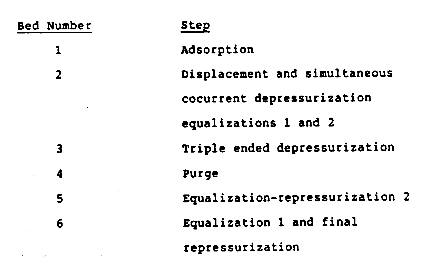
- The above separation can be efficiently carried out with a PSA unit comprising nine single beds:

- A somewhat less efficient but lower cost PSA unit can perform the same separation and can comprise six single beds:
- Ordinarily, mass transfer fronts can cause problems in single bed systems. For example, if the
mass transfer front 24 is displaced from thebed 27, which causes themass transfer front 24 depicted as curve in Figure 2 to move to the right, the less adsorbable product becomes impure. This is because the adsorbent bed becomes saturated with the adsorbed material whereupon spillage of the adsorbed material into the relatively pure effluent product occurs. Impurities can also occur if the mass transfer front is left inside of the bed when countercurrent depressurization begins. An example of this includes the flow of material in the direction of arrow 29. The lessadsorbable material 26 located at the product end of thebed 27 mixes with anadsorbable material 25 when flowing out the feed end of thebed 27. - Impurities are avoided when both the feed end of the
bed 27 and the product end of thebed 27 are simultaneously depressurized. The adsorbent bed is said to undergo "double-ended depressurization" or "DED".Adsorbed material 25 flows in the direction of arrow 29 and the lesser adsorbed material flows in the direction ofarrow 28. Thus, substantially pure adsorbed material is obtained from the feed end of thebed 27 and substantially pure less adsorbable material is obtained from the product end of thebed 27. - Figure 2 is an example of a concentration profile at the beginning of double-ended depressurization. As double-ended depressurization starts, a zero
flow plane 30 is established. To the left of the zeroflow plane 30 material in the bed flows countercurrently or in the direction of arrow 29. To the right of zeroflow plane 30 material flows cocurrently or in the direction ofarrow 28. On both sides of the zeroflow plane 30 the flow rate gradually increases and reaches a maximum at both ends of the bed. - The controlling of flow rates at both ends of the adsorbent bed are important because the relative flow rates at the adsorbent bed ends determine the position of the zero
flow plane 30. The flow rates are different at both ends as the effluent at the feed end of the bed is more voluminous than the effluent at the product end during double-ended depressurization. - The reason for this differential unloading of the bed is twofold. Firstly, the portion of the bed charged with the more adsorbable component is larger. Secondly, more of the adsorbable material is bound at the same pressure to the bed than the lesser adsorbable material. Therefore, more adsorbable material is liberated than less adsorbable material as the pressure is lowered simultaneously from both ends.
- Control of the relative flow rates at the ends can be done easily. For example, fixed position valves with critical flow can be positioned on a manifold formed by the
lines individual inlets outlets - At the completion of the double-ended depressurization, the adsorbent bed is preferably purged. This is generally done by a countercurrent purge with a less adsorbable gas. The purge effluent can be used as fuel or can be compressed and then added back into the feed gas. The adsorbent bed is then ready for another adsorption cycle and can be repressurized without a purge step.
- In cyclic operations, it is often difficult to control the flow rate of feed copurge gas and cycle time to have the concentration profile of the
mass transfer front 24 of Figure 2 in exactly the same place in each cycle. By increasing the feed and copurge flow rate or the time of adsorption, themass transfer front 24 would gradually move cocurrently towards the product end of the adsorption bed. Conversely, reducing the feed and copurge flow rate or the time of adsorption causes themass transfer front 24 to move countercurrently towards the feed end of the adsorption bed. - In accordance with the invention, it has been determined that to obtain a practically stable control over the position of the
mass transfer front 24 within the adsorption bed, it is preferable to apply at least a small mass transfer front positioning and cocurrent depressurization step prior to double-ended depressurization to move the mass transfer front cocurrently towards the product end of the adsorption bed. When the front is too far towards the product end of the bed some gas can be extracted at a side take-out from the bed. This side take-out can be, for example, a commercially available bleeder valve. - The adsorbent bed is preferably a material that contains a member selected from zeolitic molecular sieves, activated carbon, silica gel, activated alumina, and mixtures or combinations thereof. Those skilled in the art recognize that virtually any selectively adsorbent material can be used in the process of the invention.
- Gas mixtures suitable for separation typically have two or more components wherein one is more adsorbable than the other. It is often useful to think of the separable gas components as one being a "heavier" material and the other being a "lighter" material. Such characterizations of gaseous components can vary according to the type of adsorbent being used.
- The invention can be useful for two-component gas mixtures as well as for more complicated gas mixtures. For instance, air can be separated by this invention into its various subcomponents by multi-cyclic processing. That is, multiple cycles can be performed until the pure subcomponents are separated. In the first cycle, a complex gas mixture is loaded onto the beds. A displacement gas comprising substantially the most adsorbable component of the mixture is then used to "copurge" the bed to move lesser adsorbable components up-stream. Then, upon double-ended depressurization, the more adsorbable components are separated from the feed end of the bed and the less adsorbable components are separated from the product end of the bed. Subsequent cycles can then be conducted to further separate the two products of the first cycle.
Claims (15)
- A method for gas separation of adsorbable components from less adsorbable components on fixed adsorbent beds, comprising the steps of:a) flowing a feed gas mixture under adsorption pressure to an adsorbent bed to selectively adsorb components from the feed gas onto the adsorbent bed, the bed having a feed end and a product end; andb) displacing the feed gas with a gas having a higher concentration of adsorbable components, whereby less adsorbable components are displaced from a portion of the bed; andc) depressurizing the bed by taking out gas simultaneously from at least two different locations of the bed to recover substantially pure less adsorbable components at the product end of the bed and to recover the adsorbable components from at least one of the different locations; and, as appropriated) repressurizing the bed.
- A method according to claim 1, wherein the step of depressurizing comprises (i) simultaneously taking out gas from the feed end and the product end of the bed, or (ii) simultaneously taking out gas at a side takeout of the bed and at the product end of the bed; or (iii) simultaneously performing steps (i) and (ii) above.
- A method according to claim 1 or 2, further comprising the step of purging the bed with the less adsorbable components prior to the step of repressurizing.
- A method according to claim 3, wherein the step of purging is carried out with a purge gas obtained from the product end during said step of depressurizing.
- A method according to any of claims 1 to 4, wherein the steps of flowing and displacing are carried out at substantially the same pressure.
- A method according to any of claims 1 to 5, further comprising the step of depressurizing the bed from a side takeout prior to the step of depressurizing the bed by taking out gas simultaneosuly.
- A method according to any of claims 1 to 4, further comprising the step of depressurizing the bed in a cocurrent direction, the cocurrent depressurization occurring prior to the step of simultaneously depressurizing.
- A method according to claim 7, wherein the cocurrent depressurization step is performed (i) before the step of displacing; or (ii) simultaneously with the step of displacing; or (iii) after the step of displacing.
- A method according to claim 7, wherein the step of cocurrent depressurizing further comprises repressurizing other beds with a gas obtained from the product end.
- A method according to any of claims 1 to 9, wherein the step of displacing is performed using (i) fixed position valves; or (ii) volumetric compressors; or (iii) flowing the first component recovered from the feed end onto the bed.
- A method according to any of claims 1 to 10, wherein the first component comprises carbon monoxide, carbon dioxide, or methane and the second component comprises hydrogen or nitrogen.
- A method according to any of claims 1 to 11, wherein the adsorbent bed is a material that contains a member selected from zeolitic molecular sieves, activated carbon, silica gel, activated alumina, and mixtures thereof.
- A method according to any of claims 1 to 12, wherein the number of adsorbent beds is at least four.
- A method according to claim 13, wherein the number of adsorbent beds is five or six.
- A method according to any of claims 1 to 14, wherein the step of selectively adsorbing components occurs in at least one bed at any given time.
Priority Applications (1)
| Application Number | Priority Date | Filing Date | Title |
|---|---|---|---|
| AT87310920T ATE78419T1 (en) | 1986-12-11 | 1987-12-11 | GAS SEPARATION AND GAS PURIFICATION. |
Applications Claiming Priority (2)
| Application Number | Priority Date | Filing Date | Title |
|---|---|---|---|
| US06/940,612 US4723966A (en) | 1986-12-11 | 1986-12-11 | Gas separation by pressure swing adsorption |
| US940612 | 1986-12-11 |
Publications (3)
| Publication Number | Publication Date |
|---|---|
| EP0271356A2 EP0271356A2 (en) | 1988-06-15 |
| EP0271356A3 EP0271356A3 (en) | 1989-05-31 |
| EP0271356B1 true EP0271356B1 (en) | 1992-07-22 |
Family
ID=25475148
Family Applications (1)
| Application Number | Title | Priority Date | Filing Date |
|---|---|---|---|
| EP87310920A Expired - Lifetime EP0271356B1 (en) | 1986-12-11 | 1987-12-11 | Gas separation and purification |
Country Status (11)
| Country | Link |
|---|---|
| US (1) | US4723966A (en) |
| EP (1) | EP0271356B1 (en) |
| JP (1) | JPS63240915A (en) |
| KR (1) | KR920002081B1 (en) |
| CN (1) | CN1008065B (en) |
| AT (1) | ATE78419T1 (en) |
| BR (1) | BR8706710A (en) |
| CA (1) | CA1314494C (en) |
| DE (1) | DE3780590T2 (en) |
| ES (1) | ES2033885T3 (en) |
| IN (1) | IN171647B (en) |
Families Citing this family (25)
| Publication number | Priority date | Publication date | Assignee | Title |
|---|---|---|---|---|
| US4783203A (en) * | 1987-10-22 | 1988-11-08 | Union Carbide Corporation | Integrated pressure swing adsorption/membrane separation process |
| JPH02129014A (en) * | 1988-11-04 | 1990-05-17 | Mitsui Eng & Shipbuild Co Ltd | Production of carbon monoxide gas |
| US5013337A (en) * | 1988-12-06 | 1991-05-07 | Uop | Process for separating a mixture of molecular species using crystalline microporous metal sulfide compositions |
| US5126120A (en) * | 1990-10-02 | 1992-06-30 | Uop | Crystalline microporous zinc phosphate compositions |
| US5203888A (en) * | 1990-11-23 | 1993-04-20 | Uop | Pressure swing adsorption process with multiple desorption steps |
| US5122357A (en) * | 1991-03-18 | 1992-06-16 | Uop | Crystalline microporous metal oxysulfide compositions |
| US5128025A (en) * | 1991-03-18 | 1992-07-07 | Uop | Hydrocarbon conversion processes using a novel crystalline microporous metal oxysulfide composition |
| US5302362A (en) * | 1992-04-10 | 1994-04-12 | Uop | Crystalline microporous metallo-zinc phosphate compositions |
| US5449450A (en) * | 1992-04-10 | 1995-09-12 | Uop | Hydrocarbon conversion process using a crystalline microporous metallo-zinc phosphate composition |
| US5294247A (en) * | 1993-02-26 | 1994-03-15 | Air Products And Chemicals, Inc. | Adsorption process to recover hydrogen from low pressure feeds |
| US5411578A (en) * | 1994-05-10 | 1995-05-02 | Air Products And Chemicals, Inc. | Vacuum swing adsorption process with mixed repressurization and provide product depressurization |
| US6048384A (en) * | 1997-12-09 | 2000-04-11 | Smolarek; James | PSA process and system using simultaneous top and bottom evacuation of absorbent bed |
| US5997612A (en) * | 1998-07-24 | 1999-12-07 | The Boc Group, Inc. | Pressure swing adsorption process and apparatus |
| US6245127B1 (en) | 1999-05-27 | 2001-06-12 | Praxair Technology, Inc. | Pressure swing adsorption process and apparatus |
| US6660064B2 (en) * | 2002-03-08 | 2003-12-09 | Air Products And Chemicals, Inc. | Activated carbon as sole absorbent in rapid cycle hydrogen PSA |
| WO2005032693A2 (en) * | 2003-08-29 | 2005-04-14 | Velocys Inc. | Process for separating nitrogen from methane using microchannel process technology |
| US8241400B2 (en) * | 2009-07-15 | 2012-08-14 | L'air Liquide Societe Anonyme Pour L'etude Et L'exploitation Des Procedes Georges Claude | Process for the production of carbon dioxide utilizing a co-purge pressure swing adsorption unit |
| US8752390B2 (en) * | 2010-07-13 | 2014-06-17 | Air Products And Chemicals, Inc. | Method and apparatus for producing power and hydrogen |
| US8778051B2 (en) | 2012-03-15 | 2014-07-15 | Air Products And Chemicals, Inc. | Pressure swing adsorption process |
| US8715617B2 (en) | 2012-03-15 | 2014-05-06 | Air Products And Chemicals, Inc. | Hydrogen production process with low CO2 emissions |
| FR3011480B1 (en) * | 2013-10-04 | 2017-01-27 | Air Liquide | ADSORPTION METHOD WITH PRESSURE MODULATION WITH ADDITIONAL ELUTION |
| US9808755B2 (en) | 2015-07-24 | 2017-11-07 | Air Products And Chemicals, Inc. | Sour pressure swing adsorption process |
| CN107456845B (en) * | 2017-08-25 | 2023-04-04 | 西南化工研究设计院有限公司 | Pressure swing adsorption device and control method thereof |
| KR101987804B1 (en) * | 2017-11-17 | 2019-06-12 | 한국에너지기술연구원 | Pressure swing adsorption method and pressure swing adsorption apparatus |
| US11613866B1 (en) | 2019-06-14 | 2023-03-28 | Nusfc, Llc | Retainer for closure device |
Citations (1)
| Publication number | Priority date | Publication date | Assignee | Title |
|---|---|---|---|---|
| GB1536995A (en) * | 1976-02-04 | 1978-12-29 | Linde Ag | Separation of gas mixtures |
Family Cites Families (17)
| Publication number | Priority date | Publication date | Assignee | Title |
|---|---|---|---|---|
| US2944627A (en) * | 1958-02-12 | 1960-07-12 | Exxon Research Engineering Co | Method and apparatus for fractionating gaseous mixtures by adsorption |
| US2978407A (en) * | 1958-05-28 | 1961-04-04 | Exxon Research Engineering Co | Molecular sieve separation process |
| FR1306111A (en) * | 1960-09-16 | 1962-10-13 | Union Carbide Corp | Adsorption separation process |
| NL297067A (en) * | 1962-09-04 | 1900-01-01 | ||
| US3430418A (en) * | 1967-08-09 | 1969-03-04 | Union Carbide Corp | Selective adsorption process |
| FR2044058A5 (en) * | 1969-05-07 | 1971-02-19 | Air Liquide | |
| US3738087A (en) * | 1971-07-01 | 1973-06-12 | Union Carbide Corp | Selective adsorption gas separation process |
| US4011065A (en) * | 1974-01-09 | 1977-03-08 | Bergwerksverband Gmbh | Process for the enrichment of gases |
| US3986849A (en) * | 1975-11-07 | 1976-10-19 | Union Carbide Corporation | Selective adsorption process |
| US4093429A (en) * | 1975-12-19 | 1978-06-06 | General Electric Company | Gas separation system |
| US4264338A (en) * | 1977-11-02 | 1981-04-28 | Monsanto Company | Method for separating gases |
| US4354859A (en) * | 1981-08-06 | 1982-10-19 | Union Carbide Corporation | Enhanced gas separation by selective adsorption |
| US4398926A (en) * | 1982-04-23 | 1983-08-16 | Union Carbide Corporation | Enhanced hydrogen recovery from low purity gas streams |
| US4512780A (en) * | 1983-11-08 | 1985-04-23 | Union Carbide Corporation | Pressure swing adsorption with intermediate product recovery |
| ZA849756B (en) * | 1983-12-15 | 1986-06-25 | Bergwerksverband Gmbh | Process for isolating and recovering gases which are relatively strongly adsorbable on adsorbents from gas mixtures which otherwise essentially contain only less strongly adsorbable gases |
| US4589888A (en) * | 1984-10-05 | 1986-05-20 | Union Carbide Corporation | Pressure swing adsorption process |
| DE3528909A1 (en) * | 1985-08-12 | 1987-02-19 | Linde Ag | PRESSURE EXCHANGE ADDING METHOD |
-
1986
- 1986-12-11 US US06/940,612 patent/US4723966A/en not_active Expired - Fee Related
-
1987
- 1987-12-10 BR BR8706710A patent/BR8706710A/en not_active IP Right Cessation
- 1987-12-11 AT AT87310920T patent/ATE78419T1/en not_active IP Right Cessation
- 1987-12-11 EP EP87310920A patent/EP0271356B1/en not_active Expired - Lifetime
- 1987-12-11 ES ES198787310920T patent/ES2033885T3/en not_active Expired - Lifetime
- 1987-12-11 JP JP62312388A patent/JPS63240915A/en active Granted
- 1987-12-11 IN IN1065/DEL/87A patent/IN171647B/en unknown
- 1987-12-11 CN CN87107532A patent/CN1008065B/en not_active Expired
- 1987-12-11 CA CA000554115A patent/CA1314494C/en not_active Expired - Fee Related
- 1987-12-11 KR KR1019870014130A patent/KR920002081B1/en not_active Expired
- 1987-12-11 DE DE8787310920T patent/DE3780590T2/en not_active Expired - Lifetime
Patent Citations (1)
| Publication number | Priority date | Publication date | Assignee | Title |
|---|---|---|---|---|
| GB1536995A (en) * | 1976-02-04 | 1978-12-29 | Linde Ag | Separation of gas mixtures |
Also Published As
| Publication number | Publication date |
|---|---|
| CA1314494C (en) | 1993-03-16 |
| JPH0321207B2 (en) | 1991-03-22 |
| DE3780590T2 (en) | 1992-12-17 |
| ES2033885T3 (en) | 1993-04-01 |
| IN171647B (en) | 1992-11-28 |
| BR8706710A (en) | 1988-07-19 |
| JPS63240915A (en) | 1988-10-06 |
| KR880007110A (en) | 1988-08-26 |
| CN87107532A (en) | 1988-08-03 |
| ATE78419T1 (en) | 1992-08-15 |
| KR920002081B1 (en) | 1992-03-10 |
| EP0271356A2 (en) | 1988-06-15 |
| CN1008065B (en) | 1990-05-23 |
| US4723966A (en) | 1988-02-09 |
| DE3780590D1 (en) | 1992-08-27 |
| EP0271356A3 (en) | 1989-05-31 |
Similar Documents
| Publication | Publication Date | Title |
|---|---|---|
| US4723966A (en) | Gas separation by pressure swing adsorption | |
| US4171207A (en) | Separation of multicomponent gas mixtures by pressure swing adsorption | |
| EP0194334B1 (en) | Pressure swing adsorption with intermediate product recovery | |
| EP0092153B1 (en) | Pressure swing adsorption system | |
| US5792239A (en) | Separation of gases by pressure swing adsorption | |
| EP0579289B1 (en) | Separation of gas mixtures | |
| US4070164A (en) | Adsorption-desorption pressure swing gas separation | |
| US3430418A (en) | Selective adsorption process | |
| EP0462778B1 (en) | Pressure swing adsorption method for separating gaseous mixtures | |
| US5882380A (en) | Pressure swing adsorption process with a single adsorbent bed | |
| US4482361A (en) | Pressure swing adsorption process | |
| US4171206A (en) | Separation of multicomponent gas mixtures | |
| US4340398A (en) | Pressure swing adsorption recovery | |
| EP0620035A1 (en) | Pressure swing adsorption/desorption process with multiple countercurrent de-pressurization steps | |
| US5906673A (en) | Pressure swing system with auxiliary adsorbent bed | |
| USRE31014E (en) | Separation of multicomponent gas mixtures | |
| EP0305663B1 (en) | Pressure swing adsorption control method and apparatus | |
| EP1101522B1 (en) | Pressure swing adsorption process | |
| EP0273723A2 (en) | Separating a gas enriched in oxygen | |
| EP0385174A2 (en) | Adsorptive process for separating multicomponent gas mixtures | |
| EP0489555A1 (en) | Hydrogen and carbon monoxide production by hydrocarbon steam reforming and pressure swing adsorption purification | |
| EP0699467B1 (en) | Simultaneous step pressure swing adsorption process | |
| EP0513747A1 (en) | Gas separation process | |
| EP0361541A2 (en) | Pressure swing adsorption process | |
| EP0215843B1 (en) | Enhanced pressure swing adsorption process and system |
Legal Events
| Date | Code | Title | Description |
|---|---|---|---|
| PUAI | Public reference made under article 153(3) epc to a published international application that has entered the european phase |
Free format text: ORIGINAL CODE: 0009012 |
|
| AK | Designated contracting states |
Kind code of ref document: A2 Designated state(s): AT BE CH DE ES FR GB GR IT LI LU NL SE |
|
| PUAL | Search report despatched |
Free format text: ORIGINAL CODE: 0009013 |
|
| AK | Designated contracting states |
Kind code of ref document: A3 Designated state(s): AT BE CH DE ES FR GB GR IT LI LU NL SE |
|
| 17P | Request for examination filed |
Effective date: 19890621 |
|
| 17Q | First examination report despatched |
Effective date: 19901116 |
|
| RAP1 | Party data changed (applicant data changed or rights of an application transferred) |
Owner name: UOP (A NEW YORK GENERAL PARTNERSHIP) |
|
| GRAA | (expected) grant |
Free format text: ORIGINAL CODE: 0009210 |
|
| AK | Designated contracting states |
Kind code of ref document: B1 Designated state(s): AT BE CH DE ES FR GB GR IT LI LU NL SE |
|
| PG25 | Lapsed in a contracting state [announced via postgrant information from national office to epo] |
Ref country code: SE Effective date: 19920722 Ref country code: LI Effective date: 19920722 Ref country code: GR Free format text: LAPSE BECAUSE OF FAILURE TO SUBMIT A TRANSLATION OF THE DESCRIPTION OR TO PAY THE FEE WITHIN THE PRESCRIBED TIME-LIMIT Effective date: 19920722 Ref country code: CH Effective date: 19920722 |
|
| REF | Corresponds to: |
Ref document number: 78419 Country of ref document: AT Date of ref document: 19920815 Kind code of ref document: T |
|
| REF | Corresponds to: |
Ref document number: 3780590 Country of ref document: DE Date of ref document: 19920827 |
|
| ET | Fr: translation filed | ||
| ITF | It: translation for a ep patent filed | ||
| REG | Reference to a national code |
Ref country code: CH Ref legal event code: PL |
|
| PG25 | Lapsed in a contracting state [announced via postgrant information from national office to epo] |
Ref country code: LU Free format text: LAPSE BECAUSE OF NON-PAYMENT OF DUE FEES Effective date: 19921231 |
|
| REG | Reference to a national code |
Ref country code: ES Ref legal event code: FG2A Ref document number: 2033885 Country of ref document: ES Kind code of ref document: T3 |
|
| PLBE | No opposition filed within time limit |
Free format text: ORIGINAL CODE: 0009261 |
|
| STAA | Information on the status of an ep patent application or granted ep patent |
Free format text: STATUS: NO OPPOSITION FILED WITHIN TIME LIMIT |
|
| 26N | No opposition filed | ||
| PGFP | Annual fee paid to national office [announced via postgrant information from national office to epo] |
Ref country code: FR Payment date: 20001117 Year of fee payment: 14 |
|
| PGFP | Annual fee paid to national office [announced via postgrant information from national office to epo] |
Ref country code: NL Payment date: 20001120 Year of fee payment: 14 |
|
| PGFP | Annual fee paid to national office [announced via postgrant information from national office to epo] |
Ref country code: GB Payment date: 20001121 Year of fee payment: 14 Ref country code: AT Payment date: 20001121 Year of fee payment: 14 |
|
| PGFP | Annual fee paid to national office [announced via postgrant information from national office to epo] |
Ref country code: DE Payment date: 20001122 Year of fee payment: 14 |
|
| PGFP | Annual fee paid to national office [announced via postgrant information from national office to epo] |
Ref country code: BE Payment date: 20001207 Year of fee payment: 14 |
|
| PGFP | Annual fee paid to national office [announced via postgrant information from national office to epo] |
Ref country code: ES Payment date: 20010112 Year of fee payment: 14 |
|
| PG25 | Lapsed in a contracting state [announced via postgrant information from national office to epo] |
Ref country code: GB Free format text: LAPSE BECAUSE OF NON-PAYMENT OF DUE FEES Effective date: 20011211 Ref country code: AT Free format text: LAPSE BECAUSE OF NON-PAYMENT OF DUE FEES Effective date: 20011211 |
|
| PG25 | Lapsed in a contracting state [announced via postgrant information from national office to epo] |
Ref country code: BE Free format text: LAPSE BECAUSE OF NON-PAYMENT OF DUE FEES Effective date: 20011231 |
|
| REG | Reference to a national code |
Ref country code: GB Ref legal event code: IF02 |
|
| BERE | Be: lapsed |
Owner name: UOP (A NEW YORK GENERAL PARTNERSHIP) Effective date: 20011231 |
|
| PG25 | Lapsed in a contracting state [announced via postgrant information from national office to epo] |
Ref country code: NL Free format text: LAPSE BECAUSE OF NON-PAYMENT OF DUE FEES Effective date: 20020701 |
|
| PG25 | Lapsed in a contracting state [announced via postgrant information from national office to epo] |
Ref country code: DE Free format text: LAPSE BECAUSE OF NON-PAYMENT OF DUE FEES Effective date: 20020702 |
|
| GBPC | Gb: european patent ceased through non-payment of renewal fee |
Effective date: 20011211 |
|
| PG25 | Lapsed in a contracting state [announced via postgrant information from national office to epo] |
Ref country code: FR Free format text: LAPSE BECAUSE OF NON-PAYMENT OF DUE FEES Effective date: 20020830 |
|
| NLV4 | Nl: lapsed or anulled due to non-payment of the annual fee |
Effective date: 20020701 |
|
| REG | Reference to a national code |
Ref country code: FR Ref legal event code: ST |
|
| PG25 | Lapsed in a contracting state [announced via postgrant information from national office to epo] |
Ref country code: ES Free format text: LAPSE BECAUSE OF NON-PAYMENT OF DUE FEES Effective date: 20021212 |
|
| REG | Reference to a national code |
Ref country code: ES Ref legal event code: FD2A Effective date: 20030113 |
|
| PG25 | Lapsed in a contracting state [announced via postgrant information from national office to epo] |
Ref country code: IT Free format text: LAPSE BECAUSE OF NON-PAYMENT OF DUE FEES;WARNING: LAPSES OF ITALIAN PATENTS WITH EFFECTIVE DATE BEFORE 2007 MAY HAVE OCCURRED AT ANY TIME BEFORE 2007. THE CORRECT EFFECTIVE DATE MAY BE DIFFERENT FROM THE ONE RECORDED. Effective date: 20051211 |