EP0269264B1 - Ferrofluid seal for a stationary shaft and a rotating hub - Google Patents
Ferrofluid seal for a stationary shaft and a rotating hub Download PDFInfo
- Publication number
- EP0269264B1 EP0269264B1 EP87309513A EP87309513A EP0269264B1 EP 0269264 B1 EP0269264 B1 EP 0269264B1 EP 87309513 A EP87309513 A EP 87309513A EP 87309513 A EP87309513 A EP 87309513A EP 0269264 B1 EP0269264 B1 EP 0269264B1
- Authority
- EP
- European Patent Office
- Prior art keywords
- shaft
- bearing
- ferrofluid
- gap
- rotation
- Prior art date
- Legal status (The legal status is an assumption and is not a legal conclusion. Google has not performed a legal analysis and makes no representation as to the accuracy of the status listed.)
- Expired - Lifetime
Links
- 239000011554 ferrofluid Substances 0.000 title claims description 73
- 230000008602 contraction Effects 0.000 claims description 19
- 239000011553 magnetic fluid Substances 0.000 claims description 14
- 239000012530 fluid Substances 0.000 description 43
- 239000010408 film Substances 0.000 description 20
- 238000010586 diagram Methods 0.000 description 15
- 239000000696 magnetic material Substances 0.000 description 6
- 230000000717 retained effect Effects 0.000 description 5
- 239000000314 lubricant Substances 0.000 description 4
- 230000001050 lubricating effect Effects 0.000 description 4
- 230000009977 dual effect Effects 0.000 description 3
- 230000005499 meniscus Effects 0.000 description 3
- 229910000831 Steel Inorganic materials 0.000 description 2
- 239000010959 steel Substances 0.000 description 2
- 229910000906 Bronze Inorganic materials 0.000 description 1
- 230000001154 acute effect Effects 0.000 description 1
- 230000004888 barrier function Effects 0.000 description 1
- 239000011324 bead Substances 0.000 description 1
- 239000010974 bronze Substances 0.000 description 1
- 238000010276 construction Methods 0.000 description 1
- 239000000356 contaminant Substances 0.000 description 1
- 238000011109 contamination Methods 0.000 description 1
- KUNSUQLRTQLHQQ-UHFFFAOYSA-N copper tin Chemical compound [Cu].[Sn] KUNSUQLRTQLHQQ-UHFFFAOYSA-N 0.000 description 1
- 230000007717 exclusion Effects 0.000 description 1
- 230000004907 flux Effects 0.000 description 1
- 230000003993 interaction Effects 0.000 description 1
- 239000006249 magnetic particle Substances 0.000 description 1
- 239000000463 material Substances 0.000 description 1
- 230000004048 modification Effects 0.000 description 1
- 238000012986 modification Methods 0.000 description 1
- 239000010409 thin film Substances 0.000 description 1
- 230000003313 weakening effect Effects 0.000 description 1
Images


Classifications
-
- F—MECHANICAL ENGINEERING; LIGHTING; HEATING; WEAPONS; BLASTING
- F16—ENGINEERING ELEMENTS AND UNITS; GENERAL MEASURES FOR PRODUCING AND MAINTAINING EFFECTIVE FUNCTIONING OF MACHINES OR INSTALLATIONS; THERMAL INSULATION IN GENERAL
- F16C—SHAFTS; FLEXIBLE SHAFTS; ELEMENTS OR CRANKSHAFT MECHANISMS; ROTARY BODIES OTHER THAN GEARING ELEMENTS; BEARINGS
- F16C33/00—Parts of bearings; Special methods for making bearings or parts thereof
- F16C33/72—Sealings
- F16C33/74—Sealings of sliding-contact bearings
-
- F—MECHANICAL ENGINEERING; LIGHTING; HEATING; WEAPONS; BLASTING
- F16—ENGINEERING ELEMENTS AND UNITS; GENERAL MEASURES FOR PRODUCING AND MAINTAINING EFFECTIVE FUNCTIONING OF MACHINES OR INSTALLATIONS; THERMAL INSULATION IN GENERAL
- F16C—SHAFTS; FLEXIBLE SHAFTS; ELEMENTS OR CRANKSHAFT MECHANISMS; ROTARY BODIES OTHER THAN GEARING ELEMENTS; BEARINGS
- F16C33/00—Parts of bearings; Special methods for making bearings or parts thereof
- F16C33/02—Parts of sliding-contact bearings
- F16C33/04—Brasses; Bushes; Linings
- F16C33/06—Sliding surface mainly made of metal
- F16C33/10—Construction relative to lubrication
- F16C33/1025—Construction relative to lubrication with liquid, e.g. oil, as lubricant
- F16C33/103—Construction relative to lubrication with liquid, e.g. oil, as lubricant retained in or near the bearing
- F16C33/1035—Construction relative to lubrication with liquid, e.g. oil, as lubricant retained in or near the bearing by a magnetic field acting on a magnetic liquid
-
- F—MECHANICAL ENGINEERING; LIGHTING; HEATING; WEAPONS; BLASTING
- F16—ENGINEERING ELEMENTS AND UNITS; GENERAL MEASURES FOR PRODUCING AND MAINTAINING EFFECTIVE FUNCTIONING OF MACHINES OR INSTALLATIONS; THERMAL INSULATION IN GENERAL
- F16J—PISTONS; CYLINDERS; SEALINGS
- F16J15/00—Sealings
- F16J15/16—Sealings between relatively-moving surfaces
- F16J15/40—Sealings between relatively-moving surfaces by means of fluid
- F16J15/43—Sealings between relatively-moving surfaces by means of fluid kept in sealing position by magnetic force
-
- H—ELECTRICITY
- H02—GENERATION; CONVERSION OR DISTRIBUTION OF ELECTRIC POWER
- H02K—DYNAMO-ELECTRIC MACHINES
- H02K5/00—Casings; Enclosures; Supports
- H02K5/04—Casings or enclosures characterised by the shape, form or construction thereof
- H02K5/12—Casings or enclosures characterised by the shape, form or construction thereof specially adapted for operating in liquid or gas
- H02K5/124—Sealing of shafts
-
- H—ELECTRICITY
- H02—GENERATION; CONVERSION OR DISTRIBUTION OF ELECTRIC POWER
- H02K—DYNAMO-ELECTRIC MACHINES
- H02K5/00—Casings; Enclosures; Supports
- H02K5/04—Casings or enclosures characterised by the shape, form or construction thereof
- H02K5/16—Means for supporting bearings, e.g. insulating supports or means for fitting bearings in the bearing-shields
- H02K5/167—Means for supporting bearings, e.g. insulating supports or means for fitting bearings in the bearing-shields using sliding-contact or spherical cap bearings
- H02K5/1677—Means for supporting bearings, e.g. insulating supports or means for fitting bearings in the bearing-shields using sliding-contact or spherical cap bearings radially supporting the rotor around a fixed spindle; radially supporting the rotor directly
-
- H—ELECTRICITY
- H02—GENERATION; CONVERSION OR DISTRIBUTION OF ELECTRIC POWER
- H02K—DYNAMO-ELECTRIC MACHINES
- H02K5/00—Casings; Enclosures; Supports
- H02K5/04—Casings or enclosures characterised by the shape, form or construction thereof
- H02K5/16—Means for supporting bearings, e.g. insulating supports or means for fitting bearings in the bearing-shields
- H02K5/173—Means for supporting bearings, e.g. insulating supports or means for fitting bearings in the bearing-shields using bearings with rolling contact, e.g. ball bearings
- H02K5/1737—Means for supporting bearings, e.g. insulating supports or means for fitting bearings in the bearing-shields using bearings with rolling contact, e.g. ball bearings radially supporting the rotor around a fixed spindle; radially supporting the rotor directly
-
- H—ELECTRICITY
- H02—GENERATION; CONVERSION OR DISTRIBUTION OF ELECTRIC POWER
- H02K—DYNAMO-ELECTRIC MACHINES
- H02K7/00—Arrangements for handling mechanical energy structurally associated with dynamo-electric machines, e.g. structural association with mechanical driving motors or auxiliary dynamo-electric machines
- H02K7/08—Structural association with bearings
- H02K7/086—Structural association with bearings radially supporting the rotor around a fixed spindle; radially supporting the rotor directly
-
- F—MECHANICAL ENGINEERING; LIGHTING; HEATING; WEAPONS; BLASTING
- F16—ENGINEERING ELEMENTS AND UNITS; GENERAL MEASURES FOR PRODUCING AND MAINTAINING EFFECTIVE FUNCTIONING OF MACHINES OR INSTALLATIONS; THERMAL INSULATION IN GENERAL
- F16C—SHAFTS; FLEXIBLE SHAFTS; ELEMENTS OR CRANKSHAFT MECHANISMS; ROTARY BODIES OTHER THAN GEARING ELEMENTS; BEARINGS
- F16C2380/00—Electrical apparatus
- F16C2380/26—Dynamo-electric machines or combinations therewith, e.g. electro-motors and generators
-
- H—ELECTRICITY
- H02—GENERATION; CONVERSION OR DISTRIBUTION OF ELECTRIC POWER
- H02K—DYNAMO-ELECTRIC MACHINES
- H02K7/00—Arrangements for handling mechanical energy structurally associated with dynamo-electric machines, e.g. structural association with mechanical driving motors or auxiliary dynamo-electric machines
- H02K7/08—Structural association with bearings
- H02K7/09—Structural association with bearings with magnetic bearings
Definitions
- This invention relates to ferrofluid seals for bearings and spindles which are constructed with a stationary shaft and a rotating hub.
- a ferrofluid seal generally consists of a magnet and pole pieces which, together with the bearing shaft (which is comprised of magnetic material), form a complete magnetic circuit.
- the circuit includes a small gap between the pole pieces and the bearing shaft in which an intense magnetic field is produced by the magnet. This field traps a magnetic fluid (a low-vapor pressure fluid containing colloidal magnetic particles) and retains it in position in the gap.
- the magnetic fluid bridges the gap and forms a physical barrier which prevents lubricant loss from the bearing.
- a properly-designed ferrofluid seal can retain the magnetic fluid in position and, thus, maintain the seal over a variety of operating temperatures.
- one problem with conventional ferrofluid seals is caused by changes in the volume of the ferrofluid in the seal gap due to temperature variations. Such a problem is particularly acute in fluid-film bearings in which the ferrofluid is also used as the internal film lubricant. In this latter type of bearing, the large amount of magnetic lubricating fluid retained in the bearing is subject to substantial volume changes caused by temperature fluctuations.
- an increase in bearing temperature causes the magnetic lubricating fluid to expand. Since the bearing is generally sealed, fluid expansion tends to force portions of the fluid through the magnetic field in the seal gap. At high operating temperatures, the fluid can expand sufficiently to force portions of the fluid past the gap area and outside the magnetic field zone. When the fluid has been pushed out of the field zone it becomes essentially free and, when the bearing is rotating, drops of fluid splash out of the seal, in turn, causing fluid loss, contamination and the eventual failure of the bearing.
- the inside surface of the gap-forming pole piece is tapered or chamfered to increase the radial width of the gap towards the exterior face of the seal.
- This chamfering converts the annular gap into a wedge-shaped annular cap which increases in volume towards the exterior of the seal.
- the increase in volume in the gap allows for fluid expansion due to temperature increase and accommodates the excess fluid volume while still maintaining the fluid subject to the magnetic field, thereby preventing fluid splash and leakage.
- An example of such a seal is to be found in French Patent Specification FR-A-2,313,592.
- a ferrofluid seal with a chamfered pole piece produces generally satisfactory results in bearing configurations in which the bearing housing or hub is stationary and the bearing shaft rotates.
- the configuration is generally limited to a low operating temperature and low hub rotational speeds. This is because, at high operating temperatures and at high rotational speeds, expansion of the ferrofluid forces portions of the fluid into the gap as with the rotating shaft construction - as the fluid moves into the gap it moves radially outward because the gap expands in that direction.
- the housing since the housing is now rotating, it carries the adjacent fluid along with it and the fluid at the outer edge of the gap is subject to centrifugal force. This force causes further outward movement of the fluid into the gap which causes the fluid in the seal gap to creep up the sloping face of the gap-forming pole.
- the creeping problem is further compounded by a weakening of the local magnetic field strength at the outer positions due to increasing gap width. Eventually, drops of the fluid splash over the edge of the pole piece causing fluid loss and eventual bearing failure.
- the present invention overcomes the foregoing problems by providing a taper (60) on the shaft forming a portion of the gap into an annular wedge-shaped gap having a sloping wall which extends radially towards the axis of rotation of said shaft and in a direction towards said external environment which allows for expansion of the ferrofluid, the inner surface (36) of the gap forming pole piece opposite the taper of the shaft being straight and located at a constant radius from the axis of rotation of the shaft to maintain the ferrofluid in place under high temperature and rotational speeds.
- the shaft and the pole piece form a wedge-shaped annular gap into which the ferrofluid can expand at high operating temperatures
- the expansion produces movement of the fluid in the gap towards the axis of rotation rather than away from the axis of rotation. This movement is counteracted by centrifugal force acting on the fluid.
- centrifugal force is a maximum at the outer edge of the gap, the fluid is retained even under high rotational speeds because the pole piece which defines the outer gap edge has straight walls making it difficult for the fluid to creep over the edge of the pole piece.
- Alternative embodiments of the invention use dual tapers on the bearing shaft in the gap area to accommodate both fluid expansion and fluid contraction.
- the shaft may be tapered to accommodate fluid expansion and the pole face or magnet may be chamfered on the interior portion of its inner surface to provide for fluid contraction.
- the inner surface of the gap-forming pole piece is straight to maintain the ferrofluid in place under high temperatures and rotational speeds.
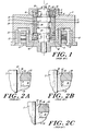
- Figure 1 is a cross-sectional view of a magnetic fluid-film bearing with a stationary shaft and rotation hub in which the fluid is confined by a conventional ferrofluid seal.
- Figure 2A, 2B and 2C are expanded cross-sectional diagrams showing deformation of the magnetic fluid meniscus in the seal area of a stationary shaft design under increasing rotational speeds.
- Figure 3 shows a cross-sectional diagram of a magnetic fluid-film bearing incorporating the inventive seal design.
- Figure 4 is a cross sectional diagram of a magnetic fluid-film bearing with an inventive ferrofluid seal incorporating a dual taper on the stationary shaft to accommodate both expansion and contraction of the magnetic fluid.
- Figure 5 is a cross-sectional diagram of a magnetic fluid-film bearing incorporating a ferrofluid seal with a taper on the shaft and a chamfer on the inside face of the gap-forming pole piece to accommodate both expansion and contraction of the magnetic fluid.
- Figure 6 is a cross-sectional diagram of a magnetic fluid-film bearing incorporating a ferrofluid seal which is a variation of the seal shown in Figure 5, which seal utilizes a taper on the stationary shaft and a chamfered face on the seal magnet to accommodate both expansion and contraction of the magnetic fluid.
- Figure 7 is a cross-sectional diagram of a magnetic fluid-film bearing incorporating a ferrofluid seal with a radially-polarized magnet and a taper on the shaft to accommodate expansion and contraction of the magnetic fluid.
- Figure 8 is a cross-sectional diagram of the inventive seal incorporated in a bearing application with a stationary spindle and rotating hub and utilizing ball bearings.
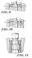
- Figure 9 is a cross-sectional diagram of a ferrofluid seal for use in a ball-bearing spindle with a single pole piece.
- Figure 10 is a cross-sectional diagram of a ferrofluid seal for use in a ball-bearing spindle with a radially-polarized magnet.
- Figure 11 is a cross-sectional diagram of an additional embodiment of magnetic fluid film bearing incorporating a ferrofluid seal with a double taper on the shaft to maximise shaft stiffness.
- Figure 1 shows a cross-sectional diagram of a conventional magnetic fluid film radial/thrust bearing used in a stationary shaft and rotating hub design in which the bearing consists of a fluid-film bearing with a stationary shaft 2 and rotating hub or rotor 4.
- a bearing may for example be used as the spindle bearing in a small electric motor which is comprised of rotor 4 and stator 6.
- Rotor 4 is driven by the interaction of armature coils 8 and permanent magnets 10 in a conventional fashion.
- the operation of the motor is not important for an understanding of the invention and, accordingly, will not be described further herein.
- Shaft 2 is comprised of a magnetic material such as steel and is either machined to provide two film bearing surfaces 12 or a separate piece is press fit onto shaft 2 to provide surfaces 12.
- Surfaces 12 form two fluid film bearings with cylindrical sleeve 14, which provide for radial alignment of the rotor 4.
- Sleeve 14 is formed of a non-magnetic bearing material such as bronze and does not actually contact bearing surfaces 12, but instead is separated by a thin film of lubricant.
- Axial alignment of rotor 4 is controlled by a pair of thrust bearings affixed to the shaft on both sides of sleeve 14.
- the upper thrust bearing is constructed from an annular thrust bearing ring 18 which is affixed to shaft 2 and operates against the upper face 16 of sleeve 14.
- the lower thrust bearing is comprised of thrust bearing ring 20 which operates against the lower face 22 of sleeve 14.
- Thrust bearing rings 18 and 20 are usually made of magnetic steel.
- the space 28 between shaft 2 and the inner surface of sleeve 14 is filled with a conventional lubricating ferrofluid, 38, which serves to lubricate the film bearing surfaces between surfaces 12 and sleeve 14 and thrust bearing rings 18 and 20 and sleeve 14.
- a reserve of ferrofluid is kept in reservoir 24 which communicates with annular space 28 by means of orifice 26.
- the ferrolubricant is retained in the bearing by means of two ferrofluid seals located at either end of the bearing.
- Each of these seals is comprised of a magnet and an associated pole piece.
- the ferrofluid seal at the upper end of shaft 2 is comprised of an annular magnet 30 which is axially-polarized.
- the magnet is adjacent to annular pole piece 32 which is comprised of magnetic material.
- the magnet circuit includes a gap 3 between pole piece 32 and shaft 2.
- the concentration of the magnetic field in gap 3 confines ferrofluid 38 in the gap and prevents leakage of the fluid out of the bearing.
- a similar ferrofluid seal is formed from annular magnet 42 and pole piece 40 at the lower end of the bearing assembly.
- ferrofluid 38 which lubricates the bearing, is subject to expansion and contraction due to temperature variations which occur during the operation of the bearing.
- the inner surface of pole piece 32 is typically chamfered away from the shaft to form a sloping face 36.
- the sloping face converts gap 3 into a wedge-shaped annular gap with a volume that increases in a direction towards the exterior of the bearing.
- ferrofluid 38 can expand into this gap and be magnetically held without being forced out of the seal area if internal pressure develops or if the ferrolubricant in the bearing expands.
- Figure 2A is an expanded cross-sectional diagram of shaft 2, pole piece 32 and magnet 30 in the vicinity of the gap 3.
- Figure 2A shows that ferrofluid 38, under moderate temperature and low rotational speeds, forms a meniscus 50 as it expands into the wedge-shaped portion 37 of the gap 3. Increased expansion causes the fluid to move outward and up the sloping face 36 of pole piece 32.
- the creeping problem is further exacerbated by the fact that as the bulge creeps up face 36 of the pole piece 32, the local magnetic field weakens due to the widening gap between the pole piece face and the shaft. Eventually, a drop of ferrofluid shears off the main mass and escapes from the seal. In this manner, a continual loss of ferrofluid will cause the bearing to fail.
- Figure 3 shows a motor application identical to that shown in Figure 1 (a stationary shaft and rotating hub) in which the ferrofluid seals have been constructed in accordance with the present invention to extend the operating range of the magnetic fluid-film bearing.
- components that are identical to those shown in Figure 1 have been given identical numeral designations.
- the main bearing assembly is identical to that shown in Figure 1.
- the ferrofluid seals have been modified to eliminate ferrofluid splash.
- the inner surface 36 of pole piece 32 is not chamfered as in the prior art design. Instead the inner surface is "straight" and located at a constant radius from the centerline of shaft 2.
- shaft 2 now has a tapered portion 60 which, together with the inner surface 36 of pole piece 32, forms a wedge-shaped annular gap which allows for expansion of ferrofluid 38 as in the prior art design.
- the gap volume increases towards the axis of rotation and the inward radial movement of the fluid due to thermal expansion is now in an opposite direction to the movement produced by centrifugal force.
- expansion tends to move the fluid towards the axis of rotation while centrifugal force tends to move the fluid away from the axis of rotation.
- the inner surface 36 of pole piece 32 is essentially vertical and the creeping of the fluid along a sloping face is eliminated.
- ferrofluid splash is eliminated even at high operating temperatures.
- Shaft 2 is similarly tapered at its lower end 64 in order to allow for expansion of the ferrofluid in the lower ferrofluid seal.
- Figure 4 is a partial cross-sectional diagram of the motor and bearing assembly shown in Figures 1 and 3.
- the ferrofluid seal shown in Figure 4 has been modified to include a dual taper at surfaces 60 and 62 of shaft 2.
- This second illustrative embodiment accommodates both expansion and contraction of the ferrofluid 38.
- contraction of ferrofluid 38 within the bearing can reduce the volume of the ferrofluid sufficiently that the ferrofluid is drawn out of the seal gap area and away from the influence of the magnetic field. Once the ferrofluid is no longer entrapped by the magnetic field, the seal is no longer effective as an exclusion seal and air and other contaminants may enter and become entrained in the ferrolubricant causing eventual bearing failure.
- the inner tapering surface, 62 as shown in Figure 4, creates an inward-facing, wedge-shaped gap which accommodates contraction of the ferrofluid while still retaining it in the influence of the magnetic field.
- the gap volume increases, thus accommodating larger volume changes without allowing the ferrofluid outside the magnetic field area.
- Figure 5 shows a partial cross-sectional diagram of an additional illustrative embodiment which accommodates both expansion and contraction of ferrofluid 38.
- shaft 2 has been tapered at surface 60 in order to accommodate expansion of ferrofluid 38 as in the previous embodiments.
- surface 36 of pole piece 32 has been chamfered at its interior surface edge 37 to provide the second wedge-shaped annular gap that allows for contraction of the ferrofluid.
- Figure 6 shows an a cross section of another illustrative embodiment which is a modification of the arrangement shown in Figure 5.
- a wedge-shaped gap to accommodate contraction of the ferrofluid is formed by chamfering the lower face of magnet 30 instead of the lower face of pole piece 32 as shown in Figure 5.
- Figure 7 is a partial cross-sectional diagram which shows a tapered shaft 2 used with a radially-polarized magnet 30 which configuration eliminates the pole piece. A wedge-shaped annular gap is now formed between taper 60 of shaft 2 and the inner face 31 of magnet 30. In order to form a complete magnetic circuit (as shown by arrows 34), an additional magnetic sleeve 29 is used with this embodiment because housing 4 is non-magnetic.
- FIGs 8, 9 and 10 show illustrative embodiments of ball-bearing spindles that incorporate the inventive ferrofluid seal principles.
- shaft 2 is supported by a ball bearing, shown schematically as bearing 80, rather than by a magnetic fluid-film bearing as discussed with the previous embodiments.
- Bearing 80 may be lubricated with conventional lubricants and is sealed by means of a ferrofluid seal consisting of pole pieces 82 and 84, magnet 30 and ferrofluid 38.
- a magnetic circuit (illustrated by arrows 34) is completed through pole piece 82, magnet 30, pole piece 84 and shaft 2.
- the magnetic field concentrated in gap 3 between pole piece 82 and shaft 2 traps an annular bead of ferrofluid 38 which forms a magnetic fluid seal.
- Shaft 2 is comprised of magnetic material and has been tapered at face 60 in order to form a wedge-shaped gap which allows for an additional fluid storage region in the seal area so that more fluid can be retained in the seal for longer life and reliability.
- Figure 9 shows a similar design in which a single pole piece 82 is used to form the ferrofluid seal, the magnetic path (as shown by arrows 34) now being completed through bearing 80 instead of a second pole piece.
- shaft 2 is comprised of a magnetic material.
- Figure 10 shows still another embodiment which uses a radially-polarized magnet 30 that eliminates both pole pieces 32 and 80.
- the magnetic circuit as shown by arrows 34, is completed through magnet 30, ball bearing 80 and magnetic housing 4, and ring 86 which is comprised of non-magnetic material.
- Figure 11 discloses another embodiment of a magnetic fluid film bearing which uses a taper, 60, to accommodate expansion of the ferrofluid as set forth in the previous designs.
- a second taper 62 located immediatley above taper 60 brings shaft 2 back to its original diameter.
- the double taper increases the external diameter of the shaft which provides for maximum stiffness of the shaft outside the bearing area.
- This seal design may be used in either or both of the upper or lower bearing in bearing designs such as that shown in Figure 3.
Landscapes
- Engineering & Computer Science (AREA)
- General Engineering & Computer Science (AREA)
- Power Engineering (AREA)
- Mechanical Engineering (AREA)
- Chemical & Material Sciences (AREA)
- Oil, Petroleum & Natural Gas (AREA)
- Sealing Using Fluids, Sealing Without Contact, And Removal Of Oil (AREA)
Description
- This invention relates to ferrofluid seals for bearings and spindles which are constructed with a stationary shaft and a rotating hub.
- Lubricating fluids are often retained in conventional fluid-film and ball bearings by means of either mechanical or ferrofluid seals. A ferrofluid seal generally consists of a magnet and pole pieces which, together with the bearing shaft (which is comprised of magnetic material), form a complete magnetic circuit. The circuit includes a small gap between the pole pieces and the bearing shaft in which an intense magnetic field is produced by the magnet. This field traps a magnetic fluid (a low-vapor pressure fluid containing colloidal magnetic particles) and retains it in position in the gap. The magnetic fluid bridges the gap and forms a physical barrier which prevents lubricant loss from the bearing.
- A properly-designed ferrofluid seal can retain the magnetic fluid in position and, thus, maintain the seal over a variety of operating temperatures. However, one problem with conventional ferrofluid seals is caused by changes in the volume of the ferrofluid in the seal gap due to temperature variations. Such a problem is particularly acute in fluid-film bearings in which the ferrofluid is also used as the internal film lubricant. In this latter type of bearing, the large amount of magnetic lubricating fluid retained in the bearing is subject to substantial volume changes caused by temperature fluctuations.
- More particularly, in fluid film bearings, an increase in bearing temperature causes the magnetic lubricating fluid to expand. Since the bearing is generally sealed, fluid expansion tends to force portions of the fluid through the magnetic field in the seal gap. At high operating temperatures, the fluid can expand sufficiently to force portions of the fluid past the gap area and outside the magnetic field zone. When the fluid has been pushed out of the field zone it becomes essentially free and, when the bearing is rotating, drops of fluid splash out of the seal, in turn, causing fluid loss, contamination and the eventual failure of the bearing.
- Conventionally, to prevent fluid loss due to fluid expansion in rotating-shaft fluid-film bearing spindles, the inside surface of the gap-forming pole piece is tapered or chamfered to increase the radial width of the gap towards the exterior face of the seal. This chamfering converts the annular gap into a wedge-shaped annular cap which increases in volume towards the exterior of the seal. The increase in volume in the gap allows for fluid expansion due to temperature increase and accommodates the excess fluid volume while still maintaining the fluid subject to the magnetic field, thereby preventing fluid splash and leakage. An example of such a seal is to be found in French Patent Specification FR-A-2,313,592.
- A ferrofluid seal with a chamfered pole piece produces generally satisfactory results in bearing configurations in which the bearing housing or hub is stationary and the bearing shaft rotates. When the prior art chamfered pole face design is applied to bearing configurations in which the shaft is stationary and the bearing hub rotates, the configuration is generally limited to a low operating temperature and low hub rotational speeds. This is because, at high operating temperatures and at high rotational speeds, expansion of the ferrofluid forces portions of the fluid into the gap as with the rotating shaft construction - as the fluid moves into the gap it moves radially outward because the gap expands in that direction. However, since the housing is now rotating, it carries the adjacent fluid along with it and the fluid at the outer edge of the gap is subject to centrifugal force. This force causes further outward movement of the fluid into the gap which causes the fluid in the seal gap to creep up the sloping face of the gap-forming pole.
- The creeping problem is further compounded by a weakening of the local magnetic field strength at the outer positions due to increasing gap width. Eventually, drops of the fluid splash over the edge of the pole piece causing fluid loss and eventual bearing failure.
- Accordingly, it is an object of the present invention to provide a ferrofluid seal for a bearing application having a stationary shaft and a rotating hub, which seal is capable of operation over a wide operating temperature range.
- It is another object of the present invention to provide a ferrofluid seal for a bearing application with a stationary shaft and a rotating hub which can operate a high rotational speeds.
- It is still another object of the present invention to provide a ferrofluid seal for a bearing application with a stationary shaft and a rotating hub, in which the ferrofluid seal has a shaft and pole piece arrangement that allows for expansion and contraction of the ferrofluid due to temperature variations.
- The present invention overcomes the foregoing problems by providing a taper (60) on the shaft forming a portion of the gap into an annular wedge-shaped gap having a sloping wall which extends radially towards the axis of rotation of said shaft and in a direction towards said external environment which allows for expansion of the ferrofluid, the inner surface (36) of the gap forming pole piece opposite the taper of the shaft being straight and located at a constant radius from the axis of rotation of the shaft to maintain the ferrofluid in place under high temperature and rotational speeds.
- Although the shaft and the pole piece form a wedge-shaped annular gap into which the ferrofluid can expand at high operating temperatures, the expansion produces movement of the fluid in the gap towards the axis of rotation rather than away from the axis of rotation. This movement is counteracted by centrifugal force acting on the fluid. Although the centrifugal force is a maximum at the outer edge of the gap, the fluid is retained even under high rotational speeds because the pole piece which defines the outer gap edge has straight walls making it difficult for the fluid to creep over the edge of the pole piece.
- Alternative embodiments of the invention use dual tapers on the bearing shaft in the gap area to accommodate both fluid expansion and fluid contraction. Alternatively, to accommodate both expansion and contraction, the shaft may be tapered to accommodate fluid expansion and the pole face or magnet may be chamfered on the interior portion of its inner surface to provide for fluid contraction. In all of the embodiments, the inner surface of the gap-forming pole piece is straight to maintain the ferrofluid in place under high temperatures and rotational speeds.
- Figure 1 is a cross-sectional view of a magnetic fluid-film bearing with a stationary shaft and rotation hub in which the fluid is confined by a conventional ferrofluid seal.
- Figure 2A, 2B and 2C are expanded cross-sectional diagrams showing deformation of the magnetic fluid meniscus in the seal area of a stationary shaft design under increasing rotational speeds.
- Figure 3 shows a cross-sectional diagram of a magnetic fluid-film bearing incorporating the inventive seal design.
- Figure 4 is a cross sectional diagram of a magnetic fluid-film bearing with an inventive ferrofluid seal incorporating a dual taper on the stationary shaft to accommodate both expansion and contraction of the magnetic fluid.
- Figure 5 is a cross-sectional diagram of a magnetic fluid-film bearing incorporating a ferrofluid seal with a taper on the shaft and a chamfer on the inside face of the gap-forming pole piece to accommodate both expansion and contraction of the magnetic fluid.
- Figure 6 is a cross-sectional diagram of a magnetic fluid-film bearing incorporating a ferrofluid seal which is a variation of the seal shown in Figure 5, which seal utilizes a taper on the stationary shaft and a chamfered face on the seal magnet to accommodate both expansion and contraction of the magnetic fluid.
- Figure 7 is a cross-sectional diagram of a magnetic fluid-film bearing incorporating a ferrofluid seal with a radially-polarized magnet and a taper on the shaft to accommodate expansion and contraction of the magnetic fluid.
- Figure 8 is a cross-sectional diagram of the inventive seal incorporated in a bearing application with a stationary spindle and rotating hub and utilizing ball bearings.
- Figure 9 is a cross-sectional diagram of a ferrofluid seal for use in a ball-bearing spindle with a single pole piece.
- Figure 10 is a cross-sectional diagram of a ferrofluid seal for use in a ball-bearing spindle with a radially-polarized magnet.
- Figure 11 is a cross-sectional diagram of an additional embodiment of magnetic fluid film bearing incorporating a ferrofluid seal with a double taper on the shaft to maximise shaft stiffness.
- Figure 1 shows a cross-sectional diagram of a conventional magnetic fluid film radial/thrust bearing used in a stationary shaft and rotating hub design in which the bearing consists of a fluid-film bearing with a
stationary shaft 2 and rotating hub or rotor 4. Such a bearing may for example be used as the spindle bearing in a small electric motor which is comprised of rotor 4 andstator 6. Rotor 4 is driven by the interaction ofarmature coils 8 andpermanent magnets 10 in a conventional fashion. The operation of the motor is not important for an understanding of the invention and, accordingly, will not be described further herein. - Shaft 2 is comprised of a magnetic material such as steel and is either machined to provide two film bearing
surfaces 12 or a separate piece is press fit ontoshaft 2 to providesurfaces 12.Surfaces 12 form two fluid film bearings withcylindrical sleeve 14, which provide for radial alignment of the rotor 4.Sleeve 14 is formed of a non-magnetic bearing material such as bronze and does not actually contact bearingsurfaces 12, but instead is separated by a thin film of lubricant. - Axial alignment of rotor 4 is controlled by a pair of thrust bearings affixed to the shaft on both sides of
sleeve 14. The upper thrust bearing is constructed from an annular thrust bearingring 18 which is affixed toshaft 2 and operates against theupper face 16 ofsleeve 14. Similarly, the lower thrust bearing is comprised of thrust bearingring 20 which operates against thelower face 22 ofsleeve 14. Thrust bearingrings - The
space 28 betweenshaft 2 and the inner surface ofsleeve 14 is filled with a conventional lubricating ferrofluid, 38, which serves to lubricate the film bearing surfaces betweensurfaces 12 andsleeve 14 and thrust bearingrings sleeve 14. A reserve of ferrofluid is kept inreservoir 24 which communicates withannular space 28 by means oforifice 26. - The ferrolubricant is retained in the bearing by means of two ferrofluid seals located at either end of the bearing. Each of these seals is comprised of a magnet and an associated pole piece. For example, the ferrofluid seal at the upper end of
shaft 2 is comprised of anannular magnet 30 which is axially-polarized. The magnet is adjacent toannular pole piece 32 which is comprised of magnetic material.Magnet 30 andpole piece 32, together withshaft 2 and thrust bearingring 18, form a magnetic circuit which substantially confines the magnetic flux generated bymagnet 30 to a path shown diagrammatically byarrows 34. The magnet circuit includes agap 3 betweenpole piece 32 andshaft 2. As is well known, the concentration of the magnetic field ingap 3 confines ferrofluid 38 in the gap and prevents leakage of the fluid out of the bearing. - A similar ferrofluid seal is formed from
annular magnet 42 andpole piece 40 at the lower end of the bearing assembly. - As is previously mentioned,
ferrofluid 38 which lubricates the bearing, is subject to expansion and contraction due to temperature variations which occur during the operation of the bearing. To accommodate these fluctuations, the inner surface ofpole piece 32 is typically chamfered away from the shaft to form a slopingface 36. The sloping face convertsgap 3 into a wedge-shaped annular gap with a volume that increases in a direction towards the exterior of the bearing. Thus, ferrofluid 38 can expand into this gap and be magnetically held without being forced out of the seal area if internal pressure develops or if the ferrolubricant in the bearing expands. - While such a conventional seal design operates satisfactorily within a limited operating temperature range and at low rotational speeds in a bearing configuration with a rotating hub and stationary shaft, the seal has serious problems at high operating temperatures and high rotational speeds. The cause of this problem is shown diagrammatically in Figures 2A-2C.
- More particularly, Figure 2A is an expanded cross-sectional diagram of
shaft 2,pole piece 32 andmagnet 30 in the vicinity of thegap 3. Figure 2A shows thatferrofluid 38, under moderate temperature and low rotational speeds, forms ameniscus 50 as it expands into the wedge-shapedportion 37 of thegap 3. Increased expansion causes the fluid to move outward and up the slopingface 36 ofpole piece 32. - However, as the rotational speed of the rotating hub 4 increases as shown in Figure 2B, centrifugal force distorts
meniscus 50 producing abulge 52 at the outer edge of the gap. As the rotational speed further increases as shown in Figure 2C,bulge 52 becomes more pronounced and the fluid creeps up theface 36 of thepole piece 32 and moves away from the axis of rotation. As the distance between the outer edge of the ferrofluid and the axis of rotation increases, the centrifugal force (which is proportional to the distance from the axis of rotation) increases, thereby causing further creeping. The creeping problem is further exacerbated by the fact that as the bulge creeps upface 36 of thepole piece 32, the local magnetic field weakens due to the widening gap between the pole piece face and the shaft. Eventually, a drop of ferrofluid shears off the main mass and escapes from the seal. In this manner, a continual loss of ferrofluid will cause the bearing to fail. - Figure 3 shows a motor application identical to that shown in Figure 1 (a stationary shaft and rotating hub) in which the ferrofluid seals have been constructed in accordance with the present invention to extend the operating range of the magnetic fluid-film bearing. In Figure 3 components that are identical to those shown in Figure 1 have been given identical numeral designations. The main bearing assembly is identical to that shown in Figure 1. The ferrofluid seals, however, have been modified to eliminate ferrofluid splash.
- In particular, the
inner surface 36 ofpole piece 32 is not chamfered as in the prior art design. Instead the inner surface is "straight" and located at a constant radius from the centerline ofshaft 2. In addition,shaft 2 now has a taperedportion 60 which, together with theinner surface 36 ofpole piece 32, forms a wedge-shaped annular gap which allows for expansion offerrofluid 38 as in the prior art design. - However, the gap volume increases towards the axis of rotation and the inward radial movement of the fluid due to thermal expansion is now in an opposite direction to the movement produced by centrifugal force. Thus, expansion tends to move the fluid towards the axis of rotation while centrifugal force tends to move the fluid away from the axis of rotation. At the outer edge of the fluid gap where the centrifugal force is at a maximum, the
inner surface 36 ofpole piece 32 is essentially vertical and the creeping of the fluid along a sloping face is eliminated. Thus, ferrofluid splash is eliminated even at high operating temperatures. -
Shaft 2 is similarly tapered at itslower end 64 in order to allow for expansion of the ferrofluid in the lower ferrofluid seal. - Figure 4 is a partial cross-sectional diagram of the motor and bearing assembly shown in Figures 1 and 3. The ferrofluid seal shown in Figure 4, however, has been modified to include a dual taper at
surfaces shaft 2. This second illustrative embodiment accommodates both expansion and contraction of theferrofluid 38. - More particularly, in a conventional straight-walled gap design, contraction of
ferrofluid 38 within the bearing can reduce the volume of the ferrofluid sufficiently that the ferrofluid is drawn out of the seal gap area and away from the influence of the magnetic field. Once the ferrofluid is no longer entrapped by the magnetic field, the seal is no longer effective as an exclusion seal and air and other contaminants may enter and become entrained in the ferrolubricant causing eventual bearing failure. - However, the inner tapering surface, 62, as shown in Figure 4, creates an inward-facing, wedge-shaped gap which accommodates contraction of the ferrofluid while still retaining it in the influence of the magnetic field. Thus, as the ferrofluid contracts, the gap volume increases, thus accommodating larger volume changes without allowing the ferrofluid outside the magnetic field area.
- Figure 5 shows a partial cross-sectional diagram of an additional illustrative embodiment which accommodates both expansion and contraction of
ferrofluid 38. As shown in Figure 5,shaft 2 has been tapered atsurface 60 in order to accommodate expansion offerrofluid 38 as in the previous embodiments. To accommodate contraction offerrofluid 38, however, surface 36 ofpole piece 32 has been chamfered at itsinterior surface edge 37 to provide the second wedge-shaped annular gap that allows for contraction of the ferrofluid. - Figure 6 shows an a cross section of another illustrative embodiment which is a modification of the arrangement shown in Figure 5. In Figure 6, a wedge-shaped gap to accommodate contraction of the ferrofluid is formed by chamfering the lower face of
magnet 30 instead of the lower face ofpole piece 32 as shown in Figure 5. - Figure 7 is a partial cross-sectional diagram which shows a
tapered shaft 2 used with a radially-polarizedmagnet 30 which configuration eliminates the pole piece. A wedge-shaped annular gap is now formed betweentaper 60 ofshaft 2 and theinner face 31 ofmagnet 30. In order to form a complete magnetic circuit (as shown by arrows 34), an additionalmagnetic sleeve 29 is used with this embodiment because housing 4 is non-magnetic. - Figures 8, 9 and 10 show illustrative embodiments of ball-bearing spindles that incorporate the inventive ferrofluid seal principles. In particular, in Figure 8,
shaft 2 is supported by a ball bearing, shown schematically as bearing 80, rather than by a magnetic fluid-film bearing as discussed with the previous embodiments.Bearing 80 may be lubricated with conventional lubricants and is sealed by means of a ferrofluid seal consisting ofpole pieces magnet 30 andferrofluid 38. A magnetic circuit (illustrated by arrows 34) is completed throughpole piece 82,magnet 30,pole piece 84 andshaft 2. The magnetic field concentrated ingap 3 betweenpole piece 82 andshaft 2 traps an annular bead offerrofluid 38 which forms a magnetic fluid seal.Shaft 2 is comprised of magnetic material and has been tapered atface 60 in order to form a wedge-shaped gap which allows for an additional fluid storage region in the seal area so that more fluid can be retained in the seal for longer life and reliability. - Figure 9 shows a similar design in which a
single pole piece 82 is used to form the ferrofluid seal, the magnetic path (as shown by arrows 34) now being completed through bearing 80 instead of a second pole piece. In Figure 9,shaft 2 is comprised of a magnetic material. - Figure 10 shows still another embodiment which uses a radially-polarized
magnet 30 that eliminates bothpole pieces arrows 34, is completed throughmagnet 30,ball bearing 80 and magnetic housing 4, andring 86 which is comprised of non-magnetic material. - Figure 11 discloses another embodiment of a magnetic fluid film bearing which uses a taper, 60, to accommodate expansion of the ferrofluid as set forth in the previous designs. However, a
second taper 62 located immediatley abovetaper 60 bringsshaft 2 back to its original diameter. The double taper increases the external diameter of the shaft which provides for maximum stiffness of the shaft outside the bearing area. This seal design may be used in either or both of the upper or lower bearing in bearing designs such as that shown in Figure 3.
Claims (10)
- A bearing assembly including a shaft (2) and a hub (4) which rotate relative to each other in bearings, a ferrofluid seal for isolating said bearings from an external environment, said seal comprising means for forming a magnetic circuit including a pole piece (32) and a magnet (30) and at least one annular gap between said pole piece and said shaft, said gap being filled with ferrofluid (38), characterised in that a taper (60) is provided on the shaft forming a portion of the gap into an annular wedge-shaped gap having a sloping wall which extends radially towards the axis of rotation of said shaft and in a direction towards said external environment which allows for expansion of the ferrofluid, the inner surface (36) of the gap forming pole piece opposite the taper on the shaft being straight and located at a constant radius, from the axis of rotation of the shaft to maintain the ferrofluid in place under high temperature and rotational speeds.
- A bearing assembly according to Claim 1 wherein the shaft (2) has another tapered portion (62) which forms a second wedge-shaped gap located adjacent to said first wedge-shaped gap and has a sloping wall which extends radially towards the axis of rotation of the shaft (2) and in a direction away from said external environment to accommodate contraction of the ferrofluid.
- A bearing assembly according to Claim 1 wherein a portion of the inner surface of the pole piece (32) is straight and at a constant radial distance from the axis of rotation of said shaft and a portion of the pole piece facing away from said external environment is chamfered to form a second wedge-shaped gap located adjacent to the first wedge-shaped gap and having a sloping wall (37) which extends radially away from the axis of rotation of said shaft and in a direction away from said external environment to accommodate contraction of said ferrofluid.
- A bearing assembly according to Claim 1 wherein a portion of the inner surface of said magnet (30) is straight and at a constant radial distance from the axis of rotation of said shaft and a portion of said magnet facing away from said external environment is chamfered to form a second wedge-shaped gap having a sloping wall which extends radially away from the axis of rotation of the shaft and in a direction away from said external environment to accommodate contraction of said ferrofluid.
- A bearing assembly according to any of the preceding claims wherein the bearings comprise first bearing means for maintaining radial alignment of said shaft relative to said hub.
- A bearing assembly according to Claim 5 wherein said first bearing means is a magnetic fluid film sleeve bearing.
- A bearing assembly according to Claim 5 wherein said first bearing means is a magnetic fluid film thrust bearing.
- A bearing assembly according to Claim 5 wherein said first bearing means is a ball bearing.
- A bearing assembly according to any preceding claim wherein the magnet is radially-polarized.
- A bearing assembly according to any preceding claim when fitted in an eletric motor comprising a rotor mounted for rotation about said shaft, a stator mounted on said shaft and electrical means for generating relative movement between said rotor and said stator.
Applications Claiming Priority (2)
| Application Number | Priority Date | Filing Date | Title |
|---|---|---|---|
| US06/933,485 US4694213A (en) | 1986-11-21 | 1986-11-21 | Ferrofluid seal for a stationary shaft and a rotating hub |
| US933485 | 1986-11-21 |
Publications (3)
| Publication Number | Publication Date |
|---|---|
| EP0269264A2 EP0269264A2 (en) | 1988-06-01 |
| EP0269264A3 EP0269264A3 (en) | 1989-02-08 |
| EP0269264B1 true EP0269264B1 (en) | 1992-03-18 |
Family
ID=25464053
Family Applications (1)
| Application Number | Title | Priority Date | Filing Date |
|---|---|---|---|
| EP87309513A Expired - Lifetime EP0269264B1 (en) | 1986-11-21 | 1987-10-28 | Ferrofluid seal for a stationary shaft and a rotating hub |
Country Status (3)
| Country | Link |
|---|---|
| US (1) | US4694213A (en) |
| EP (1) | EP0269264B1 (en) |
| DE (1) | DE3777551D1 (en) |
Families Citing this family (55)
| Publication number | Priority date | Publication date | Assignee | Title |
|---|---|---|---|---|
| US5112142A (en) * | 1987-08-12 | 1992-05-12 | Digital Equipment Corporation | Hydrodynamic bearing |
| US4795275A (en) * | 1987-08-12 | 1989-01-03 | Digital Equipment Corporation | Hydrodynamic bearing |
| DE3811227C2 (en) * | 1988-04-02 | 1996-04-11 | Freudenberg Carl Fa | Ferrofluid seal |
| US4890850A (en) * | 1988-04-18 | 1990-01-02 | Ferrofluidics Corporation | Tapered ferrofluid seal |
| DE3828081A1 (en) * | 1988-04-29 | 1989-11-09 | Papst Motoren Gmbh & Co Kg | SEALING DEVICE FOR ROTATING COMPONENTS IN ROLLING BEARINGS |
| USRE35718E (en) * | 1988-06-22 | 1998-01-27 | Hitachi, Ltd. | Bearing apparatus |
| JPH0612128B2 (en) * | 1988-06-22 | 1994-02-16 | 株式会社日立製作所 | Bearing device |
| GB2231372B (en) * | 1989-05-12 | 1993-07-21 | Bredport Limited | Self-acting air bearing spindle for disk drive |
| JPH02308119A (en) * | 1989-05-23 | 1990-12-21 | Canon Inc | Deflection scanning motor |
| SE467271B (en) * | 1989-06-21 | 1992-06-22 | Skf Nova Ab | SLIDER BEARINGS WITH A SHELTER OF MAGNETIZABLE MATERIAL |
| JP2966433B2 (en) * | 1989-07-19 | 1999-10-25 | 株式会社日立製作所 | Magnetic fluid bearing device or motor equipped with this device |
| DE3924434A1 (en) * | 1989-07-24 | 1991-01-31 | Freudenberg Carl Fa | Ferro-fluid seal for shaft in bore - consists of ring magnet fixed tightly in outer ring of polyamide or polypropylene where radial width of magnet exceeds its thickness |
| US5142174A (en) * | 1990-03-16 | 1992-08-25 | Ide Russell D | Low-profile disk drive motor with deflecting-pad bearings |
| US5007513A (en) * | 1990-04-03 | 1991-04-16 | Lord Corporation | Electroactive fluid torque transmission apparatus with ferrofluid seal |
| US5325006A (en) * | 1990-04-27 | 1994-06-28 | Hitachi, Ltd. | Sealed magnetic fluid bearing for polygon mirror drive motor |
| US5214326A (en) * | 1990-09-01 | 1993-05-25 | Nippon Densan Corporation | Spindle motor with magnetic shield for magnetic fluid seal |
| US5160865A (en) * | 1990-12-03 | 1992-11-03 | Quantum Corporation | Disk assembly with thermally isolated in-hub spindle motor |
| WO1993015545A1 (en) * | 1992-01-24 | 1993-08-05 | Hajec Chester S | Disk spindle motor |
| US5323076A (en) * | 1992-01-24 | 1994-06-21 | Hajec Chester S | Disk spindle motor |
| US5161900A (en) * | 1992-04-10 | 1992-11-10 | International Business Machines, Corp. | Self-contained low power fluid bearing and bearing seal |
| US5806856A (en) * | 1992-08-27 | 1998-09-15 | Ferrofluidics Corporation | On-site fillable liquid magnetic seal |
| US5474302A (en) * | 1992-08-27 | 1995-12-12 | Ferrofluidics Corporation | On-site fillable ferrofluidic seal |
| AU4863093A (en) * | 1992-10-08 | 1994-04-21 | Ferrofluidics Corporation | Ferrofluidic seal centering ring |
| JP2689834B2 (en) * | 1992-12-11 | 1997-12-10 | 株式会社日立製作所 | Motors, mirror motors and laser beam printers |
| JP2890159B2 (en) * | 1993-04-13 | 1999-05-10 | ミネベア株式会社 | Spindle motor for office automation equipment |
| JP2864941B2 (en) * | 1993-04-27 | 1999-03-08 | 株式会社日立製作所 | Rotating body bearing device, motor and polygon mirror motor |
| JP2541789B2 (en) * | 1994-01-07 | 1996-10-09 | インターナショナル・ビジネス・マシーンズ・コーポレイション | Data storage disk drive |
| JP3541325B2 (en) * | 1994-04-01 | 2004-07-07 | 株式会社フェローテック | Dynamic pressure bearing device |
| US5834870A (en) * | 1994-04-28 | 1998-11-10 | Hitachi, Ltd. | Oil impregnated porous bearing units and motors provided with same |
| US5675199A (en) * | 1994-05-17 | 1997-10-07 | Sankyo Seiki Mfg. Co., Ltd. | Bearing device with a primary and secondary magnetic fluid sealing mechanism |
| US5660397A (en) * | 1994-09-23 | 1997-08-26 | Holtkamp; William H. | Devices employing a liquid-free medium |
| RU2124797C1 (en) * | 1994-12-02 | 1999-01-10 | Сорокин Леонид Юрьевич | Electrical machine shaft seal |
| US5598908A (en) * | 1995-06-05 | 1997-02-04 | Gse, Inc. | Magnetorheological fluid coupling device and torque load simulator system |
| JP3200556B2 (en) * | 1996-01-30 | 2001-08-20 | 株式会社日立製作所 | Magnetic fluid bearing unit and motor equipped with the same |
| US5957589A (en) * | 1997-12-10 | 1999-09-28 | International Business Machine Corporation | Fluid bearing seal and support structure |
| JP3462982B2 (en) * | 1998-03-16 | 2003-11-05 | 日本電産株式会社 | Hydrodynamic bearing device and electric motor |
| DE10044106C2 (en) | 1999-09-30 | 2002-02-28 | Prec Motors Deutsche Minebea G | Spindle motor with magnetic fluid seal |
| JP3578948B2 (en) * | 1999-10-01 | 2004-10-20 | 日本電産株式会社 | motor |
| US6279490B1 (en) | 1999-10-08 | 2001-08-28 | Etec Systems, Inc. | Epicyclic stage |
| WO2002065811A1 (en) * | 2001-02-13 | 2002-08-22 | Matsushita Electric Industrial Co., Ltd. | Speaker |
| JP2003013957A (en) * | 2001-04-24 | 2003-01-15 | Ferrotec Corp | Pivot bearing for HDD using magnetic fluid |
| US6492753B2 (en) | 2002-03-08 | 2002-12-10 | Dura-Trac Motors, Inc. | Brushless permanent magnet motor with variable axial rotor/stator alignment to increase speed capability |
| US7048520B1 (en) | 2002-04-16 | 2006-05-23 | Mccarthy James | Multistage sealed coolant pump |
| RU2235403C1 (en) * | 2003-01-22 | 2004-08-27 | ОАО "ЦКБ Энергоремонт" | End seal of electrical machine rotor shaft (alternatives) |
| JP4445924B2 (en) * | 2003-06-27 | 2010-04-07 | 株式会社フェローテック | Hydrodynamic bearing device and rotating device using the same |
| US6943478B2 (en) * | 2003-11-14 | 2005-09-13 | Dura-Trac Motors, Inc. | Brushless permanent magnet wheel motor with variable axial rotor/stator alignment |
| RU2291543C1 (en) * | 2005-04-13 | 2007-01-10 | Открытое акционерное общество Научно-производственное предприятие "Научно-исследовательский и проектно-конструкторский институт геофизических исследований геологоразведочных скважин" (ОАО НПП "ВНИИГИС") | Device for packing rotor shaft of borehole instruments |
| US7956499B2 (en) * | 2005-06-02 | 2011-06-07 | Seagate Technology Llc | Motor magnetic force attenuator |
| US7129609B1 (en) * | 2005-08-30 | 2006-10-31 | Ferrolabs, Inc. | Magneto-fluidic seal with wide working temperature range |
| DE102006052002B3 (en) * | 2006-11-03 | 2007-11-22 | Dtg - Development & Technology Gmbh | Magnetic fluid seal e.g. cartridge seal, has magnet comprising magnetic poles, where opening connects hollow space with storage chamber so that two seal gaps filled with magnetic fluid are formed between poles and counter rotation surfaces |
| DE102006062206B4 (en) * | 2006-12-22 | 2011-06-16 | Minebea Co., Ltd. | Fluid dynamic bearing with axial preload |
| US7758320B2 (en) | 2007-05-03 | 2010-07-20 | Tank, Inc. | Two-stage hydrodynamic pump and method |
| US8114024B2 (en) * | 2007-08-20 | 2012-02-14 | Interson Corporation | Seal for a rotating shaft |
| CN108331837B (en) * | 2018-01-29 | 2020-05-12 | 燕山大学 | A magnetorheological hydrostatic support bearing |
| CN108374894B (en) * | 2018-02-11 | 2020-08-18 | 广西科技大学 | Embedded magnetic fluid sealing device |
Family Cites Families (6)
| Publication number | Priority date | Publication date | Assignee | Title |
|---|---|---|---|---|
| DE2034213C3 (en) * | 1969-10-10 | 1985-04-25 | Ferrofluidics Corp., Burlington, Mass. | Magnetic seal for sealing sealing gaps |
| DE1956759C3 (en) * | 1969-11-12 | 1974-06-12 | Dornier System Gmbh, 7990 Friedrichshafen | Gap seal between a surface and a body that is movable relative to this surface and forms a closed interior space with the surface and has a sealing strip opposite the surface |
| US4043612A (en) * | 1975-06-06 | 1977-08-23 | Ampex Corporation | Bearing structure |
| SU1121520A1 (en) * | 1983-07-27 | 1984-10-30 | Специальное Конструкторско-Технологическое Бюро "Полюс" При Ивановском Ордена "Знак Почета" Энергетическом Институте Им.В.И.Ленина | Magnetic hydrodynamic bearing |
| US4630943A (en) * | 1983-10-27 | 1986-12-23 | Ferrofluidics Corporation | Ferrofluid bearing and seal apparatus |
| US4565379A (en) * | 1984-05-26 | 1986-01-21 | Gmn Georg Muller Nurnberg Gmbh | Magnetic fluid seal |
-
1986
- 1986-11-21 US US06/933,485 patent/US4694213A/en not_active Expired - Fee Related
-
1987
- 1987-10-28 DE DE8787309513T patent/DE3777551D1/en not_active Expired - Lifetime
- 1987-10-28 EP EP87309513A patent/EP0269264B1/en not_active Expired - Lifetime
Also Published As
| Publication number | Publication date |
|---|---|
| EP0269264A3 (en) | 1989-02-08 |
| US4694213A (en) | 1987-09-15 |
| DE3777551D1 (en) | 1992-04-23 |
| EP0269264A2 (en) | 1988-06-01 |
Similar Documents
| Publication | Publication Date | Title |
|---|---|---|
| US4694213A (en) | Ferrofluid seal for a stationary shaft and a rotating hub | |
| US5174583A (en) | Unitary bearing seal | |
| EP0836682B1 (en) | Improved hydrodynamic bearing unit | |
| JP2966433B2 (en) | Magnetic fluid bearing device or motor equipped with this device | |
| KR970006945A (en) | Shaft seal for hydraulic bearing unit | |
| JPH09119527A (en) | Sealing structure | |
| US20020047387A1 (en) | Spindle motor with toroidal sealing plates | |
| US6955469B2 (en) | Dynamic pressure bearing device | |
| US5821655A (en) | Magnetic fluid bearing unit structure and motor having the same | |
| KR100287356B1 (en) | Rotor bearing device, motor and polygon mirror motor | |
| US6246137B1 (en) | Spindle motor | |
| US20060078240A1 (en) | Fluid dynamic bearing system to rotatably support a spindle motor | |
| JP2624264B2 (en) | Laser beam scanner motor | |
| JPH1155897A (en) | Hydrodynamic bearing mounted motor | |
| JPH1155898A (en) | Hydrodynamic bearing mounted motor | |
| JPH11332201A (en) | Spindle motor | |
| JPH033805B2 (en) | ||
| JPS61294218A (en) | Hydrodynamic bearing device | |
| JPS6360247B2 (en) | ||
| JPS631053Y2 (en) | ||
| KR100200598B1 (en) | Spindle motor with an improved structure | |
| JPH11117935A (en) | Bearing device | |
| JPH0547292Y2 (en) | ||
| JPS6165905A (en) | Hydrodynamic bearing device | |
| KR100243704B1 (en) | A dynamic pressure bearing for spindle motor |
Legal Events
| Date | Code | Title | Description |
|---|---|---|---|
| PUAI | Public reference made under article 153(3) epc to a published international application that has entered the european phase |
Free format text: ORIGINAL CODE: 0009012 |
|
| AK | Designated contracting states |
Kind code of ref document: A2 Designated state(s): DE FR GB IT NL |
|
| PUAL | Search report despatched |
Free format text: ORIGINAL CODE: 0009013 |
|
| AK | Designated contracting states |
Kind code of ref document: A3 Designated state(s): DE FR GB IT NL |
|
| 17P | Request for examination filed |
Effective date: 19890713 |
|
| 17Q | First examination report despatched |
Effective date: 19900927 |
|
| GRAA | (expected) grant |
Free format text: ORIGINAL CODE: 0009210 |
|
| AK | Designated contracting states |
Kind code of ref document: B1 Designated state(s): DE FR GB IT NL |
|
| PG25 | Lapsed in a contracting state [announced via postgrant information from national office to epo] |
Ref country code: NL Effective date: 19920318 Ref country code: FR Effective date: 19920318 |
|
| REF | Corresponds to: |
Ref document number: 3777551 Country of ref document: DE Date of ref document: 19920423 |
|
| ITF | It: translation for a ep patent filed | ||
| EN | Fr: translation not filed | ||
| NLV1 | Nl: lapsed or annulled due to failure to fulfill the requirements of art. 29p and 29m of the patents act | ||
| PLBE | No opposition filed within time limit |
Free format text: ORIGINAL CODE: 0009261 |
|
| STAA | Information on the status of an ep patent application or granted ep patent |
Free format text: STATUS: NO OPPOSITION FILED WITHIN TIME LIMIT |
|
| 26N | No opposition filed | ||
| PGFP | Annual fee paid to national office [announced via postgrant information from national office to epo] |
Ref country code: GB Payment date: 19931116 Year of fee payment: 7 |
|
| PGFP | Annual fee paid to national office [announced via postgrant information from national office to epo] |
Ref country code: DE Payment date: 19931122 Year of fee payment: 7 |
|
| PG25 | Lapsed in a contracting state [announced via postgrant information from national office to epo] |
Ref country code: GB Effective date: 19941028 |
|
| GBPC | Gb: european patent ceased through non-payment of renewal fee |
Effective date: 19941028 |
|
| PG25 | Lapsed in a contracting state [announced via postgrant information from national office to epo] |
Ref country code: DE Effective date: 19950701 |
|
| PG25 | Lapsed in a contracting state [announced via postgrant information from national office to epo] |
Ref country code: IT Free format text: LAPSE BECAUSE OF NON-PAYMENT OF DUE FEES;WARNING: LAPSES OF ITALIAN PATENTS WITH EFFECTIVE DATE BEFORE 2007 MAY HAVE OCCURRED AT ANY TIME BEFORE 2007. THE CORRECT EFFECTIVE DATE MAY BE DIFFERENT FROM THE ONE RECORDED. Effective date: 20051028 |