EP0269195B1 - Lightning arrestor insulator - Google Patents
Lightning arrestor insulator Download PDFInfo
- Publication number
- EP0269195B1 EP0269195B1 EP87304924A EP87304924A EP0269195B1 EP 0269195 B1 EP0269195 B1 EP 0269195B1 EP 87304924 A EP87304924 A EP 87304924A EP 87304924 A EP87304924 A EP 87304924A EP 0269195 B1 EP0269195 B1 EP 0269195B1
- Authority
- EP
- European Patent Office
- Prior art keywords
- insulator
- bonding material
- lightning arrestor
- glassy bonding
- thermal expansion
- Prior art date
- Legal status (The legal status is an assumption and is not a legal conclusion. Google has not performed a legal analysis and makes no representation as to the accuracy of the status listed.)
- Expired - Lifetime
Links
Images
Classifications
-
- H—ELECTRICITY
- H01—ELECTRIC ELEMENTS
- H01B—CABLES; CONDUCTORS; INSULATORS; SELECTION OF MATERIALS FOR THEIR CONDUCTIVE, INSULATING OR DIELECTRIC PROPERTIES
- H01B17/00—Insulators or insulating bodies characterised by their form
- H01B17/42—Means for obtaining improved distribution of voltage; Protection against arc discharges
-
- H—ELECTRICITY
- H01—ELECTRIC ELEMENTS
- H01C—RESISTORS
- H01C7/00—Non-adjustable resistors formed as one or more layers or coatings; Non-adjustable resistors made from powdered conducting material or powdered semi-conducting material with or without insulating material
- H01C7/10—Non-adjustable resistors formed as one or more layers or coatings; Non-adjustable resistors made from powdered conducting material or powdered semi-conducting material with or without insulating material voltage responsive, i.e. varistors
- H01C7/12—Overvoltage protection resistors
-
- C—CHEMISTRY; METALLURGY
- C03—GLASS; MINERAL OR SLAG WOOL
- C03C—CHEMICAL COMPOSITION OF GLASSES, GLAZES OR VITREOUS ENAMELS; SURFACE TREATMENT OF GLASS; SURFACE TREATMENT OF FIBRES OR FILAMENTS MADE FROM GLASS, MINERALS OR SLAGS; JOINING GLASS TO GLASS OR OTHER MATERIALS
- C03C10/00—Devitrified glass ceramics, i.e. glass ceramics having a crystalline phase dispersed in a glassy phase and constituting at least 50% by weight of the total composition
- C03C10/0054—Devitrified glass ceramics, i.e. glass ceramics having a crystalline phase dispersed in a glassy phase and constituting at least 50% by weight of the total composition containing PbO, SnO2, B2O3
-
- C—CHEMISTRY; METALLURGY
- C03—GLASS; MINERAL OR SLAG WOOL
- C03C—CHEMICAL COMPOSITION OF GLASSES, GLAZES OR VITREOUS ENAMELS; SURFACE TREATMENT OF GLASS; SURFACE TREATMENT OF FIBRES OR FILAMENTS MADE FROM GLASS, MINERALS OR SLAGS; JOINING GLASS TO GLASS OR OTHER MATERIALS
- C03C27/00—Joining pieces of glass to pieces of other inorganic material; Joining glass to glass other than by fusing
- C03C27/005—Joining pieces of glass to pieces of other inorganic material; Joining glass to glass other than by fusing with compositions containing more than 50% lead oxide by weight
-
- C—CHEMISTRY; METALLURGY
- C03—GLASS; MINERAL OR SLAG WOOL
- C03C—CHEMICAL COMPOSITION OF GLASSES, GLAZES OR VITREOUS ENAMELS; SURFACE TREATMENT OF GLASS; SURFACE TREATMENT OF FIBRES OR FILAMENTS MADE FROM GLASS, MINERALS OR SLAGS; JOINING GLASS TO GLASS OR OTHER MATERIALS
- C03C8/00—Enamels; Glazes; Fusion seal compositions being frit compositions having non-frit additions
- C03C8/24—Fusion seal compositions being frit compositions having non-frit additions, i.e. for use as seals between dissimilar materials, e.g. glass and metal; Glass solders
- C03C8/245—Fusion seal compositions being frit compositions having non-frit additions, i.e. for use as seals between dissimilar materials, e.g. glass and metal; Glass solders containing more than 50% lead oxide, by weight
Definitions
- the present invention relates to a lightning arrestor insulator wherein ZnO elements are embedded and integrally fixed inside the insulator body.
- a lightming anestor insulator with the features of the pre-characterizing portion of claim 1 is known for example from EP-A 0 103 454.
- a lightning arrestor insulator such as shown in Gazettes of Japanese Patent Application Laid-open Nos. 124,294/1979, 32,308/1980, 49,178/1984, etc., wherein an element comprising ZnO as a main component having voltage non-linear resistant characteristics (hereinafter referred to as ZnO element) is embedded in the insulator and integrally fixed with an inorganic bonding material such as cement, glass or the like.
- ZnO element an element comprising ZnO as a main component having voltage non-linear resistant characteristics
- Such a ZnO element reacts with moisture in air and gradually reduces its resistance value, with increasing heat generation, whereby the insulator is put in danger of fracture, so that it is usually fixed inside the insulator, with its periphery sealed hermetically so as to prevent deterioration.
- a low melting glass which permits sealing at low temperatures has been used as the inorganic bonding material, without giving any particular consideration to the thermal expansion coefficient of the inorganic bonding material, and so upon a rapid cooling during heat treatment in the manufacturing step or when the lightning arrestor insulator whose temperature has been elevated by applied voltage is subjected to rain, snow, etc., or upon a rapid heating by a thunderbolt, a large thermal stress is formed in the lightning arrestor insulator and cracks initiate on the interface between the inorganic bonding material and the insulator, ZnO element, etc. and, according to circumstances, there has arisen the righ of a serious accident such as fracture of the insulator.
- the present invention has been accomplished, aiming to solve the existing problems as mentioned above and directed to a lightning arrestor insulator which is able to minimize or reduce the rate of internal crack initiation in the case where the lightning arrestor insulator is subjected to a rapid cooling or heating during its manufacture or use.
- the present invention accomplished as a result of many experiments and actual service tests conducted to solve the aforementioned technical problems, is a lightning arrestor insulator wherein a ZnO element having voltage non-linear resistant characteristics is embedded in an insulator body and fixed therein by a glassy bonding material, which is characterized in that said glassy bonding material has a thermal expansion coefficient smaller than the thermal expansion coefficients of both the ZnO element and the insulator body.
- the numeral 1 is an insulator body made of a ceramic
- the numeral 2 shows ZnO elements having voltage non-linear resistant characteristics
- the numeral 3 shows a glassy bonding material for integrally fixing the ZnO elements 2 in a bore of the insulator body 1.
- the ZnO elements 2 comprise ZnO as a main component and contain a trace amount of additives such as Bi 2 0 3 , Sb 2 0 3 , CaO, MgO or the like as well as impurities, which are stacked successively with a conductive paste 4 such as silver paste intervening between them.
- fitments 5 such as a metallic flange, cap or the like are fixed with a cement 6, and the topmost and bottommost ends of the ZnO elements 2 are electrically connected with the inner surfaces of the fitments 5.
- the ZnO elements 2 may be fixed by the glassy bonding material 3 to the insulator body 1 of a suspension insulator.
- the topmost end of the ZnO elements 2 is electrically connected with the cap fitment 8 via a fitment 7 and the bottommost end of the ZnO elements 2 is also electrically connected with a pin 10 via a fitment 9.
- the glassy bonding material 3 should have a thermal expansion coefficient smaller than the thermal expansion coefficients of both the ZnO element 2 and the insulator body 1. Further, in order to prevent the ZnO elements from deterioration by heat during the sealing, a glassy bonding material 3 having a melting point at 350-520 ° C, more preferably 400-500 ° C, is employed.
- thermal expansion coefficient of the glassy bonding material 3 should be smaller than the thermal expansion coefficients of the ZnO element 2 and the insulator body 1 is, as appears from test data given hereinafter, to minimize to the possible utmost extent tensile stresses which develop in the end portion of the glassy bonding material 3 having lowest strength so that cracks starting from the glassy bonding material 3 may not initiate.
- a and B are in the ranges of 1 ⁇ A ⁇ 2 and 1 ⁇ B ⁇ 2.5, respectively. This is because, if either A or B comes outside of the above range, cracks starting from the ZnO element 2 or insulator body 1 tend to initiate.
- the ZnO element will deteriorate in its characteristics when a temperature of 500°C or higher is applied, it is desirable that as the glassy bonding material a low melting glass is used which is able to seal at a temperature not higher than 500 ° C.
- the ZnO element 2 generally has a thermal expansion coefficient of about 40-80x10-7/ ° C and the insulator body 1 also has one of about 50-100 ⁇ 10 -7 /°C, while an ordinary low melting glass has a thermal expansion coefficient exceeding 100 ⁇ 10 -7 /°C, so that it is inadequate in the present invention to use the ordinary low melting glass as the glassy bonding material.
- a PbO-B 2 0 3 system glass having a composition such as to separate, during solidification, low expanding ceramic crystals such as ZrO.Si0 2 , PbO.Ti0 2 , ⁇ -eucryptite, cordierite and the like is used as the glassy bonding material that enables the sealing at a temperature lower than 500 ° C and that has a smaller thermal expansion coefficient than the ZnO element or the insulator body. Examples are shown in Table 1 below.
- the present invention provides a lightning arrestor insulator which has eliminated or reduced former problems.
Landscapes
- Engineering & Computer Science (AREA)
- Chemical & Material Sciences (AREA)
- Organic Chemistry (AREA)
- Life Sciences & Earth Sciences (AREA)
- Chemical Kinetics & Catalysis (AREA)
- General Chemical & Material Sciences (AREA)
- Geochemistry & Mineralogy (AREA)
- Materials Engineering (AREA)
- Microelectronics & Electronic Packaging (AREA)
- Ceramic Engineering (AREA)
- Physics & Mathematics (AREA)
- Electromagnetism (AREA)
- Dispersion Chemistry (AREA)
- Crystallography & Structural Chemistry (AREA)
- Power Engineering (AREA)
- Insulators (AREA)
- Compositions Of Oxide Ceramics (AREA)
- Thermistors And Varistors (AREA)
- Glass Compositions (AREA)
Description
- The present invention relates to a lightning arrestor insulator wherein ZnO elements are embedded and integrally fixed inside the insulator body.
- A lightming anestor insulator with the features of the pre-characterizing portion of claim 1 is known for example from EP-A 0 103 454.
- As a means to protect an insulator itself from overcurrent in the case of the falling of a thunderbolt, attention has been drawn to a lightning arrestor insulator, such as shown in Gazettes of Japanese Patent Application Laid-open Nos. 124,294/1979, 32,308/1980, 49,178/1984, etc., wherein an element comprising ZnO as a main component having voltage non-linear resistant characteristics (hereinafter referred to as ZnO element) is embedded in the insulator and integrally fixed with an inorganic bonding material such as cement, glass or the like. Such a ZnO element reacts with moisture in air and gradually reduces its resistance value, with increasing heat generation, whereby the insulator is put in danger of fracture, so that it is usually fixed inside the insulator, with its periphery sealed hermetically so as to prevent deterioration.
- In such a case, for the purpose of avoiding deterioration by heat of the ZnO element during the sealing, a low melting glass which permits sealing at low temperatures has been used as the inorganic bonding material, without giving any particular consideration to the thermal expansion coefficient of the inorganic bonding material, and so upon a rapid cooling during heat treatment in the manufacturing step or when the lightning arrestor insulator whose temperature has been elevated by applied voltage is subjected to rain, snow, etc., or upon a rapid heating by a thunderbolt, a large thermal stress is formed in the lightning arrestor insulator and cracks initiate on the interface between the inorganic bonding material and the insulator, ZnO element, etc. and, according to circumstances, there has arisen the righ of a serious accident such as fracture of the insulator.
- The present invention has been accomplished, aiming to solve the existing problems as mentioned above and directed to a lightning arrestor insulator which is able to minimize or reduce the rate of internal crack initiation in the case where the lightning arrestor insulator is subjected to a rapid cooling or heating during its manufacture or use.
- The present invention, accomplished as a result of many experiments and actual service tests conducted to solve the aforementioned technical problems, is a lightning arrestor insulator wherein a ZnO element having voltage non-linear resistant characteristics is embedded in an insulator body and fixed therein by a glassy bonding material, which is characterized in that said glassy bonding material has a thermal expansion coefficient smaller than the thermal expansion coefficients of both the ZnO element and the insulator body.
- For better understanding of the invention, reference is made to the accompanying drawings, in which:
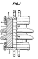
- Fig. 1 is a front elevational view, partly in cross section, of an embodiment of this invention;
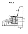
- Fig. 2 is a front elevational view, with portions broken away, partly in cross section, of another embodiment of this invention;
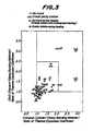
- Fig. 3 is a graph showing a thermal expansion coefficient ratio of the ZnO element to the glassy bonding material against a thermal expansion coefficient ratio of the insulator body to the glassy bonding material, in typical lightning arrestor insulators selected from experimental examples Nos. 1 to 32; and
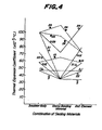
- Fig. 4 is a graph showing those coefficients in the absolute values.
- The present invention will be illustrated in more detail by the non-limitative examples below.
- In Fig. 1, the numeral 1 is an insulator body made of a ceramic, the
numeral 2 shows ZnO elements having voltage non-linear resistant characteristics and thenumeral 3 shows a glassy bonding material for integrally fixing theZnO elements 2 in a bore of the insulator body 1. TheZnO elements 2 comprise ZnO as a main component and contain a trace amount of additives such as Bi203, Sb203, CaO, MgO or the like as well as impurities, which are stacked successively with aconductive paste 4 such as silver paste intervening between them. Further, on both ends of the insulator body 1,fitments 5 such as a metallic flange, cap or the like are fixed with a cement 6, and the topmost and bottommost ends of theZnO elements 2 are electrically connected with the inner surfaces of thefitments 5. Further, as shown in Fig. 2, theZnO elements 2 may be fixed by theglassy bonding material 3 to the insulator body 1 of a suspension insulator. In this case, the topmost end of theZnO elements 2 is electrically connected with thecap fitment 8 via a fitment 7 and the bottommost end of theZnO elements 2 is also electrically connected with apin 10 via afitment 9. - As was described above, in the present invention, the
glassy bonding material 3 should have a thermal expansion coefficient smaller than the thermal expansion coefficients of both theZnO element 2 and the insulator body 1. Further, in order to prevent the ZnO elements from deterioration by heat during the sealing, aglassy bonding material 3 having a melting point at 350-520°C, more preferably 400-500°C, is employed. The reason why the thermal expansion coefficient of theglassy bonding material 3 should be smaller than the thermal expansion coefficients of theZnO element 2 and the insulator body 1 is, as appears from test data given hereinafter, to minimize to the possible utmost extent tensile stresses which develop in the end portion of theglassy bonding material 3 having lowest strength so that cracks starting from theglassy bonding material 3 may not initiate. Further, when the ratio of thermal expansion coefficient of theZnO element 2 to theglassy bonding material 3 is represented by A and that of the insulator body 1 to theglassy bonding material 3 is represented by B, it is preferred that A and B are in the ranges of 1 <A ≤2 and 1 <B≤2.5, respectively. This is because, if either A or B comes outside of the above range, cracks starting from theZnO element 2 or insulator body 1 tend to initiate. - Furthermore, since the ZnO element will deteriorate in its characteristics when a temperature of 500°C or higher is applied, it is desirable that as the glassy bonding material a low melting glass is used which is able to seal at a temperature not higher than 500°C. However, the
ZnO element 2 generally has a thermal expansion coefficient of about 40-80x10-7/°C and the insulator body 1 also has one of about 50-100×10-7/°C, while an ordinary low melting glass has a thermal expansion coefficient exceeding 100×10-7/°C, so that it is inadequate in the present invention to use the ordinary low melting glass as the glassy bonding material. Preferably, in the present invention, a PbO-B203 system glass having a composition such as to separate, during solidification, low expanding ceramic crystals such as ZrO.Si02, PbO.Ti02, β-eucryptite, cordierite and the like is used as the glassy bonding material that enables the sealing at a temperature lower than 500°C and that has a smaller thermal expansion coefficient than the ZnO element or the insulator body. Examples are shown in Table 1 below.
- Six blocks of ZnO element, each of 47 mm in outside diameter and 20 mm in length, which were bonded together with a conductive paste, were placed in an insulator body having an inside diameter of 51 mm, a trunk diameter of 81 mm, a shed diameter of 141 mm and a length of 120 mm. The insulator body in a heated condition at 490°C in an electric furnace was filled up with a glassy bonding material and then cooled down. Thus, various lightning arrestor insulators shown as Nos. 1-32 in Table 2 were obtained. With respect to those lightning arrestor insulators, crack initiating conditions were observed by means of a dyeing test. Then, a cooling and heating test by soaking alternately in warm water at 60°C and methylalcohol cooled with dry ice to -40°C, respectively for 4 hours, were repeated for 10 cycles and crack initiating conditions were observed by means of the dyeing test. The result is shown by marks o , A and x in Table 2. The mark o means no cracks observed, the mark A means cracks observed in a part of test-pieces and the mark x means cracks observed in all test-pieces.
- From the above experimental examples, typical ones were selected and plotted in Fig. 3 and Fig. 4. As is obvious from Fig. 3, good results are obtained in the ranges of 1 <A≤2 and 1 <B≤2.5.

- As is clear from the above explanation, by selecting a glassy bonding material having a thermal expansion coefficient smaller than the thermal expansion coefficients of the ZnO element and insulator body, crack initiation in the lightning arrestor insulator due to thermal stresses is prevented even in the case of rapid cooling or rapid heating during manufacture or voltage application, or strike the of a thunderbolt, and further an accident of fracture of the lightning arrestor insulator caused thereby is also prevented. Therefore, according to the present invention, insulators and electric equipment are not only protected from overcurrent in the case of thunderbolt strike, but also can maintain stable characteristics for a long period of time, so that troublesome work for maintenance and inspection can be saved. Thus, the present invention provides a lightning arrestor insulator which has eliminated or reduced former problems.
Claims (6)
Applications Claiming Priority (2)
| Application Number | Priority Date | Filing Date | Title |
|---|---|---|---|
| JP61282822A JPS63136424A (en) | 1986-11-27 | 1986-11-27 | Arresting insulator |
| JP282822/86 | 1986-11-27 |
Publications (2)
| Publication Number | Publication Date |
|---|---|
| EP0269195A1 EP0269195A1 (en) | 1988-06-01 |
| EP0269195B1 true EP0269195B1 (en) | 1990-01-10 |
Family
ID=17657532
Family Applications (1)
| Application Number | Title | Priority Date | Filing Date |
|---|---|---|---|
| EP87304924A Expired - Lifetime EP0269195B1 (en) | 1986-11-27 | 1987-06-03 | Lightning arrestor insulator |
Country Status (6)
| Country | Link |
|---|---|
| US (1) | US4796149A (en) |
| EP (1) | EP0269195B1 (en) |
| JP (1) | JPS63136424A (en) |
| KR (1) | KR910000622B1 (en) |
| CA (1) | CA1293293C (en) |
| DE (1) | DE3761404D1 (en) |
Families Citing this family (6)
| Publication number | Priority date | Publication date | Assignee | Title |
|---|---|---|---|---|
| IN171826B (en) * | 1988-03-23 | 1993-01-23 | Ngk Insulators Ltd | |
| EP0620566B1 (en) * | 1989-11-08 | 1996-07-17 | Matsushita Electric Industrial Co., Ltd. | A zinc oxide varistor, a method of preparing the same, and a crystallized glass composition for coating |
| JPH077613B2 (en) * | 1990-02-02 | 1995-01-30 | 東京電力株式会社 | Suspended lightning arrester |
| JPWO2005067114A1 (en) * | 2003-12-26 | 2007-12-20 | アレイプロトテック株式会社 | Lightning arrester and lightning arrester manufacturing method |
| CN100396632C (en) * | 2006-01-10 | 2008-06-25 | 陕西科技大学 | Preparation method of lead-free sealing glass for metal oxide lightning arrester |
| WO2011013776A1 (en) * | 2009-07-31 | 2011-02-03 | 旭硝子株式会社 | Sealing glass, sealing material and sealing material paste for semiconductor devices, and semiconductor device and process for production thereof |
Family Cites Families (9)
| Publication number | Priority date | Publication date | Assignee | Title |
|---|---|---|---|---|
| NL217651A (en) * | 1956-05-29 | 1900-01-01 | ||
| US3959543A (en) * | 1973-05-17 | 1976-05-25 | General Electric Company | Non-linear resistance surge arrester disc collar and glass composition thereof |
| US4335417A (en) * | 1978-09-05 | 1982-06-15 | General Electric Company | Heat sink thermal transfer system for zinc oxide varistors |
| US4223366A (en) * | 1978-11-15 | 1980-09-16 | Electric Power Research Institute, Inc. | Gapless surge arrester |
| JPS5827643B2 (en) * | 1979-07-13 | 1983-06-10 | 株式会社日立製作所 | Nonlinear resistor and its manufacturing method |
| US4463405A (en) * | 1981-02-19 | 1984-07-31 | Electric Power Research Institute, Inc. | Fail safe surge arrester |
| US4404614A (en) * | 1981-05-15 | 1983-09-13 | Electric Power Research Institute, Inc. | Surge arrester having a non-fragmenting outer housing |
| JPS5949178A (en) * | 1982-09-14 | 1984-03-21 | 中部電力株式会社 | Arrestor insulator |
| CH666575A5 (en) * | 1985-02-26 | 1988-07-29 | Bbc Brown Boveri & Cie | SURGE ARRESTERS. |
-
1986
- 1986-11-27 JP JP61282822A patent/JPS63136424A/en active Granted
-
1987
- 1987-05-27 US US07/054,789 patent/US4796149A/en not_active Expired - Fee Related
- 1987-06-03 EP EP87304924A patent/EP0269195B1/en not_active Expired - Lifetime
- 1987-06-03 DE DE8787304924T patent/DE3761404D1/en not_active Expired - Fee Related
- 1987-06-03 CA CA000538723A patent/CA1293293C/en not_active Expired - Fee Related
- 1987-06-05 KR KR1019870005744A patent/KR910000622B1/en not_active IP Right Cessation
Also Published As
| Publication number | Publication date |
|---|---|
| JPS63136424A (en) | 1988-06-08 |
| KR910000622B1 (en) | 1991-01-28 |
| JPH0255922B2 (en) | 1990-11-28 |
| KR880006722A (en) | 1988-07-23 |
| US4796149A (en) | 1989-01-03 |
| DE3761404D1 (en) | 1990-02-15 |
| CA1293293C (en) | 1991-12-17 |
| EP0269195A1 (en) | 1988-06-01 |
Similar Documents
| Publication | Publication Date | Title |
|---|---|---|
| US4128697A (en) | Hermetic glass-metal compression seal | |
| CA1320857C (en) | Optical fiber composite insulators and method for producing the same | |
| US4135038A (en) | Seal structure of ceramics and low expansion metallic material | |
| EP0788204B1 (en) | Ceramic insulator, its manufacture and spark plug incorporating it | |
| US4349635A (en) | Lower temperature glass and hermetic seal means and method | |
| US4310357A (en) | Low temperature sealing glass | |
| US4729010A (en) | Integrated circuit package with low-thermal expansion lead pieces | |
| US5262364A (en) | High thermal expansion, sealing glass | |
| EP0269195B1 (en) | Lightning arrestor insulator | |
| KR100254758B1 (en) | Cap and pin insulator and method for making thereof | |
| US4571660A (en) | Lightning arrester insulator | |
| US4199704A (en) | Alumina, calcia, baria, strontia sealing composition and article of manufacture | |
| US4621064A (en) | Low temperature sealing composition with synthetic zircon | |
| US4537863A (en) | Low temperature sealing composition | |
| US6922007B2 (en) | Spark plug with glaze coating | |
| EP0334647A1 (en) | Lightning arrestor insulator and method of producing the same | |
| US4349692A (en) | Glass hermetic seal | |
| US5821182A (en) | Hermetic sealing composition | |
| US3331913A (en) | Ceramic-glass sealing means for encapsulation of electrical devices | |
| US4309507A (en) | Glass and hermetic seal | |
| US4430664A (en) | Glass-moulded type semiconductor device | |
| US4146655A (en) | Method for encapsulating a semiconductor diode | |
| US4514207A (en) | Method for making terminal assembly for heart pacemaker | |
| US4518820A (en) | Terminal assembly for heart pacemakers | |
| JPS627154B2 (en) |
Legal Events
| Date | Code | Title | Description |
|---|---|---|---|
| PUAI | Public reference made under article 153(3) epc to a published international application that has entered the european phase |
Free format text: ORIGINAL CODE: 0009012 |
|
| AK | Designated contracting states |
Kind code of ref document: A1 Designated state(s): DE FR GB |
|
| 17P | Request for examination filed |
Effective date: 19880804 |
|
| 17Q | First examination report despatched |
Effective date: 19890307 |
|
| GRAA | (expected) grant |
Free format text: ORIGINAL CODE: 0009210 |
|
| AK | Designated contracting states |
Kind code of ref document: B1 Designated state(s): DE FR GB |
|
| REF | Corresponds to: |
Ref document number: 3761404 Country of ref document: DE Date of ref document: 19900215 |
|
| ET | Fr: translation filed | ||
| PLBE | No opposition filed within time limit |
Free format text: ORIGINAL CODE: 0009261 |
|
| STAA | Information on the status of an ep patent application or granted ep patent |
Free format text: STATUS: NO OPPOSITION FILED WITHIN TIME LIMIT |
|
| 26N | No opposition filed | ||
| PGFP | Annual fee paid to national office [announced via postgrant information from national office to epo] |
Ref country code: GB Payment date: 19980522 Year of fee payment: 12 |
|
| PGFP | Annual fee paid to national office [announced via postgrant information from national office to epo] |
Ref country code: FR Payment date: 19980617 Year of fee payment: 12 |
|
| PGFP | Annual fee paid to national office [announced via postgrant information from national office to epo] |
Ref country code: DE Payment date: 19980620 Year of fee payment: 12 |
|
| PG25 | Lapsed in a contracting state [announced via postgrant information from national office to epo] |
Ref country code: GB Free format text: LAPSE BECAUSE OF NON-PAYMENT OF DUE FEES Effective date: 19990603 |
|
| PG25 | Lapsed in a contracting state [announced via postgrant information from national office to epo] |
Ref country code: FR Free format text: THE PATENT HAS BEEN ANNULLED BY A DECISION OF A NATIONAL AUTHORITY Effective date: 19990630 |
|
| GBPC | Gb: european patent ceased through non-payment of renewal fee |
Effective date: 19990603 |
|
| PG25 | Lapsed in a contracting state [announced via postgrant information from national office to epo] |
Ref country code: DE Free format text: LAPSE BECAUSE OF NON-PAYMENT OF DUE FEES Effective date: 20000503 |
|
| REG | Reference to a national code |
Ref country code: FR Ref legal event code: ST |