EP0268684B2 - Monitoring system for maintenance of car - Google Patents
Monitoring system for maintenance of car Download PDFInfo
- Publication number
- EP0268684B2 EP0268684B2 EP87902743A EP87902743A EP0268684B2 EP 0268684 B2 EP0268684 B2 EP 0268684B2 EP 87902743 A EP87902743 A EP 87902743A EP 87902743 A EP87902743 A EP 87902743A EP 0268684 B2 EP0268684 B2 EP 0268684B2
- Authority
- EP
- European Patent Office
- Prior art keywords
- time
- car
- replacement
- signal
- display
- Prior art date
- Legal status (The legal status is an assumption and is not a legal conclusion. Google has not performed a legal analysis and makes no representation as to the accuracy of the status listed.)
- Expired - Lifetime
Links
- 238000012423 maintenance Methods 0.000 title claims abstract description 17
- 238000012544 monitoring process Methods 0.000 title abstract description 4
- 230000000737 periodic effect Effects 0.000 claims description 8
- 230000001960 triggered effect Effects 0.000 claims 1
- 238000000034 method Methods 0.000 description 5
- 239000003921 oil Substances 0.000 description 4
- 238000010586 diagram Methods 0.000 description 2
- 230000005540 biological transmission Effects 0.000 description 1
- 238000010276 construction Methods 0.000 description 1
- 238000005260 corrosion Methods 0.000 description 1
- 230000007797 corrosion Effects 0.000 description 1
- 230000001419 dependent effect Effects 0.000 description 1
- 230000000881 depressing effect Effects 0.000 description 1
- 230000000994 depressogenic effect Effects 0.000 description 1
- 238000001514 detection method Methods 0.000 description 1
- 239000012530 fluid Substances 0.000 description 1
- 239000000446 fuel Substances 0.000 description 1
- 239000004519 grease Substances 0.000 description 1
- 239000010705 motor oil Substances 0.000 description 1
- 238000011144 upstream manufacturing Methods 0.000 description 1
Images


Classifications
-
- G—PHYSICS
- G07—CHECKING-DEVICES
- G07C—TIME OR ATTENDANCE REGISTERS; REGISTERING OR INDICATING THE WORKING OF MACHINES; GENERATING RANDOM NUMBERS; VOTING OR LOTTERY APPARATUS; ARRANGEMENTS, SYSTEMS OR APPARATUS FOR CHECKING NOT PROVIDED FOR ELSEWHERE
- G07C5/00—Registering or indicating the working of vehicles
- G07C5/006—Indicating maintenance
-
- F—MECHANICAL ENGINEERING; LIGHTING; HEATING; WEAPONS; BLASTING
- F01—MACHINES OR ENGINES IN GENERAL; ENGINE PLANTS IN GENERAL; STEAM ENGINES
- F01M—LUBRICATING OF MACHINES OR ENGINES IN GENERAL; LUBRICATING INTERNAL COMBUSTION ENGINES; CRANKCASE VENTILATING
- F01M11/00—Component parts, details or accessories, not provided for in, or of interest apart from, groups F01M1/00 - F01M9/00
- F01M11/10—Indicating devices; Other safety devices
-
- F—MECHANICAL ENGINEERING; LIGHTING; HEATING; WEAPONS; BLASTING
- F02—COMBUSTION ENGINES; HOT-GAS OR COMBUSTION-PRODUCT ENGINE PLANTS
- F02B—INTERNAL-COMBUSTION PISTON ENGINES; COMBUSTION ENGINES IN GENERAL
- F02B77/00—Component parts, details or accessories, not otherwise provided for
- F02B77/08—Safety, indicating, or supervising devices
- F02B77/083—Safety, indicating, or supervising devices relating to maintenance, e.g. diagnostic device
-
- F—MECHANICAL ENGINEERING; LIGHTING; HEATING; WEAPONS; BLASTING
- F16—ENGINEERING ELEMENTS AND UNITS; GENERAL MEASURES FOR PRODUCING AND MAINTAINING EFFECTIVE FUNCTIONING OF MACHINES OR INSTALLATIONS; THERMAL INSULATION IN GENERAL
- F16N—LUBRICATING
- F16N2260/00—Fail safe
- F16N2260/02—Indicating
- F16N2260/18—Indicating necessity of changing oil
Definitions
- the present invention relates to a monitoring system for control and maintenance of cars,and is particularly concerned with a monitor system for control and maintenance of a car, indicating change of objects such as oil, filter and the like at each part of the car, and further indicating supply of grease and fuel.
- a display apparatus for automotive vehicles which is capable to present on a display the time in hours and minutes and upon command other functions such as miles before service is required and days before service is required.
- the apparatus includes at least one logic integrated circuit for providing required frequency division of various inputs, a storage for accumulating information received from the integrated circuit and for retaining the information over a period of time even though power to the circuit is interrupted, a power supply and a display for displaying information on demand.
- a timer for measuring accumulated operating hours of a car is provided, a time measured by the timer and a periodic time for changing each of objects such as oil, filter and the like which is specified in an instruction manual are compared with each other, and when the measured time reaches the periodic time, the particular object is subjected to change.
- the aforementioned objects to change are rather numerous, and the periodic time is dependent on each of the objects to be changed. Threfore, if the change is left solely to a decision of an operator or controller of the car, then they will be overburdened to miss sometimes an opportunity to change the objects.
- the invention has been made in view of the above circumstances, and hence a primary object of the invention is to provide a monitor system for control and maintenance of a car which is capable positively of indicating maintenance informations about objects to be changed to an operator or controller of the car.
- Another object of the invention is to provide a monitor system for control and maintenance of a car, wherein objects to be changed, even though those are numerous in number, can positively be changed by an operator or controller of the car at their respective optimum times. This is achieved by the features of claim 1
- the construction is such that when accumulated operating hours of a car measured by the time measuring means reach a predetermined periodic time whereat any of a plurality of objects is to be changed, an indication for changing the particular object is given on a display.
- Fig. 1 is a block diagram representing one embodiment of a monitor system for control and maintenance of a car relating to the invention.
- the system comprises an engine operation detector 1, a multi-display 2, time check switches 3, 4, a set switch 5, a cancel switch 6, filter loading sensors 7, 8, 9, a printer 10, an 1/0 port 11, a central processing unit (CPU) 12, ROM 13, RAM 14 and EEPROM 15.
- CPU central processing unit
- the engine operation detector 1 is a unit for detecting whether or not an engine operates, consists, for example, of an oil pressure sensor for detecting an engine oil pressure, and generates a signal "1 " at the time when operating the engine.
- the multi-display 2 has display lamps L o to Lg for respectively indicating an change of objects Ao to As to be changed such as oil, filter and the like, a display lamp L 1 o for indicating a time in four digits and so forth.
- objects Ao to As to be changed and their respective time intervals for change are given in the following Table 1.
- Each of the filter loading sensors 7, 8, 9 detects a loading of the aforementioned corrosion resistor A 7 , transmission filter As and hydraulic fluid filter Ag, the loading is then detected on a differential pressure between upstream side and downstream side of the filter which may arise due to a pressure loss by, for example, filter pass, and the signal "1 " is generated at the time of this detection.
- ROM 13 stores maintenance informations (time interval for change) programmed beforehand for the objects Ao to As to be changed and others therein, RAM 14 stores temporarily results obtained through arithmetic operation by CPU 12 to be described hereinafter, and EEPROM 15 stores past maintenance informations therein.
- CPU 12 Uppon inputting the signal "1" from the engine operation detector 1 through the 1/0 port 11, CPU 12 starts the following process:
- Step 104 Whether or not the engine is operating is discriminated in Step 104, and when operating, the process goes forward to Step 105.
- Step 105 Whether or not T is one hour or over is discriminated in Step 105, and when it is less than one hour, the process returns to Step 102 and repeats Steps 102 to 105.
- T exceeds one hour, one hour is subtracted from the exchange time interval Hn (Step 106), and whether or not each Hn is 0 or belowo is discriminated (Step 107).
- Step 109 a display lamp Ln indicating the object to be exchanged having been 0 or below 0 is lighted, and a residual time (0 or minus time) is indicated flickeringly on a display lamp L io (Step 109).
- Step 110 the aforementioned state is stored, that is, the display lamp Ln is kept lighting and flickering for the residual time, and the process returns to Step 102 through Step 108.
- the time check switch 3 is used for indicating a residual time for each of the objects As to As on the display lamp L 10 .
- the residual time becomes 0 or below 0 the display lamp Ln is lighted, and the residual time is also indicated flickeringly thereon.
- Such display indicates a change of the object to be changed, therefore a controller of the car will lose no time to renew the object which is so indicated thereon.
- the set switch 5 (Fig. 1 and Fig. 2) is depressed for several seconds according to a change time interval of the object, now changed, indicated by depressing the time check switch before the engine restarts up.
- CPU 12 recognizes the object indicated for change as having been renewed, and a data indicating the next change time interval of the object is read out of ROM 13. Thus, the lighted display lamp goes out, and a new change time interval is indicated on the display lamp Lio.
- the cancel switch 6 functions where the set switch 5 is operated erroneously, thereby reverting to the state before the set switch 5 was operated. Further, when the filter loading sensors 7, 8, 9 detect loading, CPU 12 flickers the corresponding display lamp, thereby advising an operator or controller of car thereof. Then, past maintenance informations on hours for changing each object or the like is written in EEPROM 15, and thus the maintenance informations can be printed out to the printer 10 as occasion demands.
Landscapes
- Engineering & Computer Science (AREA)
- Mechanical Engineering (AREA)
- General Engineering & Computer Science (AREA)
- Chemical & Material Sciences (AREA)
- Combustion & Propulsion (AREA)
- Physics & Mathematics (AREA)
- General Physics & Mathematics (AREA)
- Vehicle Cleaning, Maintenance, Repair, Refitting, And Outriggers (AREA)
- Time Recorders, Dirve Recorders, Access Control (AREA)
Abstract
Description
- The present invention relates to a monitoring system for control and maintenance of cars,and is particularly concerned with a monitor system for control and maintenance of a car, indicating change of objects such as oil, filter and the like at each part of the car, and further indicating supply of grease and fuel.
- In the US 4,031,363 a display apparatus for automotive vehicles is described which is capable to present on a display the time in hours and minutes and upon command other functions such as miles before service is required and days before service is required. The apparatus includes at least one logic integrated circuit for providing required frequency division of various inputs, a storage for accumulating information received from the integrated circuit and for retaining the information over a period of time even though power to the circuit is interrupted, a power supply and a display for displaying information on demand.
- Heretofore, for maintenance and control of a car, a timer for measuring accumulated operating hours of a car is provided, a time measured by the timer and a periodic time for changing each of objects such as oil, filter and the like which is specified in an instruction manual are compared with each other, and when the measured time reaches the periodic time, the particular object is subjected to change.
- However, the aforementioned objects to change are rather numerous, and the periodic time is dependent on each of the objects to be changed. Threfore, if the change is left solely to a decision of an operator or controller of the car, then they will be overburdened to miss sometimes an opportunity to change the objects.
- The invention has been made in view of the above circumstances, and hence a primary object of the invention is to provide a monitor system for control and maintenance of a car which is capable positively of indicating maintenance informations about objects to be changed to an operator or controller of the car.
- Another object of the invention is to provide a monitor system for control and maintenance of a car, wherein objects to be changed, even though those are numerous in number, can positively be changed by an operator or controller of the car at their respective optimum times. This is achieved by the features of
claim 1 - That is, in the monitor system for control and maintenance of a car according to the invention, the construction is such that when accumulated operating hours of a car measured by the time measuring means reach a predetermined periodic time whereat any of a plurality of objects is to be changed, an indication for changing the particular object is given on a display.
-
- Fig. 1 is a block diagram representing one embodiment of a monitor system for control and maintenance of a car relating to the invention;
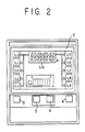
- Fig. 2 is a font view showing details of a multi-display part shown in Fig. 1; and
- Fig 3 is a flowchart for illustrating an operation of CPU shown in Fig. 1.
- The invention will now be described in detail with reference to the accompanying drawings.
- Fig. 1 is a block diagram representing one embodiment of a monitor system for control and maintenance of a car relating to the invention.
- The system comprises an
engine operation detector 1, a multi-display 2, time check switches 3, 4, aset switch 5, acancel switch 6,filter loading sensors printer 10, an 1/0port 11, a central processing unit (CPU) 12,ROM 13,RAM 14 andEEPROM 15. - The
engine operation detector 1 is a unit for detecting whether or not an engine operates, consists, for example, of an oil pressure sensor for detecting an engine oil pressure, and generates a signal "1 " at the time when operating the engine. - As shown in Fig. 2, for example, the multi-display 2 has display lamps Lo to Lg for respectively indicating an change of objects Ao to As to be changed such as oil, filter and the like, a display lamp L1 o for indicating a time in four digits and so forth. Now, examples of the objects Ao to As to be changed and their respective time intervals for change are given in the following Table 1.

- Each of the
filter loading sensors -
ROM 13 stores maintenance informations (time interval for change) programmed beforehand for the objects Ao to As to be changed and others therein,RAM 14 stores temporarily results obtained through arithmetic operation byCPU 12 to be described hereinafter, and EEPROM 15 stores past maintenance informations therein. - Next, an operation of
CPU 12 will be described with reference to a flowchart given in Fig. 3. - Uppon inputting the signal "1" from the
engine operation detector 1 through the 1/0port 11,CPU 12 starts the following process: - First, a change time interval Hn of an object An (n = 0-9) to be changed is read, a surplus engine operating time To less than one hour is read (Step 100), the read To is then specified as T, and t is reset to 0 (Step 101).
- Next, whether or not one second passed, or t = 1 sec. is decided (Step 102), and when one second passed, one second is added to the aforementioned T, and t is reset to 0 (Step 103).
- Whether or not the engine is operating is discriminated in
Step 104, and when operating, the process goes forward toStep 105. Whether or not T is one hour or over is discriminated inStep 105, and when it is less than one hour, the process returns toStep 102 and repeatsSteps 102 to 105. When T exceeds one hour, one hour is subtracted from the exchange time interval Hn (Step 106), and whether or not each Hn is 0 or belowo is discriminated (Step 107). - If Hn is not 0 or belowo, then T is reset to 0 (Step 108), and the process returns again to
Step 102. Thus, each Hn is subtracted one hour by one. - Then, when any one or a plurality of Hn become 0 or below 0, a display lamp Ln indicating the object to be exchanged having been 0 or below 0 is lighted, and a residual time (0 or minus time) is indicated flickeringly on a display lamp Lio(Step 109). In
Step 110 the aforementioned state is stored, that is, the display lamp Ln is kept lighting and flickering for the residual time, and the process returns toStep 102 throughStep 108. - Then, when the engine stops, the change time interval Hn subtracted one hour by one successively is stored, and the surplus time T less than one hour is stored as To (Step 111). When the engine comes into operation again, these Hn and To are read in
Step 100. - Meanwhile, the time check switch 3 shown in Fig. 1 and Fig. 2 is that for checking a residual time of the objects Ao to A4 the objects are then changed as Ao- A1 → A2 - A3 - A4 → A5 → A6 ...... according to a switch operation, and a time (Hn shown in Fig. 3) of the corresponding object An is displayed on the display lamp Llo. Then, in this case, a bar display is given on the display lamp Ln corresponding to the time- displayed object to be changed.
- Similarly, the time check switch 3 is used for indicating a residual time for each of the objects As to As on the display lamp L10.
- Described next is the case where the residual time becomes 0 or below 0 the display lamp Ln is lighted, and the residual time is also indicated flickeringly thereon.
- Such display indicates a change of the object to be changed, therefore a controller of the car will lose no time to renew the object which is so indicated thereon. Whenever the change is over, the set switch 5 (Fig. 1 and Fig. 2) is depressed for several seconds according to a change time interval of the object, now changed, indicated by depressing the time check switch before the engine restarts up.
- According to the aforementioned switch operation,
CPU 12 recognizes the object indicated for change as having been renewed, and a data indicating the next change time interval of the object is read out ofROM 13. Thus, the lighted display lamp goes out, and a new change time interval is indicated on the display lamp Lio. - Then, the
cancel switch 6 functions where theset switch 5 is operated erroneously, thereby reverting to the state before theset switch 5 was operated. Further, when thefilter loading sensors CPU 12 flickers the corresponding display lamp, thereby advising an operator or controller of car thereof. Then, past maintenance informations on hours for changing each object or the like is written in EEPROM 15, and thus the maintenance informations can be printed out to theprinter 10 as occasion demands.
Claims (2)
characterized in that
Applications Claiming Priority (3)
| Application Number | Priority Date | Filing Date | Title |
|---|---|---|---|
| JP91757/86 | 1986-04-21 | ||
| JP61091757A JP2603067B2 (en) | 1986-04-21 | 1986-04-21 | Monitor system for vehicle maintenance management |
| PCT/JP1987/000254 WO1987006648A1 (en) | 1986-04-21 | 1987-04-21 | Monitoring system for maintenance of car |
Publications (4)
| Publication Number | Publication Date |
|---|---|
| EP0268684A1 EP0268684A1 (en) | 1988-06-01 |
| EP0268684A4 EP0268684A4 (en) | 1988-09-28 |
| EP0268684B1 EP0268684B1 (en) | 1991-09-04 |
| EP0268684B2 true EP0268684B2 (en) | 1994-09-07 |
Family
ID=14035410
Family Applications (1)
| Application Number | Title | Priority Date | Filing Date |
|---|---|---|---|
| EP87902743A Expired - Lifetime EP0268684B2 (en) | 1986-04-21 | 1987-04-21 | Monitoring system for maintenance of car |
Country Status (5)
| Country | Link |
|---|---|
| EP (1) | EP0268684B2 (en) |
| JP (1) | JP2603067B2 (en) |
| AU (2) | AU7287187A (en) |
| DE (1) | DE3772716D1 (en) |
| WO (1) | WO1987006648A1 (en) |
Families Citing this family (6)
| Publication number | Priority date | Publication date | Assignee | Title |
|---|---|---|---|---|
| FR2629238B1 (en) * | 1988-03-22 | 1990-11-23 | Sgs Thomson Microelectronics | ELECTRONIC VEHICLE MAINTENANCE SYSTEM |
| ES2011131A6 (en) * | 1989-04-18 | 1989-12-16 | Kanshin Nikolai Nikolaevich | Stem for surgical suture apparatus. |
| FR2663144A1 (en) * | 1990-06-12 | 1991-12-13 | Pastore Solange | Process and device for monitoring maintenance of mechanical elements |
| FR2687255B1 (en) * | 1992-02-07 | 1994-03-25 | Renault Regie Nale Usines | METHOD FOR ESTIMATING THE WEAR OF A CANDLE. |
| US6172602B1 (en) * | 1999-03-22 | 2001-01-09 | Detroit Diesel Corporation | Maintenance alert system for heavy-duty trucks |
| DE102006011886A1 (en) * | 2006-03-15 | 2007-09-20 | Bayerische Motoren Werke Ag | Device and method for determining the wear of a spark plug of an internal combustion engine |
Family Cites Families (13)
| Publication number | Priority date | Publication date | Assignee | Title |
|---|---|---|---|---|
| US4031363A (en) * | 1976-05-17 | 1977-06-21 | General Time Corporation | Display apparatus for automotive vehicles |
| US4053868A (en) * | 1976-12-27 | 1977-10-11 | Caterpillar Tractor Co. | Vehicle system monitor |
| JPS556440U (en) * | 1978-06-26 | 1980-01-17 | ||
| JPS5621938A (en) * | 1979-07-27 | 1981-02-28 | Hino Motors Ltd | Alarm aparatus for automobile |
| DE3110774A1 (en) * | 1981-03-19 | 1982-10-14 | Daimler-Benz Ag, 7000 Stuttgart | "METHOD FOR DETERMINING MAINTENANCE AND CARE INTERVALS" |
| JPS6044490B2 (en) * | 1981-07-29 | 1985-10-03 | 日産自動車株式会社 | Engine oil change instruction device |
| DE3134121A1 (en) * | 1981-08-28 | 1983-03-17 | Vdo Adolf Schindling Ag, 6000 Frankfurt | Device for indicating the servicing time of a motor vehicle |
| FR2515261B1 (en) * | 1981-10-28 | 1987-05-29 | Belou Michel | APPARATUS FOR MONITORING AN EXPLOSION ENGINE, ESPECIALLY ON BOARD A VEHICLE |
| JPS58118211U (en) * | 1982-02-04 | 1983-08-12 | ヤンマーディーゼル株式会社 | Warning device for oil changes, etc. |
| JPS58118210U (en) * | 1982-02-04 | 1983-08-12 | ヤンマーディーゼル株式会社 | Warning device for oil changes, etc. |
| US4612623A (en) * | 1984-08-03 | 1986-09-16 | Maintenance Technology, Inc. | Tamper-resistant, running time maintenance monitor with individualized maintenance message and method |
| JPH0138250Y2 (en) * | 1984-08-30 | 1989-11-16 | ||
| GB8422791D0 (en) * | 1984-09-08 | 1984-10-17 | Univ Belfast | Tenderizing of meat |
-
1986
- 1986-04-21 JP JP61091757A patent/JP2603067B2/en not_active Expired - Fee Related
-
1987
- 1987-04-21 WO PCT/JP1987/000254 patent/WO1987006648A1/en not_active Ceased
- 1987-04-21 AU AU72871/87A patent/AU7287187A/en not_active Abandoned
- 1987-04-21 EP EP87902743A patent/EP0268684B2/en not_active Expired - Lifetime
- 1987-04-21 DE DE8787902743T patent/DE3772716D1/en not_active Expired - Fee Related
-
1991
- 1991-02-27 AU AU71979/91A patent/AU631726B2/en not_active Ceased
Also Published As
| Publication number | Publication date |
|---|---|
| EP0268684A4 (en) | 1988-09-28 |
| AU7197991A (en) | 1991-05-09 |
| WO1987006648A1 (en) | 1987-11-05 |
| EP0268684B1 (en) | 1991-09-04 |
| AU631726B2 (en) | 1992-12-03 |
| JP2603067B2 (en) | 1997-04-23 |
| EP0268684A1 (en) | 1988-06-01 |
| DE3772716D1 (en) | 1991-10-10 |
| JPS62247938A (en) | 1987-10-29 |
| AU7287187A (en) | 1987-11-24 |
Similar Documents
| Publication | Publication Date | Title |
|---|---|---|
| CA2088270C (en) | Adaptive vehicle display | |
| US5654902A (en) | Recyclable component with data storage for storing information for examining the component and product including such a component | |
| US5831540A (en) | Control system for loading docks | |
| US4926331A (en) | Truck operation monitoring system | |
| US5450321A (en) | Interactive dynamic realtime management system for powered vehicles | |
| US5479350A (en) | Exhaust gas temperature indicator for a gas turbine engine | |
| US8078355B2 (en) | Failure-diagnosis information collection system | |
| KR100288748B1 (en) | A monitering system and method of a railway vehicle | |
| EP0174601A1 (en) | Oil degradation warning system | |
| US5592395A (en) | Method and apparatus for determining and extending a change interval for an operating fluid of a unit | |
| AU3867900A (en) | Maintenance alert system for heavy-duty trucks | |
| CN113892066A (en) | Information processing system, gateway, server, and information processing method | |
| EP0268684B1 (en) | Monitoring system for maintenance of car | |
| US5339339A (en) | Process for carrying out an inspection round of nuclear installations | |
| US5521844A (en) | Printing press monitoring and advising system | |
| EP0602707A2 (en) | Transmission oil monitoring system | |
| DE29606594U1 (en) | Monitoring system for liquid gas containers, compressed gas containers or liquid gas or compressed gas pipelines | |
| US6087929A (en) | Indication device | |
| JP2852965B2 (en) | Refueling management system | |
| JPH08108983A (en) | Brake testing device | |
| JPH01288991A (en) | Maintenance monitor device | |
| JPH06107388A (en) | Elevator operation data collection device | |
| JP3074198B2 (en) | Equipment data management device | |
| JPH1083495A (en) | Water meter | |
| GB2031164A (en) | Improvements in and relating to an automotive automatic diagnostics system and apparatus therefor |
Legal Events
| Date | Code | Title | Description |
|---|---|---|---|
| PUAI | Public reference made under article 153(3) epc to a published international application that has entered the european phase |
Free format text: ORIGINAL CODE: 0009012 |
|
| AK | Designated contracting states |
Kind code of ref document: A1 Designated state(s): DE GB |
|
| 17P | Request for examination filed |
Effective date: 19880416 |
|
| A4 | Supplementary search report drawn up and despatched |
Effective date: 19880928 |
|
| 17Q | First examination report despatched |
Effective date: 19900201 |
|
| GRAA | (expected) grant |
Free format text: ORIGINAL CODE: 0009210 |
|
| AK | Designated contracting states |
Kind code of ref document: B1 Designated state(s): DE GB |
|
| REF | Corresponds to: |
Ref document number: 3772716 Country of ref document: DE Date of ref document: 19911010 |
|
| PLBI | Opposition filed |
Free format text: ORIGINAL CODE: 0009260 |
|
| 26 | Opposition filed |
Opponent name: HELLA KG HUECK & CO. Effective date: 19920527 |
|
| PUAA | Information related to the publication of a b2 document modified |
Free format text: ORIGINAL CODE: 0009299PMAP |
|
| PUAH | Patent maintained in amended form |
Free format text: ORIGINAL CODE: 0009272 |
|
| STAA | Information on the status of an ep patent application or granted ep patent |
Free format text: STATUS: PATENT MAINTAINED AS AMENDED |
|
| 27A | Patent maintained in amended form |
Effective date: 19940907 |
|
| AK | Designated contracting states |
Kind code of ref document: B2 Designated state(s): GB |
|
| R27A | Patent maintained in amended form (corrected) |
Effective date: 19940907 |
|
| PGFP | Annual fee paid to national office [announced via postgrant information from national office to epo] |
Ref country code: DE Payment date: 19970428 Year of fee payment: 11 |
|
| PGFP | Annual fee paid to national office [announced via postgrant information from national office to epo] |
Ref country code: GB Payment date: 19980414 Year of fee payment: 12 |
|
| PG25 | Lapsed in a contracting state [announced via postgrant information from national office to epo] |
Ref country code: DE Free format text: LAPSE BECAUSE OF NON-PAYMENT OF DUE FEES Effective date: 19990202 |
|
| PG25 | Lapsed in a contracting state [announced via postgrant information from national office to epo] |
Ref country code: GB Free format text: LAPSE BECAUSE OF NON-PAYMENT OF DUE FEES Effective date: 19990421 |
|
| GBPC | Gb: european patent ceased through non-payment of renewal fee |
Effective date: 19990421 |