EP0268620B2 - Projectable passive liquid crystal display - Google Patents
Projectable passive liquid crystal display Download PDFInfo
- Publication number
- EP0268620B2 EP0268620B2 EP19870903255 EP87903255A EP0268620B2 EP 0268620 B2 EP0268620 B2 EP 0268620B2 EP 19870903255 EP19870903255 EP 19870903255 EP 87903255 A EP87903255 A EP 87903255A EP 0268620 B2 EP0268620 B2 EP 0268620B2
- Authority
- EP
- European Patent Office
- Prior art keywords
- display panel
- housing
- display
- display unit
- pixels
- Prior art date
- Legal status (The legal status is an assumption and is not a legal conclusion. Google has not performed a legal analysis and makes no representation as to the accuracy of the status listed.)
- Expired - Lifetime
Links
Images

Classifications
-
- G—PHYSICS
- G02—OPTICS
- G02F—OPTICAL DEVICES OR ARRANGEMENTS FOR THE CONTROL OF LIGHT BY MODIFICATION OF THE OPTICAL PROPERTIES OF THE MEDIA OF THE ELEMENTS INVOLVED THEREIN; NON-LINEAR OPTICS; FREQUENCY-CHANGING OF LIGHT; OPTICAL LOGIC ELEMENTS; OPTICAL ANALOGUE/DIGITAL CONVERTERS
- G02F1/00—Devices or arrangements for the control of the intensity, colour, phase, polarisation or direction of light arriving from an independent light source, e.g. switching, gating or modulating; Non-linear optics
- G02F1/01—Devices or arrangements for the control of the intensity, colour, phase, polarisation or direction of light arriving from an independent light source, e.g. switching, gating or modulating; Non-linear optics for the control of the intensity, phase, polarisation or colour
- G02F1/13—Devices or arrangements for the control of the intensity, colour, phase, polarisation or direction of light arriving from an independent light source, e.g. switching, gating or modulating; Non-linear optics for the control of the intensity, phase, polarisation or colour based on liquid crystals, e.g. single liquid crystal display cells
- G02F1/133—Constructional arrangements; Operation of liquid crystal cells; Circuit arrangements
- G02F1/1333—Constructional arrangements; Manufacturing methods
- G02F1/13338—Input devices, e.g. touch panels
-
- G—PHYSICS
- G09—EDUCATION; CRYPTOGRAPHY; DISPLAY; ADVERTISING; SEALS
- G09F—DISPLAYING; ADVERTISING; SIGNS; LABELS OR NAME-PLATES; SEALS
- G09F13/00—Illuminated signs; Luminous advertising
- G09F13/04—Signs, boards or panels, illuminated from behind the insignia
- G09F13/0409—Arrangements for homogeneous illumination of the display surface, e.g. using a layer having a non-uniform transparency
Definitions
- the invention relates to a projectable, passive liquid crystal matrix display device with a display unit, to which an electronic control unit is assigned and on which individual planar elements, so-called pixels, which are connected to the control unit via conductor tracks, can be switched between a translucent and a light-absorbing state , and with two polarization filters, one of which is arranged in the light path in front, the other in the light path behind the display unit.
- the known display devices of this type are flat units and are therefore also referred to as flat screen in English. They can be placed on the projection surface (object level) of an overhead projector, with the display unit in the object level. In this way, the information in the display unit can be mapped onto the image plane (screen, projection surface) in the form of, for example, writing, formulas, a drawing, surface elements or the like.
- liquid crystal displays offer a number of advantages that distinguish them from other displays, such as low supply voltage, no flicker, low weight, flat overall height, transparency, freedom from radiation exposure. Use for projection devices is therefore desirable.
- the object of the invention is to further develop the liquid crystal display devices of the type mentioned at the outset, in particular liquid crystal matrix displays, in such a way that they are suitable for projection and in particular withstand the thermal loads which are present on the projection table of an overhead projector.
- the polarization filters cannot directly pass on the heat generated in them to the display unit.
- the polarization filters can be replaced independently of the display unit.
- a space is created between the display unit and the respective polarization filter, through which the air flow serving for cooling can flow. Since in the display devices, which are usually operated in a horizontal state, the heat practically does not flow away through convective air currents, constant cooling is achieved via the forced air flow generated by a fan. This cooling not only benefits the actual display unit, but also extends the life of the polarizing films.
- the display device is located in a flat housing.
- the display unit itself has approximately the size of the projection area of overhead projectors, for example DIN A4 or A5 format.
- the housing is only a few centimeters high, for example 40 mm. Accordingly, the distance between the display unit and the polarization foils arranged above and below it is only a few millimeters, for example 15 to 20 mm.
- the pressure side of the fan located in the housing is connected directly to the outside world via outlet openings and the air is sucked in through the housing via various inlet openings.
- the air flow can be controlled specifically via the special arrangement of the inlet openings, via special air baffles and the like.
- the center of the polarization filters or the display unit is cooled more, and there is also a higher heat.
- the areas of the filter or display unit located at the rear in the airway are supplied with fresh air which is fed in laterally and are not only cooled with air which has already been heated by contact with other points.
- the polarization filters it is proposed to connect at least one of the polarization filters to a pane made of glass or plastic and to fasten this pane in a detachable and replaceable manner to the housing.
- a frame is particularly suitable for this purpose, into which the pane coated on the inside with the polarizing film can be inserted.
- the fixation can be done by snapping springs, quick-release screws, unscrewable feet or the like.
- the decisive factor here is that the pane is placed on the housing from the outside, so that the casing does not have to be opened to remove the pane including the polarizing film.
- a polarization filter rotatably on the housing.
- the carrier plates for the polarizing films and the actual display unit with a UV protection filter, in particular a vapor-deposited or glued layer. This avoids that the greedy UV component leads to chemical processes and other damaging influences.
- An anti-reflective layer or film on the surfaces of the polarization filters, plates, the display unit etc. is also advantageous, as a result of which the light reflection within the multilayer unit and thus the loss of light are reduced.
- the invention relates to an improvement of the display unit itself.
- a single-layer display unit all pixels are in the same plane.
- the individual pixels must necessarily be electrically isolated from one another. This inevitably results in empty spaces between the individual pixels.
- the display unit is thus designed such that when viewed vertically on the display surface, the pixels of the various layers complement one another to form a closed surface.
- the described staggered combination of two and more layers (information levels) to form a total area makes it possible to avoid the distances between the pixels of a character or a representation that generally occur in liquid crystal displays in any operating mode.
- these are also arranged at a distance from the display unit and are located in the cooling air flow.
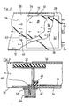
- the display device according to FIG. 1 is located on an upper, horizontal plate 20 with a glass insert 22 of an overhead projector, not shown here.
- the display unit has a flat, essentially cubic housing, of which the right side wall 24, the left side wall 26, the upper wall 28 and the lower wall 30 are shown in the figure.
- Square glass plates 32, 34 are each inserted flush with the surface in the upper and lower walls 28, 30. They have on their inner sides an approximately uniform-sized polarization filter 36 and 38, which is glued to them over the surface. Both glass plates 32, 34, including the polarization filter 36 and 38 they carry, can be mounted and dismounted quickly and without opening the housing. This is shown in FIG. 1 for the lower glass plate 34; reference is also made to FIG. 3.
- the glass plate 34 is supported towards the inside of the housing by a frame-shaped, circumferential, L-shaped flange 40.
- a likewise L-shaped, elastic, frame-shaped part 42 ensures flexible storage.
- the glass plate 34 is pressed against the flange 40 by disks 46 connected to cylindrical feet 44, a total of four feet 44 are provided. There is an internal thread in them.
- a screw 48 is fixedly connected, for example glued, to the housing, which protrudes outward with its threaded pin and engages in the internal thread of the associated foot 44. If the four feet 44 are unscrewed, the glass plate 34 including the associated polarization filter 38 can be removed.
- a plurality of holes 56 are provided in the right side wall 24, through which air flows into the interior of the housing (arrows 58). This air flows through the channel-like gaps above and below the display unit 50. It preferably sweeps over the lower polarization filter 38, in which the greatest light absorption and thus the greatest heat development takes place.
- the holes 56 are further arranged so that the central region of the polarization filters 36, 38 is preferably cooled.
- outlet holes 66 In the vicinity of the left side wall 26 there are a large number of outlet holes 66. Immediately in front of them is a fan 68 of a blower (not otherwise shown) which drives the air movements described. In an alternative (not shown), the outlet holes can also be arranged in the lower wall 30 below the illustrated fan 68, which then has an axis rotated by 90 degrees.
- baffles 75 are provided parallel to large end walls 70, 72 and approximately in an extension thereof downwards, which are only significantly shorter than the feet 44.
- air inlet holes 76 to which air baffles are assigned. The arrangement is such that air sweeps past the bottom of the lower glass plate 34 in the direction of arrows 78 and cools it. In this way, the particularly large heat development in the lower polarization filter 38 (approximately 65% of the total light absorption takes place there) is derived.
- the individual air streams can be seen in plan view from FIG.
- the figure shows that in particular the central areas of the parts 36, 38 and 50 are cooled.
- the targeted cooling is achieved, on the one hand, by dimensioning the inlet holes 56, 60, 76 and, on the other hand, by air baffle plates, as are indicated by the reference numbers 64 and 74.
- the holes 56 farthest from the fan 68 have the largest diameter, the closer the air inlet openings are to the fan, the smaller their diameter generally becomes.
- UV protection filters 82 are preferably provided in the light path (arrows 54) in front of the display unit 50, they are indicated by the reference symbol 82.
- the possibility of rotating a polarization filter, for example the upper polarization filter 36, about an axis running parallel to the arrows 54 is not shown. Known mechanisms can be used for this.
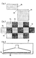
- pixels 84, 86 of the display unit 50 are shown.
- LCD displays have electrically controllable surface areas which can be switched between permeable and non-permeable depending on the control. These are called pixels.
- Pixel 4 are two adjacent pixels 84 of one and the same layer of the display unit 50 are shown.
- the pixels 84 must necessarily be spaced (free space 88) from one another in order to be electrically isolated from one another. This means that pixels of a single layer cannot fill an area in a closed manner.
- the invention therefore proposes an at least two-layer display unit 50, in which the pixels 84 of the one layer are arranged in such a way that they complement the pixels 86 of the other layer to form a surface that is as closed as possible. This is shown in Figure 5.
- the square pixels 84 of the first layer are arranged corresponding to the black fields of a chess board, they are supplemented by the pixels of the second layer (arranged according to the white fields of a chess board) to form a practically closed area.
- very small holes 90 remain. These can be closed by a third layer, which provides pixels in their place.
- the two layers of the display unit are arranged closely adjacent and separated from one another, for example, by a thin glass or plastic pane.
- FIG. 6 An example of a two-layer, linear display unit 50 is given in FIG. It only has a row of pixels 84 in the upper layer and a row 86 of pixels 86 in the lower layer that fills the gap. As is known, each individual pixel can be controlled separately. If all of the pixels 84, 86 of the two rows are driven, the line is either transparent or not permeable.
- the display unit 50 according to FIG. 6 is advantageous in the case of linear scanning of information.
- the row-shaped display unit 50 is scanned with a line-shaped light source, for example a fluorescent tube, the light of which is focused on the line-shaped pixel arrangement. All pixels 84, 86 of both layers can be switched simultaneously.
- a line-shaped light source for example a fluorescent tube
- the multilayer arrangement described can also be used to obtain display units of relatively large area.
- One layer takes over only a partial area of the overall display, the other layer or the other layers take over the remaining areas.
- Each layer has its own control unit, which is relieved due to the area distribution compared to control electronics for the entire area. This results in faster image construction, a higher contrast and a larger format.
Landscapes
- Physics & Mathematics (AREA)
- Nonlinear Science (AREA)
- Mathematical Physics (AREA)
- Chemical & Material Sciences (AREA)
- Crystallography & Structural Chemistry (AREA)
- General Physics & Mathematics (AREA)
- Optics & Photonics (AREA)
- Liquid Crystal (AREA)
- Devices For Indicating Variable Information By Combining Individual Elements (AREA)
- Projection Apparatus (AREA)
Abstract
Description
Die Erfindung bezieht sich auf eine projizierbare, passive Flüssigkeitskristallmatrix-Anzeigevorrichtung mit einer Anzeigeeinheit, der eine elektronische Steuereinheit zugeordnet ist und auf der einzelne flächenhafte Elemente, sogenannte Pixel, die über Leiterbahnen mit der Steuereinheit verbunden sind, zwischen einem lichtdurchlässigen und einem lichtabsorbierenden Zustand schaltbar sind, und mit zwei Polarisationsfiltern, von denen eines im Lichtweg vor, das andere im Lichtweg hinter der Anzeigeeinheit angeordnet ist.The invention relates to a projectable, passive liquid crystal matrix display device with a display unit, to which an electronic control unit is assigned and on which individual planar elements, so-called pixels, which are connected to the control unit via conductor tracks, can be switched between a translucent and a light-absorbing state , and with two polarization filters, one of which is arranged in the light path in front, the other in the light path behind the display unit.
Die Dokumente DE-A-34 13 995 und EP-A-127 701 zeigen bereits Flüssigkeitskristall-Anzeigevorrichtungen dieser Art.The documents DE-A-34 13 995 and EP-A-127 701 already show liquid crystal display devices of this type.
Die bekannten Anzeigevorrichtungen dieser Art sind flache Einheiten, sie werden daher im englischen auch als flat screen bezeichnet. Sie können auf die Projektionsfläche (Gegenstandsebene) eines Overhead-Projektors gelegt werden, wobei sich die Anzeigeeinheit in der Gegenstandsebene befindet. Auf diese Weise kann die in der Anzeigeeinheit befindliche Information in Form von beispielsweise Schrift, Formeln, einer Zeichnung, Flächenelementen oder dergleichen auf die Bildebene (Leinwand, Projektionsfläche) abgebildet werden.The known display devices of this type are flat units and are therefore also referred to as flat screen in English. They can be placed on the projection surface (object level) of an overhead projector, with the display unit in the object level. In this way, the information in the display unit can be mapped onto the image plane (screen, projection surface) in the form of, for example, writing, formulas, a drawing, surface elements or the like.
Bei den vorbekannten Anzeigevorrichtungen sind die Polarisationsfilter mit der eigentlichen Anzeigeeinheit fest verbunden. Dies hat mehrere Nachteile:
- 1. Bei den relativ großflächigen Anzeigeeinheiten müssen auch relativ großflächige Polarisationsfilter verwendet werden. Die üblicherweise verwendeten Polarisationsfilter aus Kunststoffolie haben eine nur begrenzte Lebensdauer, typischerweise eine Lebensdauer von 600 Stunden. Die Polarisationsfolien werden durch Wärme und durch Strahlungsanteile im Beleuchtungslicht, insbesondere durch den UV-Anteil degradiert. Bei der vorbekannten Anzeigevorrichtung muß bei Erschöpfen der Polarisationsfolien die Anzeigeeinheit mit ausgetauscht werden.
- 2. Die Anzeigeeinheit selbst ist wärmeempfindlich. Ein ausreichendes Kontrastverhältnis wird nur unterhalb von 50 Grad, bei moderneren Anzeigeeinheiten sogar nur unterhalb von 40 Grad C erzielt. Durch die für die Projektion benötigte Lichtquelle, die insbesondere einen hohen IR-Energieanteil abstrahlt, heizen sich aber die Polarisationsfolien und die Anzeigeeinheit selbst auf. Der größte Anteil der Absorption findet dabei in der unteren, der Lichtquelle zugewandten Polarisationsfolie statt, die dort anfallende Wärme überträgt sich auch auf die hiermit verbundene Anzeigeeinheit. In der Anzeigeeinheit selbst findet zwar nur eine geringe Absorption statt, sie führt aber ebenfalls zu einer Temperaturerhöhung. Schließlich wird ein weiterer Anteil der Lichtenergie im zweiten Polarisationsfilterfestgehalten und erwärmt dieses. Da auch der zweite Polarisationsfilter mit der Anzeigeeinheit verbunden ist, findet auch hier ein Wärmetransport zur Anzeigeeinheit statt.
- 1. With the relatively large-area display units, relatively large-area polarization filters must also be used. The commonly used polarizing filters made of plastic film have a limited lifespan, typically a lifespan of 600 hours. The polarization films are degraded by heat and by radiation components in the illuminating light, in particular by the UV component. In the known display device, the display unit must also be replaced when the polarization films are exhausted.
- 2. The display unit itself is sensitive to heat. A sufficient contrast ratio is only achieved below 50 degrees, in modern display units even below 40 degrees C. However, due to the light source required for the projection, which in particular emits a high proportion of IR energy, the polarizing foils and the display unit itself heat up. Most of the absorption takes place in the lower polarization film facing the light source, and the heat generated there is also transferred to the display unit connected to it. Although there is only a slight absorption in the display unit itself, it also leads to an increase in temperature. Finally, a further portion of the light energy is held in the second polarization filter and heats it up. Since the second polarization filter is also connected to the display unit, heat is also transported to the display unit here.
Die großflächige Projektion von Flüssigkeitskristallanzeigen war in der Praxis bisher schwierig. Verursacht durch die Wärmezufuhr der Lichtquelle verfärben sich bei Anzeigevorrichtungen nach dem Stand der Technik Bereiche bzw. Pixel der Anzeigeeinheit, die von der Steuereinheit nicht angesprochen sind.The large-scale projection of liquid crystal displays has previously been difficult in practice. Caused by the supply of heat from the light source, areas or pixels of the display unit which are not addressed by the control unit change color in display devices according to the prior art.
Flüssigkeitskristallanzeigen bieten jedoch eine Reihe von Vorteilen, die sie gegenüber anderen Anzeigen auszeichnen, wie geringe Versorgungsspannung, Flimmerfreiheit, geringes Gewicht, flache Gesamthöhe, Transparenz, Freiheit von Strahlenbelastungen. Eine Verwendung für Projektionsgeräte ist daher anzustreben.However, liquid crystal displays offer a number of advantages that distinguish them from other displays, such as low supply voltage, no flicker, low weight, flat overall height, transparency, freedom from radiation exposure. Use for projection devices is therefore desirable.
Hiervon ausgehend liegt der Erfindung die Aufgabe zugrunde, die Flüssigkeitskristall-Anzeigevorrichtungen der eingangs genannten Art, insbesondere Flüssigkeitskristallmatrix-Anzeigen, so weiterzubilden, daß sie sich für die Projektion eignen und insbesondere den Wärmebelastungen Stand halten, die auf dem Projektionstisch eines Overhead-Projektors vorliegen.Proceeding from this, the object of the invention is to further develop the liquid crystal display devices of the type mentioned at the outset, in particular liquid crystal matrix displays, in such a way that they are suitable for projection and in particular withstand the thermal loads which are present on the projection table of an overhead projector.
Diese Aufgabe wird gelöst durch eine Vorrichtung mit den Merkmalen des Patentanspruchs 1.This object is achieved by a device with the features of patent claim 1.
Aufgrund des Abstandes der beiden Polarisationsfilter von der eigentlichen Anzeigeeinheit können die Polarisationsfilter die in ihnen anfallende Wärme nicht unmittelbar an die Anzeigeeinheit weiterleiten. Zudem können die Polarisationsfilter unabhängig von der Anzeigeeinheit ausgetauscht werden. Insbesondere aber wird zwischen der Anzeigeeinheit und dem jeweiligen Polarisationsfilter ein Raum geschaffen, durch den die zur Kühlung dienende Luftströmung fließen kann. Da bei den üblicherweise in horizontalem Zustand betriebenen Anzeigevorrichtungen die Wärme praktisch nicht durch konvektive Luftströmungen abfließt, wird über die erzwungene Luftströmung, die durch einen Ventilator erzeugt wird, eine ständige Kühlung erreicht. Diese Kühlung kommt nicht nur der eigentlichen Anzeigeeinheit zugute, sondern verlängert auch die Lebensdauer der Polarisationsfolien.Because of the distance between the two polarization filters from the actual display unit, the polarization filters cannot directly pass on the heat generated in them to the display unit. In addition, the polarization filters can be replaced independently of the display unit. In particular, however, a space is created between the display unit and the respective polarization filter, through which the air flow serving for cooling can flow. Since in the display devices, which are usually operated in a horizontal state, the heat practically does not flow away through convective air currents, constant cooling is achieved via the forced air flow generated by a fan. This cooling not only benefits the actual display unit, but also extends the life of the polarizing films.
In Weiterbildung der Erfindung befindet sich die Anzeigevorrichtung in einem flachen Gehäuse. Die Anzeigeeinheit selbst hat etwa die Größe der Projektionsfläche von Overhead-Projektoren, beispielsweise DIN A4 oder DIN A5-Format. Das Gehäuse ist nur wenige Zentimeter, z.B. 40 mm, hoch. Dementsprechend beträgt der Abstand zwischen der Anzeigeeinheit und den oberhalb und unterhalb von ihrangeordneten Polarisationsfolien nur mehrere Millimeter, beispielsweise 15 bis 20 mm. Für eine möglichst gleichmäßige Strömung der kühlenden Luft ist es vorteilhaft, wenn die Druckseite des im Gehäuse befindlichen Ventilators überAustrittsöffnungen direkt mit der Außenwelt verbunden ist und die Luft über verschiedene Eintrittsöffnungen durch das Gehäuse hindurch angesaugt wird. Auf diese Weise kann die Luftströmung gezielt über die spezielle Anordnung der Eintrittsöffnungen, über spezielle Luft-leitbleche und dergleichen gesteuert werden. So kann beispielsweise erreicht werden, daß die Mitte der Polarisationsfilter bzw. der Anzeigeeinheit stärker gekühlt wird, dort fällt auch eine höhere Wärme an. Es kann auch erreicht werden, daß die im Luftweg hinten liegenden Bereiche der Filter bzw. Anzeigeeinheit seitlich zugeführte Frischluft bekommen und nicht nur mit Luft gekühlt werden, die bereits durch Kontakt mit anderen Stellen erwärmt ist.In a further development of the invention, the display device is located in a flat housing. The display unit itself has approximately the size of the projection area of overhead projectors, for example DIN A4 or A5 format. The housing is only a few centimeters high, for example 40 mm. Accordingly, the distance between the display unit and the polarization foils arranged above and below it is only a few millimeters, for example 15 to 20 mm. For one if possible moderate flow of the cooling air, it is advantageous if the pressure side of the fan located in the housing is connected directly to the outside world via outlet openings and the air is sucked in through the housing via various inlet openings. In this way, the air flow can be controlled specifically via the special arrangement of the inlet openings, via special air baffles and the like. For example, it can be achieved that the center of the polarization filters or the display unit is cooled more, and there is also a higher heat. It can also be achieved that the areas of the filter or display unit located at the rear in the airway are supplied with fresh air which is fed in laterally and are not only cooled with air which has already been heated by contact with other points.
In vorzugsweiser Weiterbildung der Erfindung wird vorgeschlagen, zumindest eines der Polarisationsfilter mit einer Scheibe aus Glas oder Kunststoff zu verbinden und diese Scheibe schnell lösbar und auswechselbar am Gehäuse zu befestigen. Hierfür bietet sich insbesondere ein Rahmen an, in den die auf ihrer Innenseite mit der Polarisationsfolie beschichtete Scheibe eingelegt werden kann. Die Fixierung kann durch einschnappende Federn, durch schnell lösbare Schrauben, durch abschraubbare Füße oder dergleichen erfolgen. Entscheidend ist dabei, daß die Scheibe von außen auf das Gehäuse aufgelegt wird, das Gehäuse also nicht geöffnet werden muß, um die Scheibe einschließlich der Polarisationsfolie zu entfernen.In a preferred development of the invention, it is proposed to connect at least one of the polarization filters to a pane made of glass or plastic and to fasten this pane in a detachable and replaceable manner to the housing. A frame is particularly suitable for this purpose, into which the pane coated on the inside with the polarizing film can be inserted. The fixation can be done by snapping springs, quick-release screws, unscrewable feet or the like. The decisive factor here is that the pane is placed on the housing from the outside, so that the casing does not have to be opened to remove the pane including the polarizing film.
Sehr vorteilhaft ist es, ein Polarisationsfilter drehbar am Gehäuse anzuordnen. Dabei genügt eine Verdrehbarkeit über einen geringen Winkelbereich, beispielsweise 15 Grad. Durch die Drehung kann die Färbe, in der die Projektion erscheint, verändert werden.It is very advantageous to arrange a polarization filter rotatably on the housing. A rotatability over a small angular range, for example 15 degrees, is sufficient. Rotation can change the color in which the projection appears.
Sehr vorteilhaft ist auch, die Trägerplatten für die Polarisationsfolien und die eigentliche Anzeigeeinheit mit einem UV-Schutzfilter, insbesondere einer aufgedampften oder geklebten Schicht, zu versehen. Hierdurch wird vermieden, daß der einergiereiche UV-Anteil zu chemischen Prozessen und anderen schädigenden Einflüssen führt. Auch eine Antireflexschicht bzw. -folie an den Oberflächen der Polarisationsfilter, Platten, der Anzeigeeinheit usw. ist vorteilhaft, hierdurch wird die Lichtreflexion innerhalb dervielschichtigen Einheit und damit der Lichtverlust verringert.It is also very advantageous to provide the carrier plates for the polarizing films and the actual display unit with a UV protection filter, in particular a vapor-deposited or glued layer. This avoids that the greedy UV component leads to chemical processes and other damaging influences. An anti-reflective layer or film on the surfaces of the polarization filters, plates, the display unit etc. is also advantageous, as a result of which the light reflection within the multilayer unit and thus the loss of light are reduced.
Als sehr günstig hat sich schließlich herausgestellt, die Anzeigeeinheit so zu betreiben, daß je nach Darstellung möglichst viele Pixel angeregt sind. Will man beispielsweise Schrift darstellen, so werden nicht die die einzelnen Buchstaben bildenden Pixel angeregt, vielmehr wird (in Negativdarstellung) die gesamte Restfläche angeregt. Es hat sich herausgestellt, daß angeregte Pixel unempfindlicher gegen Wärme und sonstige Einflüsse bei der Projektion sind. Eine Ansteuerung der Anzeigeeinheit dahingehend, daß je nach Darstellung die größtmögliche Anzahl von Pixeln angeregt ist, verbessert den Kontrast. Die gewünschte Darstellung auf der Projektionsfläche (Negativ- oder Positivdarstellung) kann über die Steuereinheit erreicht werden. Wird also beispielsweise die Anzeigeeinheit bei inverser Darstellung betrieben und wünscht man eine Positivdarstellung, so wird die Steuereinheit so ausgelegt oder angesteuert, daß sie invers arbeitet.It has finally proven to be very cheap to operate the display unit in such a way that as many pixels as possible are excited, depending on the display. For example, if you want to display writing, the pixels forming the individual letters are not excited, rather the entire remaining area is excited (in a negative representation). It has been found that excited pixels are less sensitive to heat and other influences during projection. Controlling the display unit in such a way that the largest possible number of pixels is excited, depending on the display, improves the contrast. The desired display on the projection surface (negative or positive display) can be achieved via the control unit. If, for example, the display unit is operated with an inverse display and a positive display is desired, the control unit is designed or controlled in such a way that it works inversely.
Schließlich bezieht sich die Erfindung noch auf eine Verbesserung der Anzeigeeinheit selbst. Bei einer einschichtigen Anzeigeeinheit befinden sich alle Pixel in derselben Ebene. Die einzelnen Pixel müssen aber notwendigerweise voneinander elektrisch isoliert sein. Hierdurch ergeben sich zwangsläufig Leerflächen zwischen den einzelnen Pixeln. Bei einschichtigen Anzeigeeinheiten ist es nicht möglich, eine Fläche vollständig abzudunkeln bzw. vollständig aufzuhellen. Um hier nun Abhilfe zu schaffen, wird vorgeschlagen, die Anzeigeeinheit mindestens zweischichtig auszubilden und die Pixel in der zweiten Schicht so anzuordnen, daß sie die Leerräume zwischen den Pixeln der ersten Schicht ausfüllen und umgekehrt. Auf diese Weise kann bei einer schon zweischichtigen Anzeigeeinheit erreicht werden, daß eine Fläche praktisch vollständig abgedunkelt werden bzw. aufgehellt werden kann, wobei lediglich prozentual sehr kleine, punktförmige Restflächen bleiben, die nicht dengleichen Zustand haben wie die Pixel. Diese können noch dadurch abgedunkelt bzw. aufgehelltwerden, daß ihnen mit einer dritten Schicht bzw. Ebene der Anzeigeeinheit Pixel zugeordnet sind. Die Anzeigeeinheit ist damit so ausgelegt, daß bei senkrechter Betrachtung auf die Anzeigefläche die Pixel der verschiedenen Schichten sich zu einer möglichst geschlossenen Fläche ergänzen. Durch das beschriebene versetzte Zusammenfügen zweier und mehrerer Schichten (Informationsebenen) zu einer Gesamtfläche lassen sich die bei Flüssigkeitskristallanzeigen beliebiger Betriebsart grundsätzlich auftretenden Abstände zwischen den Pixeln eines Zeichens bzw. einer Darstellung vermeiden.Finally, the invention relates to an improvement of the display unit itself. In a single-layer display unit, all pixels are in the same plane. However, the individual pixels must necessarily be electrically isolated from one another. This inevitably results in empty spaces between the individual pixels. With single-layer display units, it is not possible to completely darken or completely lighten an area. In order to remedy this situation, it is proposed to design the display unit at least in two layers and to arrange the pixels in the second layer such that they fill the empty spaces between the pixels of the first layer and vice versa. In this way, it can be achieved with a display unit that is already two-layered that an area can be virtually completely darkened or lightened, leaving only small, punctiform residual areas in percent that do not have the same state as the pixels. These can be darkened or brightened by assigning pixels to them with a third layer or level of the display unit. The display unit is thus designed such that when viewed vertically on the display surface, the pixels of the various layers complement one another to form a closed surface. The described staggered combination of two and more layers (information levels) to form a total area makes it possible to avoid the distances between the pixels of a character or a representation that generally occur in liquid crystal displays in any operating mode.
Verwendet man anstelle der Polarisationsfilter oder zusätzlich zu diesen Farbfilter, so werden diese ebenfalls im Abstand von der Anzeigeeinheit angeordnet und befinden sich im Kühlluftstrom.If one uses instead of the polarization filters or in addition to these color filters, these are also arranged at a distance from the display unit and are located in the cooling air flow.
Ein bevorzugtes, jedoch nicht einschränkend zu verstehendes Ausführungsbeispiel der Erfindung wird im folgenden unter Bezugnahme auf die Zeichnung näher erläutert. In dieser zeigen:
- Fig. 1 ein Schnittbild durch eine Anzeigevorrichtung für Overhead-Projektoren in Seitenansicht,
- Fig. 2 eine teilweise schnittbildlich ausgeführte Draufsicht auf die Anzeigevorrichtung gemäß Fig.1,
- Fig. 3 ein Detailschnittbild durch den Bereich eines Stützfußes,
- Fig. 4 eine Darstellung zweier benachbarter Pixel, die sich in einer Schicht der Anzeigeeinheit befinden,
- Fig. 5 eine Darstellung von jeweils sieben Pixeln, die sich in zwei unterschiedlichen Schichten einer doppelschichtigen Anzeigeeinheit befinden, und
- Fig. 6 eine Darstellung einer linienhaften Anzeigeeinheit mit zwei Schichten.
- 1 is a sectional view through a display device for overhead projectors in side view,
- 2 shows a partially sectional top view of the display device according to FIG. 1,
- 3 shows a detailed sectional view through the area of a support foot,
- 4 shows two neighboring pixels that are located in one layer of the display unit,
- 5 shows a representation of seven pixels each, which are located in two different layers of a double-layer display unit, and
- 6 shows an illustration of a linear display unit with two layers.
Die Anzeigevorrichtung nach Figur 1 befindet sich auf einer oberen, horizontalen Platte 20 mit Glaseinsatz 22 eines hier nicht weiter dargestellten Overhead-Projektors. Die Anzeigeeinheit hat ein flaches, im wesentlichen kubisches Gehäuse, von dem in der Figur die rechte Seitenwand 24, die linke Seitenwand 26, die obere Wand 28 und die untere Wand 30 gezeigt sind. In die obere und untere Wand 28, 30 sind jeweils quadratische Glasplatten 32, 34 oberflächenbündig eingesetzt. Sie tragen an ihren Innenseiten ein etwa gleichformatiges, mit ihnen flächig verklebtes Polarisationsfilter 36 bzw. 38. Beide Glasplatten 32, 34 einschließlich des von ihnen getragenen Polarisationsfilters 36 bzw. 38 können rasch und ohne das Gehäuse zu öffnen von außen montiert und demontiert werden. In der Figur 1 ist dies für die untere Glasplatte 34 gezeigt, ergänzend wird auf Figur 3 Bezug genommen. Die Glasplatte 34 wird zum Gehäuseinneren hin durch einen rahmenförmigen umlaufenden, L-förmigen Flansch 40 abgestützt. Ein ebenfalls L-förmiges, elastisches, rahmenförmiges Teil 42 sichert eine nachgiebige Lagerung. Gegen den Flansch 40 wird die Glasplatte 34 durch mit zylindrischen Füßen 44 verbundene Scheiben 46 gepreßt, es sind insgesamt vier Füße 44 vorgesehen. In ihnen befindet sich ein Innengewinde. Mit dem Gehäuse ist eine Schraube 48 fest verbunden, beispielsweise verklebt, die mit ihrem Gewindestift nach außen ragt und in das Innengewinde des zugehörigen Fußes 44 eingreift. Werden die vier Füße 44 abgeschraubt, so kann die Glasplatte 34 einschließlich des zugehörigen Polarisationsfilters 38 entnommen werden.The display device according to FIG. 1 is located on an upper,
Zwischen den beiden Glasplatten 32, 34 befindet sich etwa mittig eine im wesentlichen gleich großeAnzeigeeinheit 50 in LCD-Technik, ihr ist eine Steuereinheit 52 zugeordnet. Pfeile 54 deuten den Lichtfluß des Overhead-Projektors an. Durch dieses Licht, das neben dem sichtbaren Anteil auch einen UV-Anteil und einen IR-Anteil aufweist und insbesondere in den Teilen 36, 38 und 50 teilweise absorbiert wird, heizen sich die genannten Teil auf. Sie werden gekühlt durch folgende beschriebene Kühlungsströme.Between the two
In derrechten Seitenwand 24 ist eine Vielzahl von Löchern 56 vorgesehen, durch die Luft in das Gehäuseinnere (Pfeile 58) strömt. Diese Luft fließt durch die kanalartigen Zwischenräume oberhalb und unterhalb der Anzeigeeinheit 50. Sie streicht bevorzugt über das untere Polarisationsfilter 38, in dem die größte Lichtabsorption und damit die größte Wärmeentwicklung stattfindet. Die Löcher 56 sind weiterhin so angeordnet, daß bevorzugt der mittige Bereich der Polarisationsfilter 36, 38 gekühlt wird.A plurality of
Zusätzlich wird durch seitliche Öffnungen 60 Seitenluft (Pfeile 62) angesaugt. Den Öffnungen 60 sind Luftleitbleche 64 zugeordnet. Die seitliche Luft im Sinne der Pfeile 62 bewirkt, daß auch die in Strömungsrichtung hintenliegenden Bereiche der Teile 36, 38 und 50 ausreichend und nicht nur durch die an dieser Stelle schon etwas erwärmte Luft im Sinne der Pfeile 58 gekühlt werden.In addition, 60 side air (arrows 62) is drawn in through side openings. Air baffles 64 are assigned to the
In Nähe der linken Seitenwand 26 befindet sich eine Vielzahl von Austrittslöchern 66. Unmittelbar vor ihnen ist ein Ventilator 68 eines sonst nicht weiter dargestellten Gebläses angeordnet, der die beschriebenen Luftbewegungen antreibt. In einer (nicht dargestellten) Alternative können die Austrittslöcher auch in der unteren Wand 30 unterhalb des dargetellten Ventilators 68 angeordnet sein, dieser hat dann eine um neunzig Grad gedrehte Achse.In the vicinity of the
Schließlich sind parallel zu großen Stirnwänden 70, 72 und etwa in Verlängerung von diesen nach unten zwei Leitbleche 75 vorgesehen, die nur wesentlich kürzer als die Füße 44 sind. In der unteren Wand 30 befinden sich Lufteintrittslöcher 76, denen Luftleitbleche zugeordnet sind. Die Anordnung ist so getroffen, daß Luft im Sinne der Pfeile 78 an der Unterseite der unteren Glasplatte 34 vorbeistreicht und diese kühlt. Auf diese Weise wird die besonders große Wärmeentwicklung im unteren Polarisationsfilter 38 (etwa 65% der Gesamtlichtabsorption findet dort statt) abgeleitet.Finally, two
Aus Figur 2 sind die einzelnen Luftströme in Draufsicht erkennbar. Die Figur zeigt, daß insbesondere die mittigen Bereiche der Teile 36, 38 bzw. 50 gekühlt werden. Die gezielte Kühlung wird einerseits durch die Bemessung der Eintrittslöcher 56, 60, 76 und andererseits durch Luftleitbleche, wie sie mit den Bezugsziffern 64 und 74 angedeutet sind, erreicht. Die am weitesten vom Ventilator68 entfernten Löcher 56 haben den größten Durchmesser, je näher die Lufteintrittsöffnungen am Ventilator sind, desto kleiner wird im allgemeinen ihr Durchmesser.The individual air streams can be seen in plan view from FIG. The figure shows that in particular the central areas of the
Die zueinander parallelen Oberflächen der Teile 32 bis 38 und 50 sind mit einer Antireflexschicht 80 versehen. Weiterhin sind UV-Schutzfilter 82 vorzugsweise im Lichtweg (Pfeile 54) vor der Anzeigeeinheit 50 vorgesehen, sie sind durch das Bezugszeichen 82 angedeutet. Nicht dargestellt ist die Möglichkeit, ein Polarisationsfilter, zum Beispiel das obere Polarisationsfilter 36, um eine parallel zu den Pfeilen 54 verlaufende Achse zu drehen. Hierfür können bekannte Mechanismen eingesetzt werden.The mutually parallel surfaces of the
In den Figuren 4 und 5 sind Pixel 84, 86 der Anzeigeeinheit 50 gezeigt. In bekannter Weise haben LCD-Anzeigen elektrisch ansteuerbare Flächenbereiche, die je nach Ansteuerung zwischen durchlässig und nicht-durchlässig geschaltet werden können. Diese werden als Pixel bezeichnet. In Figur 4 sind zwei benachbarte Pixel 84 ein und derselben Schicht der Anzeigeeinheit 50 gezeigt. Die Pixel 84 müssen notwendigerweise einen Abstand (Freiraum 88) voneinander haben, um elektrisch voneinander isoliert zu sein. Dies bedeutet, daß Pixel einer einzigen Schicht eine Fläche nicht geschlossen ausfüllen können. Die Erfindung schlägt daher eine zumindest zweischichtige Anzeigeeinheit 50 vor, bei der die Pixel 84 der einen Schicht so angeordnet sind, daß sie die Pixel 86 der anderen Schicht zu einer möglichst geschlossenen Fläche ergänzen. Dies ist in Figur 5 dargestellt. Die quadratischen Pixel 84 der ersten Schicht sind entsprechend den schwarzen Feldern eines Schachbrettes angeordnet, sie werden durch die (entsprechend den weißen Feldern eines Schachbrettes angeordneten) Pixel der zweiten Schicht zu einer praktisch geschlossenen Fläche ergänzt. Es verbleiben aber sehr kleine Löcher 90. Diese können durch eine dritte Schicht, die an ihrer Stelle Pixel vorsieht, geschlossen werden.4 and 5,
Die beiden Schichten der Anzeigeeinheit sind eng benachbart angeordnet und beispielsweise durch eine dünnen Glas- oder Kunststoffscheibe voneinander getrennt.The two layers of the display unit are arranged closely adjacent and separated from one another, for example, by a thin glass or plastic pane.
In Figur 6 ist ein Beispiel einer zweischichtigen, linearen Anzeigeeinheit 50 gegeben. Sie weist lediglich eine Reihe Pixel 84 in der oberen Schicht und eine exakt darunter liegende, lückenfüllende Reihe Pixel 86 in der unteren Schicht auf. Bekanntlich kann jeder einzelne Pixel separat angesteuert werden. Werden alle Pixel 84, 86 der beiden Reihen angesteuert, so ist die Linie entweder transparent oder nicht durchlässig. Die Anzeigeeinheit 50 gemäß Figur 6 ist vorteilhaft bei einer linienhaften Abtastung einer Information. Die reihenförmige Anzeigeeinheit 50 wird mit einer strichförmigen Lichtquelle, beispielsweise einer Leuchtstoffröhre, abgetastet, deren Licht auf die strichförmige Pixelanordnung fokussiert wird. Alle Pixel 84, 86 beider Schichten können gleichzeitig geschaltet werden.An example of a two-layer,
Die beschriebene Mehrschichtanordnung kann aber auch dazu benutzt werden, um relativ großflächige Anzeigeeinheiten zu erhalten. Eine Schicht übernimmt dabei nur einen Teilbereich der Gesamtanzeige, die andere Schicht oder die anderen Schichten übernehmen die restlichen Flächenanteile. Jede Schicht besitzt eine eigene Steuereinheit, die auf Grund der flächenmäßigen Aufteilung entlastet ist gegenüber einer Ansteuerungselektronik für die gesamte Fläche. Hierdurch ergibt sich ein schnellerer Bildaufbau, ein höherer Kontrast und ein größeres Format.However, the multilayer arrangement described can also be used to obtain display units of relatively large area. One layer takes over only a partial area of the overall display, the other layer or the other layers take over the remaining areas. Each layer has its own control unit, which is relieved due to the area distribution compared to control electronics for the entire area. This results in faster image construction, a higher contrast and a larger format.
Claims (8)
Priority Applications (1)
| Application Number | Priority Date | Filing Date | Title |
|---|---|---|---|
| AT87903255T ATE54761T1 (en) | 1986-05-27 | 1987-05-27 | PROJECTABLE PASSIVE LIQUID CRYSTAL DISPLAY DEVICE. |
Applications Claiming Priority (2)
| Application Number | Priority Date | Filing Date | Title |
|---|---|---|---|
| DE3617784 | 1986-05-27 | ||
| DE19863617784 DE3617784A1 (en) | 1986-05-27 | 1986-05-27 | PROJECTABLE PASSIVE LIQUID CRYSTAL MATRIX DISPLAY IN MULTILAYER ARCHITECTURE WITH INTERCHANGEABLE FRAME AND REMOVABLE FILTERS |
Publications (3)
| Publication Number | Publication Date |
|---|---|
| EP0268620A1 EP0268620A1 (en) | 1988-06-01 |
| EP0268620B1 EP0268620B1 (en) | 1990-07-18 |
| EP0268620B2 true EP0268620B2 (en) | 1993-10-06 |
Family
ID=6301716
Family Applications (1)
| Application Number | Title | Priority Date | Filing Date |
|---|---|---|---|
| EP19870903255 Expired - Lifetime EP0268620B2 (en) | 1986-05-27 | 1987-05-27 | Projectable passive liquid crystal display |
Country Status (3)
| Country | Link |
|---|---|
| EP (1) | EP0268620B2 (en) |
| JP (1) | JP2556982B2 (en) |
| DE (1) | DE3617784A1 (en) |
Families Citing this family (4)
| Publication number | Priority date | Publication date | Assignee | Title |
|---|---|---|---|---|
| JPS6338180U (en) * | 1986-08-26 | 1988-03-11 | ||
| JPH07104517B2 (en) * | 1989-02-09 | 1995-11-13 | シャープ株式会社 | Projection type liquid crystal display device |
| DE102005003181B4 (en) * | 2005-01-19 | 2013-09-19 | Volkswagen Ag | Multifunction window pane and method for operating the multifunctional window pane |
| DE202007000047U1 (en) | 2007-11-22 | 2008-04-30 | Hannemann, Achim | display unit |
Family Cites Families (9)
| Publication number | Priority date | Publication date | Assignee | Title |
|---|---|---|---|---|
| US4171874A (en) * | 1975-02-03 | 1979-10-23 | General Electric Company | Evenly illuminated display devices |
| CH604258B5 (en) * | 1976-04-02 | 1978-08-31 | Ebauches Sa | |
| DE3105601A1 (en) * | 1981-02-16 | 1982-09-02 | Siemens AG, 1000 Berlin und 8000 München | DATA VISION DEVICE |
| JPS58211742A (en) * | 1982-06-04 | 1983-12-09 | Alps Electric Co Ltd | Information display device for moving body |
| GB2150726B (en) * | 1983-11-30 | 1988-01-20 | Standard Telephones Cables Ltd | Office terminals |
| JPS60186889A (en) * | 1984-03-07 | 1985-09-24 | スタンレー電気株式会社 | Multi-layer matrix type liquid crystal display unit |
| JPS6117134A (en) * | 1984-04-13 | 1986-01-25 | デモルツクス・ゲ−・エム・ベ−・ハ−・ウント・コンパニ−・カ−・ゲ− | Overhead type projector |
| JPS62109024A (en) * | 1985-11-07 | 1987-05-20 | Kawasaki Heavy Ind Ltd | Structure for combining liquid crystal panel for image projection |
| JPS62110975U (en) * | 1985-12-28 | 1987-07-15 |
-
1986
- 1986-05-27 DE DE19863617784 patent/DE3617784A1/en active Granted
-
1987
- 1987-05-27 EP EP19870903255 patent/EP0268620B2/en not_active Expired - Lifetime
- 1987-05-27 JP JP62503275A patent/JP2556982B2/en not_active Expired - Lifetime
Also Published As
| Publication number | Publication date |
|---|---|
| JPS63503408A (en) | 1988-12-08 |
| EP0268620A1 (en) | 1988-06-01 |
| JP2556982B2 (en) | 1996-11-27 |
| EP0268620B1 (en) | 1990-07-18 |
| DE3617784A1 (en) | 1987-12-03 |
| DE3617784C2 (en) | 1993-02-04 |
Similar Documents
| Publication | Publication Date | Title |
|---|---|---|
| DE69207633T2 (en) | Illuminated display device | |
| US4952925A (en) | Projectable passive liquid-crystal flat screen information centers | |
| WO1987007394A1 (en) | Projectable passive liquid crystal display | |
| DE112006003466T5 (en) | Liquid crystal display unit | |
| DE3501006A1 (en) | LIQUID CRYSTAL COLOR INDICATOR | |
| DE60010548T2 (en) | Projector with electro-optical modulator and prism | |
| DE102016122694A1 (en) | Background lighting unit and the same having liquid crystal display device | |
| CH666560A5 (en) | DISPLAY DEVICE. | |
| DE3106415C2 (en) | "Display and recording system with a liquid crystal cell" | |
| DE2160611A1 (en) | Liquid crystal display device with improved optical contrast | |
| DE3235057A1 (en) | SIGN PROJECTION UNIT | |
| EP0268620B2 (en) | Projectable passive liquid crystal display | |
| EP2063312B1 (en) | Display unit | |
| DE3506968C2 (en) | ||
| DE20019350U1 (en) | Device for shadow-free backlighting of large-area displays | |
| DE10064075A1 (en) | Sub-assembly structure for a DC microwave oven | |
| DE4223303A1 (en) | Plasma-addressed liquid crystal display with parallel barriers - has barriers formed on lower substrate with strips of second electrode in spaces insulated from overall first electrode | |
| DE102005030668B4 (en) | Direct backlight unit | |
| DE2449929A1 (en) | PROJECTION APPARATUS | |
| DE102004025266A1 (en) | Lighting system with a housing and a flat lamp arranged therein | |
| DE3302156A1 (en) | LIGHTING DEVICE FOR A TRANSMISSIVELY OPERABLE PASSIVE DISPLAY | |
| DE8815708U1 (en) | Device for projecting electronically generated images | |
| DE102005025433A1 (en) | Lichtaufteilvorrichtung | |
| DE3626146A1 (en) | Transparent liquid-crystal display | |
| DE3014016A1 (en) | Low power darkroom safe-light - has array of LEDS with selective spectral range, and reflector strip to improve lamp output |
Legal Events
| Date | Code | Title | Description |
|---|---|---|---|
| PUAI | Public reference made under article 153(3) epc to a published international application that has entered the european phase |
Free format text: ORIGINAL CODE: 0009012 |
|
| AK | Designated contracting states |
Kind code of ref document: A1 Designated state(s): AT BE CH DE FR GB IT LI NL SE |
|
| 17P | Request for examination filed |
Effective date: 19880603 |
|
| 17Q | First examination report despatched |
Effective date: 19891213 |
|
| GRAA | (expected) grant |
Free format text: ORIGINAL CODE: 0009210 |
|
| AK | Designated contracting states |
Kind code of ref document: B1 Designated state(s): AT BE CH DE FR GB IT LI NL SE |
|
| PG25 | Lapsed in a contracting state [announced via postgrant information from national office to epo] |
Ref country code: BE Effective date: 19900718 Ref country code: NL Effective date: 19900718 Ref country code: SE Effective date: 19900718 Ref country code: IT Free format text: LAPSE BECAUSE OF FAILURE TO SUBMIT A TRANSLATION OF THE DESCRIPTION OR TO PAY THE FEE WITHIN THE PRE;WARNING: LAPSES OF ITALIAN PATENTS WITH EFFECTIVE DATE BEFORE 2007 MAY HAVE OCCURRED AT ANY TIME BEFORE 2007. THE CORRECT EFFECTIVE DATE MAY BE DIFFERENT FROM THE ONE RECORDED.SCRIBED TIME-LIMIT Effective date: 19900718 |
|
| REF | Corresponds to: |
Ref document number: 54761 Country of ref document: AT Date of ref document: 19900815 Kind code of ref document: T |
|
| REF | Corresponds to: |
Ref document number: 3763804 Country of ref document: DE Date of ref document: 19900823 |
|
| PLBI | Opposition filed |
Free format text: ORIGINAL CODE: 0009260 |
|
| ET | Fr: translation filed | ||
| 26 | Opposition filed |
Opponent name: ED. LIESEGANG Effective date: 19901030 |
|
| GBT | Gb: translation of ep patent filed (gb section 77(6)(a)/1977) | ||
| NLV1 | Nl: lapsed or annulled due to failure to fulfill the requirements of art. 29p and 29m of the patents act | ||
| PGFP | Annual fee paid to national office [announced via postgrant information from national office to epo] |
Ref country code: AT Payment date: 19930526 Year of fee payment: 7 |
|
| PUAH | Patent maintained in amended form |
Free format text: ORIGINAL CODE: 0009272 |
|
| STAA | Information on the status of an ep patent application or granted ep patent |
Free format text: STATUS: PATENT MAINTAINED AS AMENDED |
|
| 27A | Patent maintained in amended form |
Effective date: 19931006 |
|
| AK | Designated contracting states |
Kind code of ref document: B2 Designated state(s): AT BE CH DE FR GB IT LI NL SE |
|
| ET3 | Fr: translation filed ** decision concerning opposition | ||
| GBTA | Gb: translation of amended ep patent filed (gb section 77(6)(b)/1977) | ||
| PG25 | Lapsed in a contracting state [announced via postgrant information from national office to epo] |
Ref country code: AT Effective date: 19940527 |
|
| PGFP | Annual fee paid to national office [announced via postgrant information from national office to epo] |
Ref country code: GB Payment date: 19950615 Year of fee payment: 9 |
|
| PGFP | Annual fee paid to national office [announced via postgrant information from national office to epo] |
Ref country code: CH Payment date: 19950620 Year of fee payment: 9 |
|
| PG25 | Lapsed in a contracting state [announced via postgrant information from national office to epo] |
Ref country code: GB Effective date: 19960527 |
|
| PG25 | Lapsed in a contracting state [announced via postgrant information from national office to epo] |
Ref country code: LI Effective date: 19960531 Ref country code: CH Effective date: 19960531 |
|
| APAC | Appeal dossier modified |
Free format text: ORIGINAL CODE: EPIDOS NOAPO |
|
| APAC | Appeal dossier modified |
Free format text: ORIGINAL CODE: EPIDOS NOAPO |
|
| REG | Reference to a national code |
Ref country code: CH Ref legal event code: PL |
|
| GBPC | Gb: european patent ceased through non-payment of renewal fee |
Effective date: 19960527 |
|
| REG | Reference to a national code |
Ref country code: CH Ref legal event code: AEN Free format text: AUFRECHTERHALTUNG DES PATENTES IN GEAENDERTER FORM |
|
| PGFP | Annual fee paid to national office [announced via postgrant information from national office to epo] |
Ref country code: DE Payment date: 19981028 Year of fee payment: 20 |
|
| REG | Reference to a national code |
Ref country code: FR Ref legal event code: TP |
|
| REG | Reference to a national code |
Ref country code: FR Ref legal event code: TP |
|
| APAH | Appeal reference modified |
Free format text: ORIGINAL CODE: EPIDOSCREFNO |
|
| PGFP | Annual fee paid to national office [announced via postgrant information from national office to epo] |
Ref country code: FR Payment date: 20060515 Year of fee payment: 20 |
|
| PLAB | Opposition data, opponent's data or that of the opponent's representative modified |
Free format text: ORIGINAL CODE: 0009299OPPO |