EP0268362B1 - Heated dish antennas - Google Patents
Heated dish antennas Download PDFInfo
- Publication number
- EP0268362B1 EP0268362B1 EP87308610A EP87308610A EP0268362B1 EP 0268362 B1 EP0268362 B1 EP 0268362B1 EP 87308610 A EP87308610 A EP 87308610A EP 87308610 A EP87308610 A EP 87308610A EP 0268362 B1 EP0268362 B1 EP 0268362B1
- Authority
- EP
- European Patent Office
- Prior art keywords
- heater
- antenna
- assembly according
- dish antenna
- secured
- Prior art date
- Legal status (The legal status is an assumption and is not a legal conclusion. Google has not performed a legal analysis and makes no representation as to the accuracy of the status listed.)
- Expired - Lifetime
Links
- 229920001940 conductive polymer Polymers 0.000 claims abstract description 9
- 238000010438 heat treatment Methods 0.000 claims description 17
- 229910052751 metal Inorganic materials 0.000 claims description 12
- 239000002184 metal Substances 0.000 claims description 12
- 230000005855 radiation Effects 0.000 claims description 8
- 239000011888 foil Substances 0.000 claims description 7
- 239000000463 material Substances 0.000 claims description 7
- 239000012774 insulation material Substances 0.000 claims description 2
- 230000001747 exhibiting effect Effects 0.000 claims 1
- RYGMFSIKBFXOCR-UHFFFAOYSA-N Copper Chemical compound [Cu] RYGMFSIKBFXOCR-UHFFFAOYSA-N 0.000 description 4
- 239000000203 mixture Substances 0.000 description 4
- 229910052802 copper Inorganic materials 0.000 description 3
- 239000010949 copper Substances 0.000 description 3
- 238000009413 insulation Methods 0.000 description 3
- 238000000034 method Methods 0.000 description 3
- 239000003973 paint Substances 0.000 description 3
- PXHVJJICTQNCMI-UHFFFAOYSA-N Nickel Chemical compound [Ni] PXHVJJICTQNCMI-UHFFFAOYSA-N 0.000 description 2
- 229910052782 aluminium Inorganic materials 0.000 description 2
- XAGFODPZIPBFFR-UHFFFAOYSA-N aluminium Chemical compound [Al] XAGFODPZIPBFFR-UHFFFAOYSA-N 0.000 description 2
- 239000004020 conductor Substances 0.000 description 2
- 230000000694 effects Effects 0.000 description 2
- 239000011152 fibreglass Substances 0.000 description 2
- 229920001903 high density polyethylene Polymers 0.000 description 2
- 239000004700 high-density polyethylene Substances 0.000 description 2
- 239000000843 powder Substances 0.000 description 2
- 230000035945 sensitivity Effects 0.000 description 2
- 239000000126 substance Substances 0.000 description 2
- 229920002799 BoPET Polymers 0.000 description 1
- OKTJSMMVPCPJKN-UHFFFAOYSA-N Carbon Chemical compound [C] OKTJSMMVPCPJKN-UHFFFAOYSA-N 0.000 description 1
- 244000187656 Eucalyptus cornuta Species 0.000 description 1
- 229920000339 Marlex Polymers 0.000 description 1
- 229920005830 Polyurethane Foam Polymers 0.000 description 1
- HCHKCACWOHOZIP-UHFFFAOYSA-N Zinc Chemical compound [Zn] HCHKCACWOHOZIP-UHFFFAOYSA-N 0.000 description 1
- WYTGDNHDOZPMIW-RCBQFDQVSA-N alstonine Natural products C1=CC2=C3C=CC=CC3=NC2=C2N1C[C@H]1[C@H](C)OC=C(C(=O)OC)[C@H]1C2 WYTGDNHDOZPMIW-RCBQFDQVSA-N 0.000 description 1
- 239000003963 antioxidant agent Substances 0.000 description 1
- 230000003078 antioxidant effect Effects 0.000 description 1
- 230000005540 biological transmission Effects 0.000 description 1
- 239000006229 carbon black Substances 0.000 description 1
- 239000011248 coating agent Substances 0.000 description 1
- 238000000576 coating method Methods 0.000 description 1
- 150000001875 compounds Chemical class 0.000 description 1
- 238000001816 cooling Methods 0.000 description 1
- 239000011889 copper foil Substances 0.000 description 1
- 230000003247 decreasing effect Effects 0.000 description 1
- 230000002500 effect on skin Effects 0.000 description 1
- 238000010894 electron beam technology Methods 0.000 description 1
- 230000001788 irregular Effects 0.000 description 1
- 229910001120 nichrome Inorganic materials 0.000 description 1
- 229910052759 nickel Inorganic materials 0.000 description 1
- 238000013021 overheating Methods 0.000 description 1
- 238000010422 painting Methods 0.000 description 1
- 239000002245 particle Substances 0.000 description 1
- 239000003208 petroleum Substances 0.000 description 1
- 239000004033 plastic Substances 0.000 description 1
- 229920003023 plastic Polymers 0.000 description 1
- 229920000642 polymer Polymers 0.000 description 1
- 239000011496 polyurethane foam Substances 0.000 description 1
- 238000000926 separation method Methods 0.000 description 1
- 238000005476 soldering Methods 0.000 description 1
- 239000011800 void material Substances 0.000 description 1
- 229910052725 zinc Inorganic materials 0.000 description 1
- 239000011701 zinc Substances 0.000 description 1
Images

Classifications
-
- H—ELECTRICITY
- H01—ELECTRIC ELEMENTS
- H01Q—ANTENNAS, i.e. RADIO AERIALS
- H01Q1/00—Details of, or arrangements associated with, antennas
- H01Q1/27—Adaptation for use in or on movable bodies
- H01Q1/28—Adaptation for use in or on aircraft, missiles, satellites, or balloons
-
- H—ELECTRICITY
- H01—ELECTRIC ELEMENTS
- H01Q—ANTENNAS, i.e. RADIO AERIALS
- H01Q1/00—Details of, or arrangements associated with, antennas
- H01Q1/02—Arrangements for de-icing; Arrangements for drying-out ; Arrangements for cooling; Arrangements for preventing corrosion
Definitions
- This invention relates to dish antennas, eg. for receiving and/or transmitting signals from satellites or terrestrial microwave antennas, and in particular means for heating such antennas.
- dish antennas particularly for receiving signals from satellites
- Dish antennas vary widely in size, but many have diameters of 1 to 7 meters; for example, 1.2 meter and 1.8 meter aperture antennas are most frequently used for signals in the 12-14 GHz band which is widely used for private networks transmitting data, voice and video communications.
- regulations eg. United States FCC Regulation 25.209, which set requirements, eg. radiation pattern sidelobe envelope requirements, for both transmit and receive antennas, and a major concern of antenna manufacturers and users is to ensure not only that antennas meet those requirements when first manufactured, but also that they do not become distorted subsequently, so that the requirements are no longer met.
- dish antennas can be very satisfactorily heated, and thus kept free of ice and snow, by means of an electrical heater which is placed behind the antenna and spaced apart therefrom, so that the antenna is heated by radiation from the heater.
- the present invention provides a dish antenna assembly which comprises
- the heaters used in this invention preferably comprise a resistive element in the form of a sheet; however they can alternatively comprise one or more strip heaters secured to a thermally conductive sheet, preferably of metal. All such heaters are included in the term "sheet heater” or “heater in the form of a sheet” as used herein.
- the sheet heater must be positioned so that it is substantially separated from the antenna by a medium which is substantially transparent to thermal radiation, usually air, so that heat generated by the heater radiates from the heater through the medium and strikes the back surface of the antenna.
- a medium which is substantially transparent to thermal radiation usually air
- heat generated by the heater radiates from the heater through the medium and strikes the back surface of the antenna.
- the distance between the first surface of the heater and the back surface of the antenna is 3 to 6 inches (7.6 to 15.2 cm).
- heating of the antenna takes place mainly or exclusively by conduction.
- little or none of the heating of the antenna is the result of conduction and a substantial proportion, preferably at least 40%, particularly at least 60%, of the heating of the antenna is the result of radiation.
- the antenna is generally also heated by free convection from air (or other gas) which lies between the antenna and the heater.
- the air is preferably still air, i.e. any movement thereof is solely the result of convection currents.
- the heat transferred by radiation from the heater to the antenna is not directly proportional to the temperature difference between them (as it is if the heat is transferred by conduction) but is proportional to T H 4-T A 4, where T H is the temperature of the first surface of the heater and T A is the temperature of the back surface of the antenna (in °K).
- dish antennas generally comprise a plurality of ribs which extend from the back surface of the antenna.
- an electrical resistance heater is to be placed in direct contact with the antenna, a large number of specially shaped and interconnected component heaters must be used, and they must contact substantially the whole of the antenna.
- the heater can be positioned clear of the ribs, thus making it possible to use one or a relatively small number of sheet heaters, e.g. less than 8, for example 4 to 6, each of which has an easily manufactured shape, e.g. a rectangular shape.
- the ratio of the area of the heater to the area of the back surface of the antenna should generally be at least 0.3, but it need not be (though of course it can be) as high as 1.0; thus the ratio is preferably 0.4 to 0.9, particularly 0.5 to 0.8.
- Direct physical contact between the antenna and the heater is preferably minimized, especially when the antenna comprises ribs of metal or other thermally conductive material, since heating of the antenna by conduction through the ribs tends to cause irregular heating, and consequent distortion, of the front surface.
- the heater is secured to ribs on the back surface of the antenna, it is preferably secured to the ribs by fasteners which are composed of polymeric material or other material of low thermal conductivity, which are spaced apart from each other, and which preferably prevent direct contact between the heater and the ribs.
- the heater is secured to a back shell which is secured to the dish antenna around the perimeter thereof. The back shell is preferably environmentally sealed to the antenna, to minimize heat losses.
- the first surface of the heater and/or the back surface of the dish antenna are preferably treated in some way which improves the emissivity thereof, for example by painting with a flat black paint.
- the second surface of the heater is preferably such that its emissivity is low.
- the second surface is preferably substantially covered by thermal insulation material, eg. a foamed polymer, fiberglass or other void-containing polymeric material, either alone or backed by a metallic foil.
- any form of sheet heater can be used in this invention providing that it radiates heat sufficiently uniformly to warm the antenna without causing substantial distortion thereof.
- the radiant thermal output preferably does not vary by more than ⁇ 20%, particularly not more than ⁇ 10%, from the average value, when the thermal load is the same at all points on the heater, i.e. when the antenna is at a uniform temperature.
- Preferred heaters comprise a resistive element which is in the form of a sheet having electrodes secured (directly or indirectly) thereto.
- each of the electrodes is also in the form of a sheet, eg. a metal foil, the resistive element lying between the electrodes so that the current passes normally through the resistive element; however, other electrode arrangements are also possible.
- Satisfactory heaters can also be made by combining one or more strip heaters with a sheet of metal, eg. aluminum, or other material of high thermal conductivity.
- the strip heater(s) can be secured to one surface of the metal sheet, the opposite face then serving as the radiant surface, or can be sandwiched between two metal sheets, or can be embedded in the sheet.
- the arrangement and spacing of the strip heater(s) should be such as to provide a sufficiently uniform radiant heat output.
- one or more strip heaters can for example be arranged in serpentine fashion; or a plurality of strip heaters can for example be arranged parallel to each other, together with electrical bus connectors to feed power to the heaters.
- the heater is preferably self-regulating, ie. the higher the thermal load at any particular point on the heater (or in any particular zone which is small in comparison with the overall size of the heater), the higher the heat output of the heater at that point (or in that zone); this avoids overheating of the antenna in areas which are not being cooled by ice or snow, and results in remarkable temperature uniformity of the dish antenna, and consequent minimization of distortion of the antenna.
- the separation of the antenna and the self-regulating heater would be expected to result in a reduction of the sensitivity of the thermal output of the heater to the temperature of the antenna. In fact, however, the sensitivity is increased, and this apparently results from a combination of the self-regulating characteristic with the two factors discussed above (i.e. (1) a localized change in the temperature of the antenna is sensed not only by the portion of the heater directly opposite the change, but also by the adjacent parts of the heater, and (2) the heat transferred by radiation from the heater to the antenna is proportional to T H 4-T A 4).
- Preferred self-regulating heaters for use in this invention comprise a PTC (positive temperature coefficient of resistance) conductive polymer composition which forms part or all of the resistive heating element or which acts as a control element for a ZTC (zero temperature coefficient) resistive heating element ie. a heating element whose thermal output is substantially independent of temperature, which may be composed of a conductive polymer composition or other material, e.g. a Nichrome or other resistive heating wire.
- Self-regulation through other PTC materials or through other means e.g. the skin effect or the Curie point effect
- thermostats may be used to control a ZTC heater.
- FIGS. 1 and 2 show a dish antenna 1 having a concave front surface 11 and a convex back surface 12 and a plurality of ribs 13 extending from the back surface.
- An electrical heater comprising four rectangular panels 2, 3, 4 and 5 is secured to the ribs by means of polymeric straps 6.
- Figure 3 is similar to Figure 2, but shows an assembly further comprising a back shell 7, which is environmentally sealed to the periphery of dish antenna 1; the heater panels 2, 3, 4 and 5 are secured to the back shell 7 instead of to the ribs 13, and a layer 8 of fiberglass insulation secured to a metal foil 9 lies between the heater and the insulation.
- the heater comprises metal foil electrodes 41 and 42, with a PTC conductive polymer resistive heating element 43 sandwiched between them.
- the front surface of the heater has a coating 44 of flat black paint thereon.
- Figure 5 shows an alternative form of sheet heater for use in the invention which comprises a metal, eg. aluminum, plate 100 having a strip heater 101 secured one surface thereof.
- the first (radiant) surface of the heater is the opposite face.
- Figure 6 is a cross-section through a preferred strip heater which comprises wire electrodes 61 and 62 embedded in a strip 63 of a PTC conductive polymer, and polymeric insulation 64 surrounding the strip 63.
- the invention is further illustrated by the following Example.
- a PTC conductive polymer powder was prepared by mixing 56% by weight of Marlex 50100 (high density polyethylene made by Phillips Petroleum), 43% by weight of Statex GH (carbon black made by Columbian Chemicals), and 1% by weight of an antioxidant in a Banbury mixer. The resulting compound was irradiated to a dose of 50 Mrads in a 3MeV electron beam and pulverized until all the particles were smaller than 187 micrometers (80 mesh). This PTC powder was tumble-blended with an equal weight of FA750 (high density polyethylene made by USI Chemicals), and the blend was extruded into a 12 inch by 0.040 inch (30.5 ⁇ 0.10 cm) sheet.
- TEX-1 foil nickel/zinc passivated electro deposited copper made by Yates.
- a heater for a 1.8 meter diameter antenna was made as follows. The laminated sheet was trimmed into five approximately 10 by 60 inch (25.4 by 152.4 cm) panels. Electrical busbars were attached to the two surfaces of each panel by soldering 0.020 by 0.5 inch (0.05 ⁇ 1.27 cm) copper strips terminated with 16 AWG copper conductor onto the copper foil. Adjacent panels were electrically connected in parallel using a standard connection suitable for attachment to a 120V power source. The panels and connections were electrically insulated by covering all surfaces completely with adhesive-backed Mylar tape. The first surface of the resulting heater (ie. the radiant surface) was then painted with flat black paint (Krylon) to enhance its thermal emissivity.
- Krylon flat black paint
- the heater was fastened with plastic straps to the back surface of the dish antenna, avoiding direct contact with all structural ribs.
- a back shell for the antenna was mated to the antenna, placing polyurethane foam between the back of the heater and the back shell to reduce heat losses.
Landscapes
- Physics & Mathematics (AREA)
- Engineering & Computer Science (AREA)
- Astronomy & Astrophysics (AREA)
- Aviation & Aerospace Engineering (AREA)
- General Physics & Mathematics (AREA)
- Remote Sensing (AREA)
- Details Of Aerials (AREA)
- Surface Heating Bodies (AREA)
- Aerials With Secondary Devices (AREA)
- Resistance Heating (AREA)
Abstract
Description
- This invention relates to dish antennas, eg. for receiving and/or transmitting signals from satellites or terrestrial microwave antennas, and in particular means for heating such antennas.
- The use of dish antennas, particularly for receiving signals from satellites, is increasing rapidly. Dish antennas vary widely in size, but many have diameters of 1 to 7 meters; for example, 1.2 meter and 1.8 meter aperture antennas are most frequently used for signals in the 12-14 GHz band which is widely used for private networks transmitting data, voice and video communications. In many countries there are regulations, eg. United States FCC Regulation 25.209, which set requirements, eg. radiation pattern sidelobe envelope requirements, for both transmit and receive antennas, and a major concern of antenna manufacturers and users is to ensure not only that antennas meet those requirements when first manufactured, but also that they do not become distorted subsequently, so that the requirements are no longer met. If ice or snow is present on a dish antenna, it frequently causes distortion of the shape of the antenna and/or attenuation of the signal; the larger the dish, the more serious the problems are likely to be. Much effort, therefore, has been devoted to methods of heating dish antennas to keep them free from ice and snow. Unfortunately, however, no method has been found which is technically satisfactory and economically acceptable; and if care is not taken, the heating can itself cause distortion of the antenna.
- We have now discovered that dish antennas can be very satisfactorily heated, and thus kept free of ice and snow, by means of an electrical heater which is placed behind the antenna and spaced apart therefrom, so that the antenna is heated by radiation from the heater.
- In one aspect, the present invention provides a dish antenna assembly which comprises
- (1) a dish antenna having a concave front surface and a convex back surface; and
- (2) an electrical heater in the form of a sheet having a first surface and an opposite second surface, the first surface being adjacent to the back surface of the antenna but substantially separated therefrom by a medium which is substantially transparent to thermal radiation, typically air, so that heat generated by the heater radiates from the first surface and strikes the back surface of the antenna, wherein at least 40% of the heat received by the dish antenna is radiant heat.
- As further described below, the heaters used in this invention preferably comprise a resistive element in the form of a sheet; however they can alternatively comprise one or more strip heaters secured to a thermally conductive sheet, preferably of metal. All such heaters are included in the term "sheet heater" or "heater in the form of a sheet" as used herein.
- The invention is illustrated in the accompanying drawing, in which
- Figure 1 is a diagrammatic back view of an assembly of the invention;
- Figure 2 is a diagrammatic cross-section on line AA of Figure 1;
- Figure 3 is a diagrammatic cross-section of another assembly of the invention;
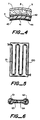
- Figure 4 is an enlarged and more detailed view of a part of Figure 3.
- Figure 5 is a diagrammatic plan view of another sheet heater which can be used in this invention; and
- Figure 6 is a diagrammatic cross-section through the strip heater used in Figure 5.
- The sheet heater must be positioned so that it is substantially separated from the antenna by a medium which is substantially transparent to thermal radiation, usually air, so that heat generated by the heater radiates from the heater through the medium and strikes the back surface of the antenna. Typically, the distance between the first surface of the heater and the back surface of the antenna is 3 to 6 inches (7.6 to 15.2 cm). In known methods in which an electrical resistance heater is placed in direct contact with an antenna, heating of the antenna takes place mainly or exclusively by conduction. In the present invention, by contrast, little or none of the heating of the antenna is the result of conduction and a substantial proportion, preferably at least 40%, particularly at least 60%, of the heating of the antenna is the result of radiation. The antenna is generally also heated by free convection from air (or other gas) which lies between the antenna and the heater. The air is preferably still air, i.e. any movement thereof is solely the result of convection currents.
- We have found that by heating the antenna in this way, the antenna is heated surprisingly uniformly even when the cooling effect of ice or snow is localized, and that as a result, improved signal reception and transmission, and compliance with the appropriate regulations, are achieved. This is apparently due to a combination of two factors. First, heat can be transferred to a localized cold spot not only from the portion of the heater directly opposite the cold spot, but also (though to a gradually decreasing extent) by the adjacent parts of the heater which can "view" the cold spot. Secondly, the heat transferred by radiation from the heater to the antenna is not directly proportional to the temperature difference between them (as it is if the heat is transferred by conduction) but is proportional to TH⁴-
T A⁴, where TH is the temperature of the first surface of the heater and TA is the temperature of the back surface of the antenna (in °K). - Another important advantage of the present invention stems from the fact that dish antennas generally comprise a plurality of ribs which extend from the back surface of the antenna. As a result, if an electrical resistance heater is to be placed in direct contact with the antenna, a large number of specially shaped and interconnected component heaters must be used, and they must contact substantially the whole of the antenna. When radiant heating is employed, as in the present invention, the heater can be positioned clear of the ribs, thus making it possible to use one or a relatively small number of sheet heaters, e.g. less than 8, for example 4 to 6, each of which has an easily manufactured shape, e.g. a rectangular shape. Furthermore, it is not necessary for the heater to cover the whole of the back surface of the antenna. The ratio of the area of the heater to the area of the back surface of the antenna (ignoring the ribs) should generally be at least 0.3, but it need not be (though of course it can be) as high as 1.0; thus the ratio is preferably 0.4 to 0.9, particularly 0.5 to 0.8.
- Direct physical contact between the antenna and the heater is preferably minimized, especially when the antenna comprises ribs of metal or other thermally conductive material, since heating of the antenna by conduction through the ribs tends to cause irregular heating, and consequent distortion, of the front surface. Thus it is preferred that at least 90%, particularly at least 95%, especially substantially 100%, of the first surface of the heater is exposed to the air (or other medium which separates the dish antenna and the heater). If the heater is secured to ribs on the back surface of the antenna, it is preferably secured to the ribs by fasteners which are composed of polymeric material or other material of low thermal conductivity, which are spaced apart from each other, and which preferably prevent direct contact between the heater and the ribs. Preferably, however, the heater is secured to a back shell which is secured to the dish antenna around the perimeter thereof. The back shell is preferably environmentally sealed to the antenna, to minimize heat losses.
- The first surface of the heater and/or the back surface of the dish antenna are preferably treated in some way which improves the emissivity thereof, for example by painting with a flat black paint. The second surface of the heater, on the other hand, is preferably such that its emissivity is low. Furthermore, the second surface is preferably substantially covered by thermal insulation material, eg. a foamed polymer, fiberglass or other void-containing polymeric material, either alone or backed by a metallic foil.
- Any form of sheet heater can be used in this invention providing that it radiates heat sufficiently uniformly to warm the antenna without causing substantial distortion thereof. For this purpose, the radiant thermal output preferably does not vary by more than ± 20%, particularly not more than ± 10%, from the average value, when the thermal load is the same at all points on the heater, i.e. when the antenna is at a uniform temperature. Preferred heaters comprise a resistive element which is in the form of a sheet having electrodes secured (directly or indirectly) thereto. Preferably each of the electrodes is also in the form of a sheet, eg. a metal foil, the resistive element lying between the electrodes so that the current passes normally through the resistive element; however, other electrode arrangements are also possible. Satisfactory heaters can also be made by combining one or more strip heaters with a sheet of metal, eg. aluminum, or other material of high thermal conductivity. The strip heater(s) can be secured to one surface of the metal sheet, the opposite face then serving as the radiant surface, or can be sandwiched between two metal sheets, or can be embedded in the sheet. The arrangement and spacing of the strip heater(s) should be such as to provide a sufficiently uniform radiant heat output. Thus one or more strip heaters can for example be arranged in serpentine fashion; or a plurality of strip heaters can for example be arranged parallel to each other, together with electrical bus connectors to feed power to the heaters.
- The heater is preferably self-regulating, ie. the higher the thermal load at any particular point on the heater (or in any particular zone which is small in comparison with the overall size of the heater), the higher the heat output of the heater at that point (or in that zone); this avoids overheating of the antenna in areas which are not being cooled by ice or snow, and results in remarkable temperature uniformity of the dish antenna, and consequent minimization of distortion of the antenna. The separation of the antenna and the self-regulating heater would be expected to result in a reduction of the sensitivity of the thermal output of the heater to the temperature of the antenna. In fact, however, the sensitivity is increased, and this apparently results from a combination of the self-regulating characteristic with the two factors discussed above (i.e. (1) a localized change in the temperature of the antenna is sensed not only by the portion of the heater directly opposite the change, but also by the adjacent parts of the heater, and (2) the heat transferred by radiation from the heater to the antenna is proportional to TH⁴-TA⁴).
- Preferred self-regulating heaters for use in this invention comprise a PTC (positive temperature coefficient of resistance) conductive polymer composition which forms part or all of the resistive heating element or which acts as a control element for a ZTC (zero temperature coefficient) resistive heating element ie. a heating element whose thermal output is substantially independent of temperature, which may be composed of a conductive polymer composition or other material, e.g. a Nichrome or other resistive heating wire. Self-regulation through other PTC materials or through other means (e.g. the skin effect or the Curie point effect) is also possible.
- If a self-regulating heater is not used, one or more thermostats may be used to control a ZTC heater.
- For details of heaters, including self-regulating heaters, and conductive polymer compositions, refer ence may be made to U.S. Patents Nos. 3,218,384, 3,296,364, 4,072,848, 4,117,312, 4,304,987, 4,330,703, 4,425,497, 4,429,216, 4,534,889 and 4,560,498, and European Patent Publication Nos. 158,410 (MP0897), 197,759 (MP1039), 223,404 (MP1090), 227,405 (MP1034), 231,068 (MP1095&1100).
- Referring now to the drawing, Figures 1 and 2 show a dish antenna 1 having a concave front surface 11 and a
convex back surface 12 and a plurality ofribs 13 extending from the back surface. An electrical heater comprising fourrectangular panels polymeric straps 6. - Figure 3 is similar to Figure 2, but shows an assembly further comprising a back shell 7, which is environmentally sealed to the periphery of dish antenna 1; the
heater panels ribs 13, and alayer 8 of fiberglass insulation secured to ametal foil 9 lies between the heater and the insulation. - As shown in the detailed view of Figure 4, the heater comprises
metal foil electrodes resistive heating element 43 sandwiched between them. The front surface of the heater has acoating 44 of flat black paint thereon. - Figure 5 shows an alternative form of sheet heater for use in the invention which comprises a metal, eg. aluminum,
plate 100 having astrip heater 101 secured one surface thereof. The first (radiant) surface of the heater is the opposite face. Figure 6 is a cross-section through a preferred strip heater which compriseswire electrodes strip 63 of a PTC conductive polymer, andpolymeric insulation 64 surrounding thestrip 63. - The invention is further illustrated by the following Example.
- A PTC conductive polymer powder was prepared by mixing 56% by weight of Marlex 50100 (high density polyethylene made by Phillips Petroleum), 43% by weight of Statex GH (carbon black made by Columbian Chemicals), and 1% by weight of an antioxidant in a Banbury mixer. The resulting compound was irradiated to a dose of 50 Mrads in a 3MeV electron beam and pulverized until all the particles were smaller than 187 micrometers (80 mesh). This PTC powder was tumble-blended with an equal weight of FA750 (high density polyethylene made by USI Chemicals), and the blend was extruded into a 12 inch by 0.040 inch (30.5 × 0.10 cm) sheet.
- Using a belt laminator set at 400°F (204°C), the sheet was laminated on each side with 0.001 inch (0.0025 cm) TEX-1 foil (nickel/zinc passivated electro deposited copper made by Yates).
- A heater for a 1.8 meter diameter antenna was made as follows. The laminated sheet was trimmed into five approximately 10 by 60 inch (25.4 by 152.4 cm) panels. Electrical busbars were attached to the two surfaces of each panel by soldering 0.020 by 0.5 inch (0.05 × 1.27 cm) copper strips terminated with 16 AWG copper conductor onto the copper foil. Adjacent panels were electrically connected in parallel using a standard connection suitable for attachment to a 120V power source. The panels and connections were electrically insulated by covering all surfaces completely with adhesive-backed Mylar tape. The first surface of the resulting heater (ie. the radiant surface) was then painted with flat black paint (Krylon) to enhance its thermal emissivity.
- The heater was fastened with plastic straps to the back surface of the dish antenna, avoiding direct contact with all structural ribs. A back shell for the antenna was mated to the antenna, placing polyurethane foam between the back of the heater and the back shell to reduce heat losses.
Claims (10)
- A dish antenna assembly which comprises(1) a dish antenna (1) having a concave front surface (11) and a convex back surface (12); and(2) an electrical heater (2,3,4,5) in the form of a sheet having a first surface and an opposite second surface,
the assembly being characterised in that the first surface of the heater (2,3,4,5) is adjacent to the back surface of the antenna (1) but separated therefrom by a medium, typically air, which is substantially transparent to thermal radiation, whereby heat generated by the heater (2,3,4,5) radiates from the first surface and strikes the back surface of the antenna (1), the assembly being such that at least 40% of the heat received by the dish antenna (1) is radiant heat. - An assembly according to claim 1 wherein substantially all of the first surface of the heater (2,3,4,5) is contacted by the medium which separates the dish antenna (1) and the heater (2,3,4,5).
- An assembly according to claim 1 or 2 wherein the antenna (1) comprises a plurality of ribs (13) which extend from the back surface thereof and the heater (2,3,4,5) is secured to the ribs (13) by fastening members (6) which are composed of polymeric material and which are spaced apart from each other.
- An assembly according to any one of the preceding claims which comprises a back shell (7) which is secured to the dish antenna (1) around the perimeter thereof and to which the heater (2,3,4,5) is secured.
- An assembly according to any one of the preceding claims which comprises (a) a back shell (7) which is environmentally sealed to the dish antenna (1), and (b) thermal insulation material (8) which substantially covers the second surface of the heater (2,3,4,5).
- An assembly according to anyone of the preceding claims wherein the heater (2,3,4,5) is a self-regulating heater, preferably a heater which comprises two metal foil electrodes (41,42) and a resistive heating element (43) which is composed of a conductive polymer element exhibiting PTC behavior and is in the form of a sheet lying between the foil electrodes (41, 42).
- An assembly according to any one of the preceding claims wherein the ratio of the area of the first surface of the heater (2,3,4,5) to the area of the back surface of the dish antenna (1) is at least 0.3, preferably 0.4 to 0.9, especially 0.5 to 0.8.
- An assembly according to any one of the preceding claims which comprises a plurality of heaters (2,3,4,5) which are connected in parallel and at least one of which comprises a resistive heating element which is in the form of substantially rectangular sheet.
- An assembly according to any one of the preceding claims, wherein the heater comprises a self-regulating strip heater (101) arranged in serpentine form, the strip heater being secured to a metal sheet (100) or being sandwiched between two metal sheets.
- An assembly according to claim 9, wherein the self-regulating strip heater (101) comprises wire electrodes (61,62) embedded in a strip (63) of a PTC conductive polymer.
Priority Applications (1)
| Application Number | Priority Date | Filing Date | Title |
|---|---|---|---|
| AT87308610T ATE79487T1 (en) | 1986-09-30 | 1987-09-29 | PARABOTIC AERIAL WITH HEATER. |
Applications Claiming Priority (2)
| Application Number | Priority Date | Filing Date | Title |
|---|---|---|---|
| US91329086A | 1986-09-30 | 1986-09-30 | |
| US913290 | 1986-09-30 |
Publications (2)
| Publication Number | Publication Date |
|---|---|
| EP0268362A1 EP0268362A1 (en) | 1988-05-25 |
| EP0268362B1 true EP0268362B1 (en) | 1992-08-12 |
Family
ID=25433136
Family Applications (1)
| Application Number | Title | Priority Date | Filing Date |
|---|---|---|---|
| EP87308610A Expired - Lifetime EP0268362B1 (en) | 1986-09-30 | 1987-09-29 | Heated dish antennas |
Country Status (6)
| Country | Link |
|---|---|
| EP (1) | EP0268362B1 (en) |
| JP (1) | JPS6390204A (en) |
| KR (1) | KR880004597A (en) |
| AT (1) | ATE79487T1 (en) |
| CA (1) | CA1292800C (en) |
| DE (1) | DE3781096T2 (en) |
Cited By (1)
| Publication number | Priority date | Publication date | Assignee | Title |
|---|---|---|---|---|
| EP4175409A1 (en) * | 2021-11-01 | 2023-05-03 | Amphenol Thermometrics, Inc. | Antenna heater and methods for preventing ice formation on electromagnetic wave antennas |
Families Citing this family (7)
| Publication number | Priority date | Publication date | Assignee | Title |
|---|---|---|---|---|
| EP0326744A3 (en) * | 1987-11-25 | 1989-08-23 | Andrew Corporation | Anti-icing and de-icing system for reflector-type microwave antennas |
| GB2234117A (en) * | 1989-07-19 | 1991-01-23 | David Scott | Satellite reception window |
| WO1997040646A1 (en) * | 1996-04-19 | 1997-10-30 | Thermion Systems International | Method for heating the surface of an antenna dish |
| US5932124A (en) * | 1996-04-19 | 1999-08-03 | Thermion Systems International | Method for heating a solid surface such as a floor, wall, or countertop surface |
| US7747319B2 (en) | 2006-03-17 | 2010-06-29 | Zoll Medical Corporation | Automated resuscitation device with ventilation sensing and prompting |
| US9398642B2 (en) | 2012-10-22 | 2016-07-19 | Thales Canada Inc | Removable heater for communication antenna |
| DE202017002725U1 (en) | 2017-05-23 | 2017-06-13 | Dynamic Solar Systems Ag | Heating panel with printed heating |
Family Cites Families (5)
| Publication number | Priority date | Publication date | Assignee | Title |
|---|---|---|---|---|
| DE2163168A1 (en) * | 1971-01-18 | 1972-10-05 | Inst Fuer Nachrichtentechnik | Arrangement for heating a cover of a parabolic antenna attached in the direction of radiation |
| FR2426343A1 (en) * | 1978-05-16 | 1979-12-14 | Bony Gilbert | Plastics sandwich telecommunication parabolic reflector - has integral deicing heating element laid on honeycomb structure |
| US4304987A (en) * | 1978-09-18 | 1981-12-08 | Raychem Corporation | Electrical devices comprising conductive polymer compositions |
| DE3030799A1 (en) * | 1979-08-17 | 1981-03-26 | Raychem Corp., Menlo Park, Calif. | ARRANGEMENT WITH COLD-CONDUCTING RADIATOR |
| DE3525488A1 (en) * | 1985-07-17 | 1987-01-29 | Dynamit Nobel Ag | Surface reflector antenna which can be heated electrically |
-
1987
- 1987-09-29 EP EP87308610A patent/EP0268362B1/en not_active Expired - Lifetime
- 1987-09-29 DE DE8787308610T patent/DE3781096T2/en not_active Expired - Fee Related
- 1987-09-29 AT AT87308610T patent/ATE79487T1/en active
- 1987-09-29 CA CA000548071A patent/CA1292800C/en not_active Expired - Lifetime
- 1987-09-29 KR KR870010821A patent/KR880004597A/en not_active Withdrawn
- 1987-09-29 JP JP62245729A patent/JPS6390204A/en active Pending
Cited By (1)
| Publication number | Priority date | Publication date | Assignee | Title |
|---|---|---|---|---|
| EP4175409A1 (en) * | 2021-11-01 | 2023-05-03 | Amphenol Thermometrics, Inc. | Antenna heater and methods for preventing ice formation on electromagnetic wave antennas |
Also Published As
| Publication number | Publication date |
|---|---|
| DE3781096D1 (en) | 1992-09-17 |
| CA1292800C (en) | 1991-12-03 |
| ATE79487T1 (en) | 1992-08-15 |
| EP0268362A1 (en) | 1988-05-25 |
| KR880004597A (en) | 1988-06-07 |
| JPS6390204A (en) | 1988-04-21 |
| DE3781096T2 (en) | 1993-03-11 |
Similar Documents
| Publication | Publication Date | Title |
|---|---|---|
| US4866452A (en) | Heated dish antennas | |
| EP0038717B1 (en) | Electrical devices containing ptc elements | |
| US4314230A (en) | Devices comprising conductive polymers | |
| US4882466A (en) | Electrical devices comprising conductive polymers | |
| US4904850A (en) | Laminar electrical heaters | |
| CA1292800C (en) | Heated dish antennas | |
| EP0716559B1 (en) | Planar heating device for use with mirrors | |
| US5938957A (en) | Planar heating device for a mirror and method of producing the same | |
| US5898407A (en) | Motor vehicle with antenna window with improved radiation and reception characteristics | |
| EP0356087A2 (en) | Positive temperature coefficient heater | |
| US5806102A (en) | Face shield for helmet | |
| EP0203709B1 (en) | Attenuation of microwave signals | |
| ES2020017A6 (en) | Thermally-emissive, weaponry target, training aid or arc designator structure. | |
| CN210381343U (en) | Electric heating film and electric heater provided with same | |
| EP0850548A1 (en) | Electric heating devices and elements | |
| GB2041859A (en) | Mirror for Motor Vehicles | |
| GB2128415A (en) | Antenna and method of manufacture thereof | |
| EP0397685B1 (en) | Laminar electrical heaters | |
| JP2680362B2 (en) | Antenna device | |
| US6664513B1 (en) | Wall-mounted mirror heated by convection and radiation | |
| AU2079200A (en) | A low temperature low voltage heating device | |
| JPH088043A (en) | Soaking device | |
| GB2064927A (en) | Heatable mirror | |
| JPH032968Y2 (en) | ||
| JP3641023B2 (en) | Parabolic antenna snow melting heater |
Legal Events
| Date | Code | Title | Description |
|---|---|---|---|
| PUAI | Public reference made under article 153(3) epc to a published international application that has entered the european phase |
Free format text: ORIGINAL CODE: 0009012 |
|
| 17P | Request for examination filed |
Effective date: 19871029 |
|
| AK | Designated contracting states |
Kind code of ref document: A1 Designated state(s): AT BE CH DE ES FR GB GR IT LI NL SE |
|
| 17Q | First examination report despatched |
Effective date: 19901207 |
|
| GRAA | (expected) grant |
Free format text: ORIGINAL CODE: 0009210 |
|
| AK | Designated contracting states |
Kind code of ref document: B1 Designated state(s): AT BE CH DE ES FR GB GR IT LI NL SE |
|
| PG25 | Lapsed in a contracting state [announced via postgrant information from national office to epo] |
Ref country code: IT Free format text: LAPSE BECAUSE OF FAILURE TO SUBMIT A TRANSLATION OF THE DESCRIPTION OR TO PAY THE FEE WITHIN THE PRESCRIBED TIME-LIMIT;WARNING: LAPSES OF ITALIAN PATENTS WITH EFFECTIVE DATE BEFORE 2007 MAY HAVE OCCURRED AT ANY TIME BEFORE 2007. THE CORRECT EFFECTIVE DATE MAY BE DIFFERENT FROM THE ONE RECORDED. Effective date: 19920812 Ref country code: SE Free format text: THE PATENT HAS BEEN ANNULLED BY A DECISION OF A NATIONAL AUTHORITY Effective date: 19920812 Ref country code: FR Effective date: 19920812 Ref country code: GR Free format text: LAPSE BECAUSE OF FAILURE TO SUBMIT A TRANSLATION OF THE DESCRIPTION OR TO PAY THE FEE WITHIN THE PRESCRIBED TIME-LIMIT Effective date: 19920812 Ref country code: AT Effective date: 19920812 Ref country code: BE Effective date: 19920812 Ref country code: NL Effective date: 19920812 |
|
| REF | Corresponds to: |
Ref document number: 79487 Country of ref document: AT Date of ref document: 19920815 Kind code of ref document: T |
|
| REF | Corresponds to: |
Ref document number: 3781096 Country of ref document: DE Date of ref document: 19920917 |
|
| PG25 | Lapsed in a contracting state [announced via postgrant information from national office to epo] |
Ref country code: ES Free format text: LAPSE BECAUSE OF FAILURE TO SUBMIT A TRANSLATION OF THE DESCRIPTION OR TO PAY THE FEE WITHIN THE PRESCRIBED TIME-LIMIT Effective date: 19921123 |
|
| EN | Fr: translation not filed | ||
| NLV1 | Nl: lapsed or annulled due to failure to fulfill the requirements of art. 29p and 29m of the patents act | ||
| PLBE | No opposition filed within time limit |
Free format text: ORIGINAL CODE: 0009261 |
|
| STAA | Information on the status of an ep patent application or granted ep patent |
Free format text: STATUS: NO OPPOSITION FILED WITHIN TIME LIMIT |
|
| 26N | No opposition filed | ||
| REG | Reference to a national code |
Ref country code: CH Ref legal event code: PUE Owner name: RAYCHEM CORPORATION (A CALIFORNIA CORPORATION) -DA Ref country code: CH Ref legal event code: NV Representative=s name: KATZAROV S.A. |
|
| REG | Reference to a national code |
Ref country code: GB Ref legal event code: 732E |
|
| PGFP | Annual fee paid to national office [announced via postgrant information from national office to epo] |
Ref country code: GB Payment date: 19981001 Year of fee payment: 12 |
|
| PGFP | Annual fee paid to national office [announced via postgrant information from national office to epo] |
Ref country code: DE Payment date: 19981005 Year of fee payment: 12 |
|
| PGFP | Annual fee paid to national office [announced via postgrant information from national office to epo] |
Ref country code: CH Payment date: 19981009 Year of fee payment: 12 |
|
| PG25 | Lapsed in a contracting state [announced via postgrant information from national office to epo] |
Ref country code: GB Free format text: LAPSE BECAUSE OF NON-PAYMENT OF DUE FEES Effective date: 19990929 |
|
| PG25 | Lapsed in a contracting state [announced via postgrant information from national office to epo] |
Ref country code: CH Free format text: LAPSE BECAUSE OF NON-PAYMENT OF DUE FEES Effective date: 19990930 Ref country code: LI Free format text: LAPSE BECAUSE OF NON-PAYMENT OF DUE FEES Effective date: 19990930 |
|
| REG | Reference to a national code |
Ref country code: CH Ref legal event code: PL |
|
| GBPC | Gb: european patent ceased through non-payment of renewal fee |
Effective date: 19990929 |
|
| PG25 | Lapsed in a contracting state [announced via postgrant information from national office to epo] |
Ref country code: DE Free format text: LAPSE BECAUSE OF NON-PAYMENT OF DUE FEES Effective date: 20000701 |