EP0267798A2 - Multiphase valve testing - Google Patents
Multiphase valve testing Download PDFInfo
- Publication number
- EP0267798A2 EP0267798A2 EP87310024A EP87310024A EP0267798A2 EP 0267798 A2 EP0267798 A2 EP 0267798A2 EP 87310024 A EP87310024 A EP 87310024A EP 87310024 A EP87310024 A EP 87310024A EP 0267798 A2 EP0267798 A2 EP 0267798A2
- Authority
- EP
- European Patent Office
- Prior art keywords
- test
- chamber
- fluid
- pressure
- relief valve
- Prior art date
- Legal status (The legal status is an assumption and is not a legal conclusion. Google has not performed a legal analysis and makes no representation as to the accuracy of the status listed.)
- Granted
Links
- 238000012360 testing method Methods 0.000 title claims abstract description 150
- 239000012530 fluid Substances 0.000 claims abstract description 70
- 238000004891 communication Methods 0.000 claims abstract description 6
- 239000007788 liquid Substances 0.000 claims description 9
- 238000000034 method Methods 0.000 claims description 6
- 238000013022 venting Methods 0.000 claims description 5
- 230000006835 compression Effects 0.000 claims description 3
- 238000007906 compression Methods 0.000 claims description 3
- 238000010438 heat treatment Methods 0.000 claims description 3
- 238000007789 sealing Methods 0.000 claims description 3
- 239000007791 liquid phase Substances 0.000 claims description 2
- 239000012808 vapor phase Substances 0.000 claims 4
- 230000003247 decreasing effect Effects 0.000 claims 3
- 238000010998 test method Methods 0.000 claims 2
- IJGRMHOSHXDMSA-UHFFFAOYSA-N Atomic nitrogen Chemical compound N#N IJGRMHOSHXDMSA-UHFFFAOYSA-N 0.000 description 6
- 230000009467 reduction Effects 0.000 description 4
- 238000006073 displacement reaction Methods 0.000 description 3
- 229910052757 nitrogen Inorganic materials 0.000 description 3
- 238000012856 packing Methods 0.000 description 3
- 238000007654 immersion Methods 0.000 description 2
- 238000012544 monitoring process Methods 0.000 description 2
- 230000004044 response Effects 0.000 description 2
- XLYOFNOQVPJJNP-UHFFFAOYSA-N water Substances O XLYOFNOQVPJJNP-UHFFFAOYSA-N 0.000 description 2
- 238000013459 approach Methods 0.000 description 1
- 230000005494 condensation Effects 0.000 description 1
- 238000009833 condensation Methods 0.000 description 1
- 239000007792 gaseous phase Substances 0.000 description 1
- 230000003993 interaction Effects 0.000 description 1
- 238000012423 maintenance Methods 0.000 description 1
- 238000012986 modification Methods 0.000 description 1
- 230000004048 modification Effects 0.000 description 1
- 210000002445 nipple Anatomy 0.000 description 1
- 239000012071 phase Substances 0.000 description 1
- 230000008569 process Effects 0.000 description 1
- 231100000331 toxic Toxicity 0.000 description 1
- 230000002588 toxic effect Effects 0.000 description 1
Images


Classifications
-
- G—PHYSICS
- G01—MEASURING; TESTING
- G01M—TESTING STATIC OR DYNAMIC BALANCE OF MACHINES OR STRUCTURES; TESTING OF STRUCTURES OR APPARATUS, NOT OTHERWISE PROVIDED FOR
- G01M3/00—Investigating fluid-tightness of structures
- G01M3/02—Investigating fluid-tightness of structures by using fluid or vacuum
- G01M3/26—Investigating fluid-tightness of structures by using fluid or vacuum by measuring rate of loss or gain of fluid, e.g. by pressure-responsive devices, by flow detectors
- G01M3/28—Investigating fluid-tightness of structures by using fluid or vacuum by measuring rate of loss or gain of fluid, e.g. by pressure-responsive devices, by flow detectors for pipes, cables or tubes; for pipe joints or seals; for valves ; for welds
- G01M3/2876—Investigating fluid-tightness of structures by using fluid or vacuum by measuring rate of loss or gain of fluid, e.g. by pressure-responsive devices, by flow detectors for pipes, cables or tubes; for pipe joints or seals; for valves ; for welds for valves
Definitions
- This invention generally relates to apparatus and a method for testing valves, and more particularly, for set point and seat leakage testing of pressure relief valves with selected fluids in selected phases.
- the present invention in its broad form resides in portable apparatus for testing a pressure relief valve by simulating pressure relief conditions, said apparatus comprising: a housing defining a substantially cylindrical internal chamber; a piston member slidable in said internal chamber and dividing said chamber into a test chamber and a pressurizing chamber respectively on opposite sides of said piston member; means for sealingly attaching the relief valve to be tested to one end of the housing with the relief valve in communication with the test chamber; characterized by: controlled inlet means for selectively introducing into and sealing within the test chamber and relief valve a fixed amount of a selected test fluid; means for measuring the pressure of the test fluid in the test chamber; and controlled pressurizing means for introducing a pressurizing fluid into said pressurizing chamber to increase the pressure of said test fluid through movement of said piston member until said relief valve actuates, whereby the pressure measuring means provides an indication of the pressure at which the relief valve actuated with the selected test fluid.
- a relief valve is tested using a test device which includes a housing defining an internal chamber which is divided into a test chamber and a pressurizing chamber by piston means.
- the piston means includes a main piston which forms an end wall of the test chamber, a translator piston which forms an end wall of the pressurizing chamber, and a spring pack in the form of a helical compression spring between the two pistons.
- the relief valve to be tested is bolted to an adapter plate having a hole pattern adapted to receive various sizes of relief valves with the inlet of the relief valve in communication with the test chamber.
- a selected test medium is introduced into the test chamber and relief valve through an inlet pipe while air is vented through a diametrically displaced vent pipe.
- an inlet valve in the inlet line and a vent valve in the vent line are closed, and pressurizing fluid is introduced into the pressurizing chamber. Movement of the translator piston in response to the introduction of pressurizing fluid into the pressurizing chamber compresses the spring pack to load the main piston. The pressure in the test chamber is increased by increasing the pressure in the pressurizing chamber until the relief valve actuates. The set point of the relief valve is checked against the pressure in the test chamber at which the valve actuates as indicated by a pressure gauge, preferably connected in the vent line.
- an electric immersion heater in the test chamber heats the fluid medium to the desired temperature.
- the temperature of the test fluid in the liquid state is increased with system pressure set lower than the desired test pressure, at a pressure just above, but close to, the pressure required to maintain the test fluid in the liquid state at the desired test temperature.
- system pressure is rapidly reduced causing the liquid to flash into vapor.
- this rapid reduction in pressure is achieved through a rapid increase in the volume of the test chamber induced by a reduction in the pressure of the pressurizing fluid.
- the pressure is quickly built up to the desired test pressure by again increasing the pressure of the pressurizing fluid. When the pressure has stabilized it is then slowly increased further until the relief valve actuates.
- the apparatus and method of the invention offer many advantages in the testing of relief valves.
- a relief valve may be tested using different fluids in one set up. Testing can be conducted at various fluid temperatures and in their gaseous or liquid phase. Discharge of test fluid is minimized so that toxic fluids can be safely handled and vented.
- the device is portable and can be used to test more than one size valve using the same fixture. Furthermore, no correlation factors are required. The actual data can be recorded as representative of valve behavior.
- the valve testing device 1 of the invention comprises a cylindrical housing 3 having a longitudinal bore 5 which defines an elongated chamber 7.
- the elongated chamber 7 is closed at one end by an end plate 9 secured by nuts and bolts 11 to flange 13 welded at 15 to the housing 3.
- Another flange 17 is welded at 19 to the other end of the housing 3, and an adapter plate 21 is secured to this flange by studs and nuts 23 (see Figure 3,).
- the adapter plate 21 is provided with bolt holes 25 arranged in a pattern which accepts various sizes of relief valves.
- a relief valve 27 is bolted by bolts to the adapter plate 21 for testing.
- a piston assembly 31 slidable in the bore 5 of the housing divides the elongated chamber 7 into a test chamber 33 and a pressurizing chamber 35.
- This piston assembly 31 includes a main piston 37 forming an end wall of the test chamber 33 and a translator piston 39 which forms one end wall of the pressurizing chamber 35. Between the main piston 37 and translator piston 39 is a spring pack 41 comprising a helical compression spring.
- An inlet pipe 43 and vent pipe 45 penetrate the wall of housing 3 at diametrically opposed locations for feeding and venting, respectively, the test-chamber 33.
- An inlet valve 47 and vent valve 49 selectively block off the inlet pipe 43 and vent pipe 45 respectively.
- Connected to the vent pipe 45 are pressure measuring accessories in the form of pressure gauge 51 for direct reading of the test chamber pressure and pressure transducer 53 for transmitting pressure signals to a pressure control device (not shown).
- Four equiangularly spaced travel stop buttons 55 (only three shown) extending inward through the wall of the housing 3 limit the travel of the piston assembly 31 in the direction of the test chamber 33 so that the inlet and vent pipes are not blocked by the piston.
- Primary leak tightness for the main piston is provided by the pair of "O" ring seals 57 seated in annular grooves 59 in the piston.
- a secondary or back-up seal is provided by a ;pair of packing rings 61 seated in a groove 63 and held in place by a packing flange 65 and packing bolts 67.
- the translator piston 39 is sealed by "O" ring seals 69 seated in grooves 71.
- the end plate 9 is sealed against flange 13 by gasket 73.
- the adapter plate 21 is sealed against flange 71 by gasket 75.
- the space 77 between pistons 37 and 39 is vented by orifice 79 through which any leakage from the test chamber 33 or pressurizing chamber 35 is removed.
- An electric immersion heater 85 extends through the housing 3 into the test-chamber 33 for heating the test medium for certain tests as discussed below.
- Thermocouples 87 are also provided in the test chamber for measuring the temperature of the test medium.
- a nipple 89 is centrally located in endplate 9 for connecting a hose 91 for admitting and venting a pressurizing fluid supplied by a pressurized fluid source 93 into the pressurizing chamber 35 to provide the motive force to pressurize test fluid in the test-chamber 33.
- a relief valve 27 to be tested is bolted to the adapter plate 21 as shown in Figure 3 with the inlet of the valve in communication with the test chamber 33 through a central bore 93 in the adapter plate.
- the test device can be supported with the relief valve in any orientation desired such as by the supports 95 in Figure 3.
- the desired test fluid is admitted into the test chamber 33 and relief valve 27 through inlet pipe 43 by opening inlet valve 47. Any air in test chamber 33 is vented out through vent pipe 45 by opening vent valve 49.
- the test device 1 may be rotated to assure that all the air if removed. Once the test chamber 33 is filled with test fluid, the inlet pipe 43 and vent pipe 45 are blocked by closing valves 47 and 49 respectively.
- a high pressure fluid (such as air, water or oil) is introduced into pressurizing chamber 35 and bears against the translator piston 39 causing it to move.
- the motion of the translator piston 39 compresses the spring pack 41 which in turn loads the main piston.
- the main piston compresses the test fluid trapped in test chamber 33.
- the pressure of the test fluid is increased until the relief valve set point pressure is reached and the valve pops.
- the heaters 85 are turned on and the temperature of the test fluid is controlled by means of thermocouple 87 output.
- Thermal pressurization is minimized by the fact that the spring pack 41 compresses a pressure in the test chamber 33 increases, thus reducing the likelihood of a thermally induced pressure build up in the chamber.
- Testing proceeds by increasing the pressure of the hydraulic fluid in pressurizing chamber 35 until the valve test pressure is reached and the valve 27 pops. If the temperature is increased to the point where the rod 81 seats against the translator piston 39, further increase in the pressure in the test chamber 33 can be precluded by utilizing a constant pressure pressurized fluid source 92 for supplying fluid to the pressurizing chamber 35.
- translator piston 39 could alternatively be fixed to the main piston 37 such as by a rod 81 secured to both pistons.
- a constant pressure source of pressurized fluid should be used to minimize pressure build up in the test chamber during hot testing.
- the temperature of the fluid in the liquid state is increased with system pressure set lower than the desired test pressure, at a pressure just above, but close to, the pressure required to maintain the test fluid in the liquid state at the desired test temperature.
- system pressure set lower than the desired test pressure, at a pressure just above, but close to, the pressure required to maintain the test fluid in the liquid state at the desired test temperature.
- the test fluid pressure is set at 2,300 psi which has a saturation temperature of 655.89 degrees F. Heat is applied to the test fluid until the desired temperature of 650 degrees F is reached. Once this temperature is reached, the test pressure is suddenly reduced (for example, from 2,300 psi to 1,000 psi) causing the test fluid to flash into a vapor state.
- test pressure is suddenly reduced by increasing the volume of the test chamber 33 through movement of the piston assembly 31 in response to a sudden reduction in the pressure of the pressurizing fluid supplied to the presssurizing chamber 35.
- the test pressure is quickly built up to the test condition (i.e., 2,500 psi) by increasing the pressure of the hydraulic fluid supplied to chamber 35.
- the desired pressure is reached, it is allowed to stabilize in accordance with the desired test instructions. Since condensation from a vapor state to a liquid state condition is a slow thermodynamic process, the test medium will remain in a vapor state for a considerable time allowing sufficient time for testing to be conducted. By gradually increasing the pressure, the valve will pop at its set point in the desired test medium.
- thermocouples 87 and pressure transducers 53 Pressures and temperatures are monitored by means of the thermocouples 87 and pressure transducers 53.
- the adapter plate 21 in addition to providing means to adapt the device 1 to various relief valves 27 also provides a means to mount and move the assembled device such that it can be positioned in a most convenient way for the test.
Landscapes
- Physics & Mathematics (AREA)
- General Physics & Mathematics (AREA)
- Testing Of Devices, Machine Parts, Or Other Structures Thereof (AREA)
- Investigating Strength Of Materials By Application Of Mechanical Stress (AREA)
- Safety Valves (AREA)
Abstract
Description
- This invention generally relates to apparatus and a method for testing valves, and more particularly, for set point and seat leakage testing of pressure relief valves with selected fluids in selected phases.
- Set point testing of relief valves is required by the American Society of Mechanical Engineers (Sections III, VIII) to assure that vessels, boilers and pipelines are not over pressurized. To accomplish this, two schemes are generally used, viz:
- (1) one approach is to remove the valve to be tested from the protected equipment and test it in a shop with water, nitrogen or steam, as available. Nitrogen is commonly used because it is generally available.
- (2) another technique is to leave the relief valve in place on the protected equipment and to install on top of the valve an assist device, typically pneumatic or hydraulic powered, that will aid the valve to open. By monitoring system conditions in the output of the assist device, it is possible in turn to assess the set point of the relief valve.
- While the above schemes are generally acceptable, there is always a desire among maintenance and operations people, to test relief valves for set point and leakage in the actual medium and conditions in which they are used to confirm their operational readiness. For example, set point testing of relief valves used in steam service with nitrogen is permissible, but there is no reliable correlation that converts the test results in one fluid medium to another. Similarly, the use of power assist devices introduces some uncertainty in data reduction in terms of the interaction of the displacements of many interacting valve parts on the estimated set point. Since the set point is back calculated when power assist devices are used, the accuracy of the final result depends upon the precision of the recorded variables. Thus, while the present test schemes are acceptable, they can still be improved upon.
- The present invention in its broad form resides in portable apparatus for testing a pressure relief valve by simulating pressure relief conditions, said apparatus comprising: a housing defining a substantially cylindrical internal chamber; a piston member slidable in said internal chamber and dividing said chamber into a test chamber and a pressurizing chamber respectively on opposite sides of said piston member; means for sealingly attaching the relief valve to be tested to one end of the housing with the relief valve in communication with the test chamber; characterized by: controlled inlet means for selectively introducing into and sealing within the test chamber and relief valve a fixed amount of a selected test fluid; means for measuring the pressure of the test fluid in the test chamber; and controlled pressurizing means for introducing a pressurizing fluid into said pressurizing chamber to increase the pressure of said test fluid through movement of said piston member until said relief valve actuates, whereby the pressure measuring means provides an indication of the pressure at which the relief valve actuated with the selected test fluid.
- As described herein, a relief valve is tested using a test device which includes a housing defining an internal chamber which is divided into a test chamber and a pressurizing chamber by piston means. Preferably, the piston means includes a main piston which forms an end wall of the test chamber, a translator piston which forms an end wall of the pressurizing chamber, and a spring pack in the form of a helical compression spring between the two pistons. The relief valve to be tested is bolted to an adapter plate having a hole pattern adapted to receive various sizes of relief valves with the inlet of the relief valve in communication with the test chamber. A selected test medium is introduced into the test chamber and relief valve through an inlet pipe while air is vented through a diametrically displaced vent pipe. Once the test chamber and relief valve are filled with the selected test medium, an inlet valve in the inlet line and a vent valve in the vent line are closed, and pressurizing fluid is introduced into the pressurizing chamber. Movement of the translator piston in response to the introduction of pressurizing fluid into the pressurizing chamber compresses the spring pack to load the main piston. The pressure in the test chamber is increased by increasing the pressure in the pressurizing chamber until the relief valve actuates. The set point of the relief valve is checked against the pressure in the test chamber at which the valve actuates as indicated by a pressure gauge, preferably connected in the vent line.
- If a hot liquid test is desired, an electric immersion heater in the test chamber heats the fluid medium to the desired temperature. If vapor testing is desired, the temperature of the test fluid in the liquid state is increased with system pressure set lower than the desired test pressure, at a pressure just above, but close to, the pressure required to maintain the test fluid in the liquid state at the desired test temperature. Once the desired temperature is reached, system pressure is rapidly reduced causing the liquid to flash into vapor. Preferably, this rapid reduction in pressure is achieved through a rapid increase in the volume of the test chamber induced by a reduction in the pressure of the pressurizing fluid. Following flashing of the test fluid to the vapor state, the pressure is quickly built up to the desired test pressure by again increasing the pressure of the pressurizing fluid. When the pressure has stabilized it is then slowly increased further until the relief valve actuates.
- The apparatus and method of the invention offer many advantages in the testing of relief valves. With the invention, a relief valve may be tested using different fluids in one set up. Testing can be conducted at various fluid temperatures and in their gaseous or liquid phase. Discharge of test fluid is minimized so that toxic fluids can be safely handled and vented. The device is portable and can be used to test more than one size valve using the same fixture. Furthermore, no correlation factors are required. The actual data can be recorded as representative of valve behavior.
- A more detailed understanding of the invention may be had from the following description of a preferred embodiment, given by way of example, and to be understood in conjunction with the following drawing wherein:
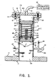
- Figure 1 is an inverted longitudinal section through the relief valve test device according to the invention;
- Figure 2 is a plan view of the adapter plate by which relief valves of varying sizes may be secured to the device of Figure 1; and
- Figure 3 is an elevation view of the test device of Figure 1 with a relief valve secured thereto for testing.
- As shown in the Figures the valve testing device 1 of the invention comprises a
cylindrical housing 3 having alongitudinal bore 5 which defines anelongated chamber 7. Theelongated chamber 7 is closed at one end by anend plate 9 secured by nuts and bolts 11 to flange 13 welded at 15 to thehousing 3. Anotherflange 17 is welded at 19 to the other end of thehousing 3, and anadapter plate 21 is secured to this flange by studs and nuts 23 (see Figure 3,). As illustrated in Figure 2, theadapter plate 21 is provided withbolt holes 25 arranged in a pattern which accepts various sizes of relief valves. As shown in Figure 3, arelief valve 27 is bolted by bolts to theadapter plate 21 for testing. - A
piston assembly 31 slidable in thebore 5 of the housing divides theelongated chamber 7 into atest chamber 33 and a pressurizingchamber 35. Thispiston assembly 31 includes amain piston 37 forming an end wall of thetest chamber 33 and atranslator piston 39 which forms one end wall of the pressurizingchamber 35. Between themain piston 37 andtranslator piston 39 is aspring pack 41 comprising a helical compression spring. - An
inlet pipe 43 andvent pipe 45 penetrate the wall ofhousing 3 at diametrically opposed locations for feeding and venting, respectively, the test-chamber 33. An inlet valve 47 andvent valve 49 selectively block off theinlet pipe 43 andvent pipe 45 respectively. Connected to thevent pipe 45 are pressure measuring accessories in the form ofpressure gauge 51 for direct reading of the test chamber pressure andpressure transducer 53 for transmitting pressure signals to a pressure control device (not shown). Four equiangularly spaced travel stop buttons 55 (only three shown) extending inward through the wall of thehousing 3 limit the travel of thepiston assembly 31 in the direction of thetest chamber 33 so that the inlet and vent pipes are not blocked by the piston. - Primary leak tightness for the main piston is provided by the pair of "O"
ring seals 57 seated inannular grooves 59 in the piston. A secondary or back-up seal is provided by a ;pair ofpacking rings 61 seated in agroove 63 and held in place by apacking flange 65 and packingbolts 67. Thetranslator piston 39 is sealed by "O"ring seals 69 seated ingrooves 71. Theend plate 9 is sealed againstflange 13 bygasket 73. Similarly, theadapter plate 21 is sealed againstflange 71 bygasket 75. Thespace 77 betweenpistons orifice 79 through which any leakage from thetest chamber 33 or pressurizingchamber 35 is removed. Arod 81 threaded into themain piston 37 and held in place by alock nut 83, provides a controlled travel limit on the displacement of thetranslator piston 39 so that excessive displacement which would initiate the collapse of thespring pack 41 will not occur. Additionally, thisrod 81 serves as a guide forspring pack 41. - An
electric immersion heater 85 extends through thehousing 3 into the test-chamber 33 for heating the test medium for certain tests as discussed below.Thermocouples 87 are also provided in the test chamber for measuring the temperature of the test medium. - A
nipple 89 is centrally located inendplate 9 for connecting ahose 91 for admitting and venting a pressurizing fluid supplied by a pressurizedfluid source 93 into the pressurizingchamber 35 to provide the motive force to pressurize test fluid in the test-chamber 33. - A
relief valve 27 to be tested is bolted to theadapter plate 21 as shown in Figure 3 with the inlet of the valve in communication with thetest chamber 33 through acentral bore 93 in the adapter plate. The test device can be supported with the relief valve in any orientation desired such as by thesupports 95 in Figure 3. The desired test fluid is admitted into thetest chamber 33 andrelief valve 27 throughinlet pipe 43 by opening inlet valve 47. Any air intest chamber 33 is vented out throughvent pipe 45 by openingvent valve 49. The test device 1 may be rotated to assure that all the air if removed. Once thetest chamber 33 is filled with test fluid, theinlet pipe 43 and ventpipe 45 are blocked by closingvalves 47 and 49 respectively. A high pressure fluid (such as air, water or oil) is introduced into pressurizingchamber 35 and bears against thetranslator piston 39 causing it to move. The motion of thetranslator piston 39 compresses thespring pack 41 which in turn loads the main piston. The main piston compresses the test fluid trapped intest chamber 33. By increasing the pressure of the pressurizing fluid, the pressure of the test fluid is increased until the relief valve set point pressure is reached and the valve pops. By monitoring the pressure on thepressure gauge 51 the accuracy of the set point setting can be tested. - If the temperature of the test medium is to be increased (for example, a hot liquid test is desired), the
heaters 85 are turned on and the temperature of the test fluid is controlled by means ofthermocouple 87 output. Thermal pressurization is minimized by the fact that thespring pack 41 compresses a pressure in thetest chamber 33 increases, thus reducing the likelihood of a thermally induced pressure build up in the chamber. Testing proceeds by increasing the pressure of the hydraulic fluid in pressurizingchamber 35 until the valve test pressure is reached and thevalve 27 pops. If the temperature is increased to the point where therod 81 seats against thetranslator piston 39, further increase in the pressure in thetest chamber 33 can be precluded by utilizing a constant pressure pressurizedfluid source 92 for supplying fluid to the pressurizingchamber 35. In fact, thetranslator piston 39 could alternatively be fixed to themain piston 37 such as by arod 81 secured to both pistons. In this case, a constant pressure source of pressurized fluid should be used to minimize pressure build up in the test chamber during hot testing. - If testing in a vapor state is desired, the temperature of the fluid in the liquid state is increased with system pressure set lower than the desired test pressure, at a pressure just above, but close to, the pressure required to maintain the test fluid in the liquid state at the desired test temperature. For example, if the test is to be run on steam at 2,500 psi and 650 degrees F, the test fluid pressure is set at 2,300 psi which has a saturation temperature of 655.89 degrees F. Heat is applied to the test fluid until the desired temperature of 650 degrees F is reached. Once this temperature is reached, the test pressure is suddenly reduced (for example, from 2,300 psi to 1,000 psi) causing the test fluid to flash into a vapor state. The test pressure is suddenly reduced by increasing the volume of the
test chamber 33 through movement of thepiston assembly 31 in response to a sudden reduction in the pressure of the pressurizing fluid supplied to thepresssurizing chamber 35. Following the flashing of the test fluid, the test pressure is quickly built up to the test condition (i.e., 2,500 psi) by increasing the pressure of the hydraulic fluid supplied tochamber 35. Once the desired pressure is reached, it is allowed to stabilize in accordance with the desired test instructions. Since condensation from a vapor state to a liquid state condition is a slow thermodynamic process, the test medium will remain in a vapor state for a considerable time allowing sufficient time for testing to be conducted. By gradually increasing the pressure, the valve will pop at its set point in the desired test medium. - Pressures and temperatures are monitored by means of the
thermocouples 87 andpressure transducers 53. Theadapter plate 21 in addition to providing means to adapt the device 1 tovarious relief valves 27 also provides a means to mount and move the assembled device such that it can be positioned in a most convenient way for the test. - While specific embodiments of the invention have been described in detail, it will be appreciated by those skilled in the art that various modifications and alternatives within the scope of the appended claims could be developed in light of the overall teachings of the disclosure.
Claims (15)
a housing (3) defining a substantially cylindrical internal chamber;
a piston member (31) slidable in said internal chamber and dividing said chamber into a test chamber (33) and a pressurizing chamber (35) respectively on opposite sides of said piston member;
means (17) for sealingly attaching the relief valve (27) to be tested to one end of the housing with the relief valve in communication with the test chamber;
characterized by:
controlled inlet means (47) for selectively introducing into and sealing within the test chamber and relief valve a fixed amount of a selected test fluid;
means (51) for measuring the pressure of the test fluid in the test chamber; and
controlled pressurizing means (92) for introducing a pressurizing fluid into said pressurizing chamber to increase the pressure of said test fluid through movement of said piston member until said relief valve actuates, whereby the pressure measuring means provides an indication of the pressure at which the relief valve actuated with the selected test fluid.
attaching the relief valve to a test device defining a test chamber and a pressurizing chamber separated by a moveable piston with an inlet of the relief valve in communication with said test chamber characterized by:
sealing a fixed amount of a selected operating test fluid in the test chamber and inlet of the relief valve;
introducing a pressurized fluid into the pressurizing chamber to move the piston to increase the pressure of the test fluid in a test chamber and relief valve until the relief valve actuates; and
measuring the pressure of the test fluid in the test chamber and relief valve at which the relief valve actuates.
heating the liquid test fluid to the desired temperature for the test while maintaining the pressure below the desired test pressure, but at a pressure just above, but close to, the pressure required to maintain the fluid in a liquid phase at the desired test temperature;
when the fluid reaches the desired test temperature, rapidly reducing the pressure on the test fluid while maintaining the mass of the fluid constant to cause said test fluid to flash into the vapor phase; and
quickly raising the pressure of the vapor to the desired value for testing the set point of the relief valve with the test fluid in the vapor phase.
Applications Claiming Priority (2)
| Application Number | Priority Date | Filing Date | Title |
|---|---|---|---|
| US06/930,197 US4766765A (en) | 1986-11-13 | 1986-11-13 | Multiphase valve testing |
| US930197 | 1986-11-13 |
Publications (3)
| Publication Number | Publication Date |
|---|---|
| EP0267798A2 true EP0267798A2 (en) | 1988-05-18 |
| EP0267798A3 EP0267798A3 (en) | 1988-09-07 |
| EP0267798B1 EP0267798B1 (en) | 1991-07-31 |
Family
ID=25459042
Family Applications (1)
| Application Number | Title | Priority Date | Filing Date |
|---|---|---|---|
| EP87310024A Expired - Lifetime EP0267798B1 (en) | 1986-11-13 | 1987-11-12 | Multiphase valve testing |
Country Status (5)
| Country | Link |
|---|---|
| US (1) | US4766765A (en) |
| EP (1) | EP0267798B1 (en) |
| JP (1) | JPS63212833A (en) |
| KR (1) | KR880006534A (en) |
| ES (1) | ES2024522B3 (en) |
Cited By (8)
| Publication number | Priority date | Publication date | Assignee | Title |
|---|---|---|---|---|
| EP0441632A2 (en) * | 1990-02-09 | 1991-08-14 | Lambrechts N.V. | Apparatus for detecting micro-leakage of gas from pressurised containers |
| EP1322929A1 (en) * | 2001-03-19 | 2003-07-02 | Sis-Tech Applications, L.L.P. | Apparatus and method for on-line detection of leaky valves |
| EP1533603A2 (en) * | 2003-11-20 | 2005-05-25 | Eaton Fluid Power GmbH | Vacuum measuring vessel |
| US7107822B2 (en) | 2001-03-19 | 2006-09-19 | Sis-Tech Applications, L.P. | Apparatus and method for on-line detection of leaky valve seals and defective flow diverters |
| CN103033350A (en) * | 2012-11-27 | 2013-04-10 | 中国市政工程华北设计研究总院 | Accelerated failure experimental method for gas pressure regulator and experimental device thereof |
| CN105043744A (en) * | 2015-08-14 | 2015-11-11 | 太仓源凯汽车配件有限公司 | Performance test instrument of intake air bypass valve and using method thereof |
| CN105806606A (en) * | 2016-03-24 | 2016-07-27 | 国网辽宁省电力有限公司电力科学研究院 | Pressure relief valve calibration system |
| CN106568551A (en) * | 2016-11-22 | 2017-04-19 | 东莞理工学院 | Multi-pipeline hydraulic valve integrated testing machine |
Families Citing this family (26)
| Publication number | Priority date | Publication date | Assignee | Title |
|---|---|---|---|---|
| US4840057A (en) * | 1988-02-19 | 1989-06-20 | Bingham George H | Method and apparatus for testing relief valve |
| US4893494A (en) * | 1988-03-31 | 1990-01-16 | Management Services International, Inc. | Method and system for testing safety relief valves |
| US4916938A (en) * | 1988-08-25 | 1990-04-17 | Atomic Energy Of Canada Limited | Valve leakage inspection, testing and maintenance process |
| US4993259A (en) * | 1989-04-03 | 1991-02-19 | Automotive Products Plc | Method and apparatus for testing prefilled hydraulic systems |
| US5113705A (en) * | 1990-12-21 | 1992-05-19 | Siemens Automotive L.P. | Functional testing of solenoid valves in air |
| US5187974A (en) * | 1991-08-29 | 1993-02-23 | Snap-On Tools Corporation | Vehicular pressure-testing apparatus |
| US5324181A (en) * | 1993-07-30 | 1994-06-28 | Transmation, Inc. | Precisely adjustable pneumatic calibration pump |
| US5383351A (en) * | 1993-11-12 | 1995-01-24 | Atlantic Richfield Company | Pump seal test apparatus and method |
| GB9515849D0 (en) * | 1995-08-02 | 1995-10-04 | British Gas Plc | Apparatus and method for use in testing gas pressure reduction equipment |
| US5837881A (en) * | 1996-12-23 | 1998-11-17 | Martin; Scott | Pressure gauge calibrating device |
| US5856615A (en) * | 1997-02-12 | 1999-01-05 | Easter; Basil O. | Relief valve testing mechanism |
| GB0210885D0 (en) * | 2002-05-13 | 2002-06-19 | Envirotech Products Ltd | Tank valve testing method and kit |
| KR100703977B1 (en) * | 2005-08-02 | 2007-04-06 | 삼성전자주식회사 | Apparatus for test of valve and test method of solenoid valve and test method of venture valve |
| US8196615B1 (en) | 2008-04-21 | 2012-06-12 | Jim Browarny | Liquid/air pressure testing tool |
| EP2302270B1 (en) * | 2009-09-29 | 2012-09-12 | Sun Test Systems B.V. | A method for determining a functioning of a gas bleed valve |
| US9016109B1 (en) | 2011-08-06 | 2015-04-28 | M-Squared Products & Services, Inc. | Packing leak detection system |
| US9880065B1 (en) * | 2011-08-06 | 2018-01-30 | M-Squared Products & Services, Inc. | Packing leak detection system |
| CN102720667B (en) * | 2012-06-28 | 2015-10-14 | 湖南机油泵股份有限公司 | A kind of test method of engine oil pump pressure-limiting valve cracking pressure and device |
| CN105738049B (en) * | 2016-03-01 | 2018-04-06 | 江苏神通阀门股份有限公司 | The application method of the hot mechanism for testing of large bore valves |
| CN105758596B (en) * | 2016-03-01 | 2018-04-03 | 江苏神通阀门股份有限公司 | The application method of large bore valves elevated-temperature seal experimental rig |
| CN106644279B (en) * | 2016-11-17 | 2019-06-14 | 贵州望江气体有限公司 | High-pressure aerated connecting tube defect detecting device |
| CN106525353B (en) * | 2016-11-18 | 2018-10-30 | 贵州望江气体有限公司 | High-pressure aerated connecting tube defect inspection method |
| CN111721482A (en) * | 2019-03-22 | 2020-09-29 | 中国船舶重工集团公司第七一一研究所 | Pressure test device for detecting one-way valve, detection device and method for detecting one-way valve |
| CN113252339B (en) * | 2021-06-11 | 2021-10-01 | 四川航天长征装备制造有限公司 | Damping type mechanical simulation steering engine |
| CN113820074B (en) * | 2021-11-22 | 2022-02-18 | 日照朝力信息科技有限公司 | Split testing equipment and testing method for sealing performance of overflow valve |
| CN117490906A (en) * | 2023-10-31 | 2024-02-02 | 腾云医疗(深圳)有限公司 | Test device of steam ablation equipment |
Citations (6)
| Publication number | Priority date | Publication date | Assignee | Title |
|---|---|---|---|---|
| US3033229A (en) * | 1960-04-20 | 1962-05-08 | Robert V Ramage | High pressure gas regulator |
| US3212516A (en) * | 1962-09-10 | 1965-10-19 | Acf Ind Inc | Pressure regulator with correlated relief valve |
| US3744508A (en) * | 1968-08-03 | 1973-07-10 | Danfoss As | Pressure-regulating valve,particularly for fuel-oil pumps |
| GB1536820A (en) * | 1976-10-15 | 1978-12-20 | Gen Motors Corp | Pressure regulator assembly |
| GB2009454A (en) * | 1977-09-03 | 1979-06-13 | Sperry Rand Corp | Improvements in or relating to pressure relief valves |
| US4557136A (en) * | 1983-08-12 | 1985-12-10 | Greenwood Moore Limited | Valve testing |
Family Cites Families (13)
| Publication number | Priority date | Publication date | Assignee | Title |
|---|---|---|---|---|
| US295585A (en) * | 1884-03-25 | Geoege w | ||
| US909950A (en) * | 1907-11-20 | 1909-01-19 | Frank Schreidt | Testing apparatus. |
| US3164979A (en) * | 1962-09-24 | 1965-01-12 | Samuel A Siegel | Pneumatic or gas pressure control apparatus |
| GB1153881A (en) * | 1965-08-13 | 1969-05-29 | Frank Marshall Engineers Ltd | Improvements in or relating to Hydraulic Pressure Testing Devices |
| US3436955A (en) * | 1967-08-28 | 1969-04-08 | G R S Eng Co Inc | Means to create a predetermined test pressure |
| US3485082A (en) * | 1968-11-26 | 1969-12-23 | Black Sivalls & Bryson Inc | Method for testing relief valves |
| US3872875A (en) * | 1970-11-23 | 1975-03-25 | Jr John H Raidl | Relief valve isolating means |
| US3768299A (en) * | 1972-06-26 | 1973-10-30 | Lee Tex Valve Inc | Automatic test valve for testing pressure relief valves |
| FR2524603A1 (en) * | 1982-03-31 | 1983-10-07 | Framatome Sa | PROCESS FOR CONTROLLING THE OPERATION OF A VALVE AND MECHANICAL TEST BENCH FOR IMPLEMENTING THE PROCESS |
| FR2535822A1 (en) * | 1982-11-10 | 1984-05-11 | Electricite De France | INSTALLATION FOR CONTROLLING THE PRESSURE OF ADJUSTING A SAFETY VALVE |
| FR2567643B1 (en) * | 1984-07-13 | 1988-03-25 | Framatome Sa | METHOD AND DEVICE FOR TESTING A PILOT CONTROLLED SAFETY VALVE |
| US4682495A (en) * | 1986-05-14 | 1987-07-28 | Anderson, Greenwood & Company | Testing device for pilot valves |
| US4722221A (en) * | 1986-06-02 | 1988-02-02 | Ferguson Bruce P | Portable hydraulic tester |
-
1986
- 1986-11-13 US US06/930,197 patent/US4766765A/en not_active Expired - Fee Related
-
1987
- 1987-11-03 KR KR870012278A patent/KR880006534A/en not_active Application Discontinuation
- 1987-11-11 JP JP62283220A patent/JPS63212833A/en active Pending
- 1987-11-12 ES ES87310024T patent/ES2024522B3/en not_active Expired - Lifetime
- 1987-11-12 EP EP87310024A patent/EP0267798B1/en not_active Expired - Lifetime
Patent Citations (6)
| Publication number | Priority date | Publication date | Assignee | Title |
|---|---|---|---|---|
| US3033229A (en) * | 1960-04-20 | 1962-05-08 | Robert V Ramage | High pressure gas regulator |
| US3212516A (en) * | 1962-09-10 | 1965-10-19 | Acf Ind Inc | Pressure regulator with correlated relief valve |
| US3744508A (en) * | 1968-08-03 | 1973-07-10 | Danfoss As | Pressure-regulating valve,particularly for fuel-oil pumps |
| GB1536820A (en) * | 1976-10-15 | 1978-12-20 | Gen Motors Corp | Pressure regulator assembly |
| GB2009454A (en) * | 1977-09-03 | 1979-06-13 | Sperry Rand Corp | Improvements in or relating to pressure relief valves |
| US4557136A (en) * | 1983-08-12 | 1985-12-10 | Greenwood Moore Limited | Valve testing |
Cited By (12)
| Publication number | Priority date | Publication date | Assignee | Title |
|---|---|---|---|---|
| EP0441632A2 (en) * | 1990-02-09 | 1991-08-14 | Lambrechts N.V. | Apparatus for detecting micro-leakage of gas from pressurised containers |
| EP0441632A3 (en) * | 1990-02-09 | 1992-08-26 | Lambrechts N.V. | Apparatus for detecting micro-leakage of gas from pressurised containers |
| EP1322929A1 (en) * | 2001-03-19 | 2003-07-02 | Sis-Tech Applications, L.L.P. | Apparatus and method for on-line detection of leaky valves |
| EP1322929A4 (en) * | 2001-03-19 | 2006-05-17 | Sis Tech Applic L L P | Apparatus and method for on-line detection of leaky valves |
| US7107822B2 (en) | 2001-03-19 | 2006-09-19 | Sis-Tech Applications, L.P. | Apparatus and method for on-line detection of leaky valve seals and defective flow diverters |
| EP1533603A2 (en) * | 2003-11-20 | 2005-05-25 | Eaton Fluid Power GmbH | Vacuum measuring vessel |
| EP1533603A3 (en) * | 2003-11-20 | 2008-01-30 | Eaton Fluid Power GmbH | Vacuum measuring vessel |
| CN103033350A (en) * | 2012-11-27 | 2013-04-10 | 中国市政工程华北设计研究总院 | Accelerated failure experimental method for gas pressure regulator and experimental device thereof |
| CN103033350B (en) * | 2012-11-27 | 2015-06-24 | 中国市政工程华北设计研究总院 | Accelerated failure experimental method for gas pressure regulator and experimental device thereof |
| CN105043744A (en) * | 2015-08-14 | 2015-11-11 | 太仓源凯汽车配件有限公司 | Performance test instrument of intake air bypass valve and using method thereof |
| CN105806606A (en) * | 2016-03-24 | 2016-07-27 | 国网辽宁省电力有限公司电力科学研究院 | Pressure relief valve calibration system |
| CN106568551A (en) * | 2016-11-22 | 2017-04-19 | 东莞理工学院 | Multi-pipeline hydraulic valve integrated testing machine |
Also Published As
| Publication number | Publication date |
|---|---|
| EP0267798A3 (en) | 1988-09-07 |
| EP0267798B1 (en) | 1991-07-31 |
| JPS63212833A (en) | 1988-09-05 |
| KR880006534A (en) | 1988-07-23 |
| US4766765A (en) | 1988-08-30 |
| ES2024522B3 (en) | 1992-03-01 |
Similar Documents
| Publication | Publication Date | Title |
|---|---|---|
| EP0267798B1 (en) | Multiphase valve testing | |
| US7278437B2 (en) | Method for closing fluid passage, and water hammerless valve device and water hammerless closing device used in the method | |
| EP0058850B1 (en) | Plug installation apparatus | |
| US6409147B1 (en) | Thermally operated valve for automatically modulating the flow of fluids | |
| US3919880A (en) | Method and apparatus for testing closed-end tubes in heat exchangers of nuclear reactors and the like | |
| US5375453A (en) | Assembly for evaluating gasket service life and method for performing the same | |
| US4700561A (en) | Apparatus for measuring entrained gas-phase content in a liquid | |
| US4230187A (en) | Methods and apparatus for sensing wellhead pressure | |
| US3593959A (en) | Pocket unloader valve operator | |
| JPS5933453B2 (en) | Hydraulic pipe expansion method and device | |
| EP0270973B1 (en) | Plugging apparatus and method using a hydraulically assisted plug expander | |
| US4319603A (en) | Self-contained safety system | |
| US5596137A (en) | Can vent testing device | |
| CA2008578C (en) | Valve, and set point pressure controller utilizing the same | |
| HU186329B (en) | Test set for strength testing of plastic tubes under water pressure | |
| KR100477920B1 (en) | The method and apparatus of safety valvetest | |
| US3534587A (en) | Hydrostatic neck seal | |
| US3778021A (en) | Power systems for valve systems | |
| US4671319A (en) | Autonomous assistance device for a safety valve | |
| US1347689A (en) | Thermostatic control device | |
| US3085422A (en) | Hydro-dynamic loader | |
| EP3446932B1 (en) | Improvements in or relating to air-bag folding | |
| NO178315B (en) | Measuring apparatus for hydraulic / pneumatic systems | |
| JPS6134089B2 (en) | ||
| US4811652A (en) | Pressure device |
Legal Events
| Date | Code | Title | Description |
|---|---|---|---|
| PUAI | Public reference made under article 153(3) epc to a published international application that has entered the european phase |
Free format text: ORIGINAL CODE: 0009012 |
|
| AK | Designated contracting states |
Kind code of ref document: A2 Designated state(s): BE CH ES FR GB IT LI SE |
|
| PUAL | Search report despatched |
Free format text: ORIGINAL CODE: 0009013 |
|
| AK | Designated contracting states |
Kind code of ref document: A3 Designated state(s): BE CH ES FR GB IT LI SE |
|
| 17P | Request for examination filed |
Effective date: 19890228 |
|
| 17Q | First examination report despatched |
Effective date: 19900622 |
|
| GRAA | (expected) grant |
Free format text: ORIGINAL CODE: 0009210 |
|
| ITF | It: translation for a ep patent filed | ||
| AK | Designated contracting states |
Kind code of ref document: B1 Designated state(s): BE CH ES FR GB IT LI SE |
|
| PGFP | Annual fee paid to national office [announced via postgrant information from national office to epo] |
Ref country code: FR Payment date: 19910731 Year of fee payment: 5 |
|
| ET | Fr: translation filed | ||
| PGFP | Annual fee paid to national office [announced via postgrant information from national office to epo] |
Ref country code: CH Payment date: 19910917 Year of fee payment: 5 |
|
| PGFP | Annual fee paid to national office [announced via postgrant information from national office to epo] |
Ref country code: SE Payment date: 19911025 Year of fee payment: 5 |
|
| PGFP | Annual fee paid to national office [announced via postgrant information from national office to epo] |
Ref country code: ES Payment date: 19911115 Year of fee payment: 5 |
|
| PGFP | Annual fee paid to national office [announced via postgrant information from national office to epo] |
Ref country code: BE Payment date: 19911220 Year of fee payment: 5 |
|
| REG | Reference to a national code |
Ref country code: ES Ref legal event code: FG2A Ref document number: 2024522 Country of ref document: ES Kind code of ref document: B3 |
|
| PLBE | No opposition filed within time limit |
Free format text: ORIGINAL CODE: 0009261 |
|
| STAA | Information on the status of an ep patent application or granted ep patent |
Free format text: STATUS: NO OPPOSITION FILED WITHIN TIME LIMIT |
|
| 26N | No opposition filed | ||
| PG25 | Lapsed in a contracting state [announced via postgrant information from national office to epo] |
Ref country code: SE Effective date: 19921113 Ref country code: ES Free format text: LAPSE BECAUSE OF NON-PAYMENT OF DUE FEES Effective date: 19921113 |
|
| PG25 | Lapsed in a contracting state [announced via postgrant information from national office to epo] |
Ref country code: LI Effective date: 19921130 Ref country code: CH Effective date: 19921130 Ref country code: BE Effective date: 19921130 |
|
| BERE | Be: lapsed |
Owner name: WESTINGHOUSE ELECTRIC CORP. Effective date: 19921130 |
|
| PG25 | Lapsed in a contracting state [announced via postgrant information from national office to epo] |
Ref country code: FR Effective date: 19930730 |
|
| REG | Reference to a national code |
Ref country code: CH Ref legal event code: PL |
|
| REG | Reference to a national code |
Ref country code: FR Ref legal event code: ST |
|
| EUG | Se: european patent has lapsed |
Ref document number: 87310024.2 Effective date: 19930610 |
|
| PGFP | Annual fee paid to national office [announced via postgrant information from national office to epo] |
Ref country code: GB Payment date: 19991004 Year of fee payment: 13 |
|
| PG25 | Lapsed in a contracting state [announced via postgrant information from national office to epo] |
Ref country code: GB Free format text: LAPSE BECAUSE OF NON-PAYMENT OF DUE FEES Effective date: 20001112 |
|
| GBPC | Gb: european patent ceased through non-payment of renewal fee |
Effective date: 20001112 |
|
| REG | Reference to a national code |
Ref country code: ES Ref legal event code: FD2A Effective date: 19931214 |
|
| PGFP | Annual fee paid to national office [announced via postgrant information from national office to epo] |
Ref country code: IT Payment date: 20061130 Year of fee payment: 20 |