EP0267689A2 - An apparatus for the formation of images - Google Patents
An apparatus for the formation of images Download PDFInfo
- Publication number
- EP0267689A2 EP0267689A2 EP87309071A EP87309071A EP0267689A2 EP 0267689 A2 EP0267689 A2 EP 0267689A2 EP 87309071 A EP87309071 A EP 87309071A EP 87309071 A EP87309071 A EP 87309071A EP 0267689 A2 EP0267689 A2 EP 0267689A2
- Authority
- EP
- European Patent Office
- Prior art keywords
- image
- cleaning device
- corona wire
- rotatable
- forming means
- Prior art date
- Legal status (The legal status is an assumption and is not a legal conclusion. Google has not performed a legal analysis and makes no representation as to the accuracy of the status listed.)
- Granted
Links
Images


Classifications
-
- G—PHYSICS
- G03—PHOTOGRAPHY; CINEMATOGRAPHY; ANALOGOUS TECHNIQUES USING WAVES OTHER THAN OPTICAL WAVES; ELECTROGRAPHY; HOLOGRAPHY
- G03G—ELECTROGRAPHY; ELECTROPHOTOGRAPHY; MAGNETOGRAPHY
- G03G21/00—Arrangements not provided for by groups G03G13/00 - G03G19/00, e.g. cleaning, elimination of residual charge
- G03G21/16—Mechanical means for facilitating the maintenance of the apparatus, e.g. modular arrangements
- G03G21/1661—Mechanical means for facilitating the maintenance of the apparatus, e.g. modular arrangements means for handling parts of the apparatus in the apparatus
- G03G21/169—Mechanical means for facilitating the maintenance of the apparatus, e.g. modular arrangements means for handling parts of the apparatus in the apparatus for the cleaning unit
-
- G—PHYSICS
- G03—PHOTOGRAPHY; CINEMATOGRAPHY; ANALOGOUS TECHNIQUES USING WAVES OTHER THAN OPTICAL WAVES; ELECTROGRAPHY; HOLOGRAPHY
- G03G—ELECTROGRAPHY; ELECTROPHOTOGRAPHY; MAGNETOGRAPHY
- G03G15/00—Apparatus for electrographic processes using a charge pattern
- G03G15/02—Apparatus for electrographic processes using a charge pattern for laying down a uniform charge, e.g. for sensitising; Corona discharge devices
- G03G15/0258—Apparatus for electrographic processes using a charge pattern for laying down a uniform charge, e.g. for sensitising; Corona discharge devices provided with means for the maintenance of the charging apparatus, e.g. cleaning devices, ozone removing devices G03G15/0225, G03G15/0291 takes precedence
-
- G—PHYSICS
- G03—PHOTOGRAPHY; CINEMATOGRAPHY; ANALOGOUS TECHNIQUES USING WAVES OTHER THAN OPTICAL WAVES; ELECTROGRAPHY; HOLOGRAPHY
- G03G—ELECTROGRAPHY; ELECTROPHOTOGRAPHY; MAGNETOGRAPHY
- G03G15/00—Apparatus for electrographic processes using a charge pattern
- G03G15/02—Apparatus for electrographic processes using a charge pattern for laying down a uniform charge, e.g. for sensitising; Corona discharge devices
- G03G15/0291—Apparatus for electrographic processes using a charge pattern for laying down a uniform charge, e.g. for sensitising; Corona discharge devices corona discharge devices, e.g. wires, pointed electrodes, means for cleaning the corona discharge device
-
- G—PHYSICS
- G03—PHOTOGRAPHY; CINEMATOGRAPHY; ANALOGOUS TECHNIQUES USING WAVES OTHER THAN OPTICAL WAVES; ELECTROGRAPHY; HOLOGRAPHY
- G03G—ELECTROGRAPHY; ELECTROPHOTOGRAPHY; MAGNETOGRAPHY
- G03G21/00—Arrangements not provided for by groups G03G13/00 - G03G19/00, e.g. cleaning, elimination of residual charge
- G03G21/16—Mechanical means for facilitating the maintenance of the apparatus, e.g. modular arrangements
- G03G21/1661—Mechanical means for facilitating the maintenance of the apparatus, e.g. modular arrangements means for handling parts of the apparatus in the apparatus
- G03G21/1671—Mechanical means for facilitating the maintenance of the apparatus, e.g. modular arrangements means for handling parts of the apparatus in the apparatus for the photosensitive element
-
- G—PHYSICS
- G03—PHOTOGRAPHY; CINEMATOGRAPHY; ANALOGOUS TECHNIQUES USING WAVES OTHER THAN OPTICAL WAVES; ELECTROGRAPHY; HOLOGRAPHY
- G03G—ELECTROGRAPHY; ELECTROPHOTOGRAPHY; MAGNETOGRAPHY
- G03G2221/00—Processes not provided for by group G03G2215/00, e.g. cleaning or residual charge elimination
- G03G2221/16—Mechanical means for facilitating the maintenance of the apparatus, e.g. modular arrangements and complete machine concepts
- G03G2221/1606—Mechanical means for facilitating the maintenance of the apparatus, e.g. modular arrangements and complete machine concepts for the photosensitive element
-
- G—PHYSICS
- G03—PHOTOGRAPHY; CINEMATOGRAPHY; ANALOGOUS TECHNIQUES USING WAVES OTHER THAN OPTICAL WAVES; ELECTROGRAPHY; HOLOGRAPHY
- G03G—ELECTROGRAPHY; ELECTROPHOTOGRAPHY; MAGNETOGRAPHY
- G03G2221/00—Processes not provided for by group G03G2215/00, e.g. cleaning or residual charge elimination
- G03G2221/16—Mechanical means for facilitating the maintenance of the apparatus, e.g. modular arrangements and complete machine concepts
- G03G2221/1678—Frame structures
- G03G2221/1684—Frame structures using extractable subframes, e.g. on rails or hinges
-
- G—PHYSICS
- G03—PHOTOGRAPHY; CINEMATOGRAPHY; ANALOGOUS TECHNIQUES USING WAVES OTHER THAN OPTICAL WAVES; ELECTROGRAPHY; HOLOGRAPHY
- G03G—ELECTROGRAPHY; ELECTROPHOTOGRAPHY; MAGNETOGRAPHY
- G03G2221/00—Processes not provided for by group G03G2215/00, e.g. cleaning or residual charge elimination
- G03G2221/16—Mechanical means for facilitating the maintenance of the apparatus, e.g. modular arrangements and complete machine concepts
- G03G2221/1693—Mechanical means for facilitating the maintenance of the apparatus, e.g. modular arrangements and complete machine concepts for charging
Definitions
- This invention relates to an apparatus for the formation of images, such as electrophotographic copying machines, laser beam printers, etc.
- a corona charger that is used to charge the photosensitive drum of an electrophotographic copying machine with electricity generally makes use of a tungsten corona extended within a box-shaped shield box.
- the box-shaped shield box has an opening for use in the corona charging, along which extends the corona wire, so as to face the photosensitive drum, and corona charging takes place when high voltage is applied to the corona wire, resulting in a uniform charging of the photosensitive drum.
- Si-containing gas such as silane (SiH4) contained in the surrounding gas forms silicon compounds such as SiO2, etc.
- a cleaning apparatus for the corona wire is disclosed by, for example, Japanese Laid Open Utility Model Publication No. 60-68557, wherein the cleaning apparatus has a corona charger that can be removed from the body of the cleaning apparatus, and a corona wire cleaning means attached to the body of the cleaning apparatus.
- the corona charger In order to clean the corona wire, it is necessary to remove the corona charger from the body of the cleaning apparatus.
- the corona charger is fixed in place inside the body of the apparatus, so in such a case, the apparatus must be redesigned so that it is possible to remove the corona charger from the body of the apparatus so as to clean the corona charger.
- the corona wire is sandwiched into a part of the cleaning means when it is to be cleaned.
- the corona wire is pulled from where it is extended within the shield box, there is the possibility that the corona wire will be broken.
- An apparatus for the formation of images of this invention which overcomes the above-discussed and numerous other disadvantages and deficiencies of the prior art, comprises a body provided with a corona charger, in which a corona wire is strung along a charging opening of the corona charger, and an image-forming means that is installed in the body of the apparatus, the image-forming means being removable from the body of the apparatus along the corona wire, wherein the apparatus further comprises a cleaning device that is attached to the end portion of the image-forming means opposite to the direction in which the image-forming means is pulled out of the body of the apparatus, the cleaning device touching the corona wire through the charging opening when the image-forming means moves along the corona wire, and separating from the corona wire when said image-forming means is installed in the body of the apparatus.
- the cleaning device is a brush comprising a brush body and a brush portion fixed to the body, the brush portion being able to touch the corona wire.
- the body of the cleaning device is attached to the end of the image-forming means opposite to the direction in which the image-forming means is pulled out of the body of the apparatus, and the brush portion of the cleaning device is flexible and is bent by pressure by a fixed means of the body of the apparatus at the time when the image-forming means is installed in the body of the apparatus, thereby separating from the corona wire.
- the body of the cleaning device is movably attached to the end of the image-forming means oppostie to the direction in which the image-forming means is pulled out of the body of the apparatus.
- the body of the cleaning device is disposed within a body fixed to the end of the image-forming means so that it is pushed by a spring so as to permit the brush portion of the cleaning device to touch the corona wire.
- the body of the cleaning device is guided by a guiding means in the direction opposite to that of the force of the spring when the image-forming is installed in the body of the apparatus, which causes the separation of the brush portion of the cleaning device from the corona wire.
- the body of the cleaning device is attached to a rotatable means, as one piece, which is disposed on the end of the image-forming means so as to be rotatable in a circular arc or around its axis.
- the rotatable means can rotate at right angles to the corona wire.
- the rotatable means comprises a rotatable part that is made in one piece with the body of the cleaning device, and a sliding plate that is engaged with the rotatable part so as to be able to slide in the direction in which the image-forming means is pulled from the body of the apparatus, the sliding of the sliding plate resulting in the rotation of the rotatable part.
- the sliding plate is pushed by a spring so that the brush portion of the cleaning device touches the corona wire when the image-forming means is pulled from the body of the apparatus, and the rotatable plate slides in the direction opposite to that of the force of the spring so that the brush portion of the cleaning device separates from the corona wire when the image-forming means is installed in the body of the apparatus.
- the rotatable means rotates in a circular arc or around its axis in the plane that includes the corona wire.
- the rotatable means rotates in a circular arc while touching the guide means disposed on the innermost portion inside of the body of the apparatus positioned in the direction opposite to the direction in which the image-forming means is pulled from the body of the apparatus.
- the guide means is a guide rack, and the rotatable means has gears that are engaged with the rack.
- the rotatable means is rotatable around its axis.
- the cleaning device comprises the body of the cleaning device and brush portion that is radially fixed to the body of the cleaning device.
- the rotatable means rotates while moving on a guide means disposed over the whole region of the charging opening of the charger.
- the guide means is curved so that it is separated from the corona wire at the end of the body of the apparatus in the direction opposite to the direction in which the image-forming means is pulled from the body of the apparatus, and the rotatable means is guided by the guide means, and rotates.
- the guide means comprises guide racks, and the rotatable means is composed of pinion gears that are engaged with the guide racks.
- a cleaning means is disposed in the region where the brush portions of the cleaning device rotates, whereby matters that has adhered to the brush portion is removed when the brush portions touches the cleaning means during its rotation.
- the invention described herein makes possible the objectives of (1) providing an apparatus for the formation of images in which image-forming means comprising at least one device selected from a developing apparatus, a photosenstivie drum, and a cleaning apparatus which can be installed in and removed from the body of the apparatus, with said image-forming means having a cleaning device that cleans the corona wire of the corona charger at the time of the removal of the image-forming means, so when the image-forming means is removed from the apparatus for a purpose such as the addition of toner, the removal of a paper jam, the repair of the cleaning apparatus, etc., the corona wire will inevitably be cleaned, so that a special operation in which the corona wire is cleaned is no longer necessary; (2) providing an apparatus for the formation of images in which the cleaning device is in the shape of a brush, so that there is no possibility of the corona wire being pulled, and therefore, there is no possibility that the said corona wire be broken at the time of its cleaning; (3) providing an apparatus for the formation of the images in which when the image-
- An electrophotographic copying machine that is an image formation apparatus of this invention has, as shown in Figure 1, an optical system 20 in the upper part, and a photosensitive drum 11 in the center area of the lower part.
- the photosensitive drum 11 can rotate in the direction shown by arrow A, and a charging apparatus 30 containing a corona charger is disposed above the drum 11.
- the charging apparatus 30 has a corona wire 32 strung along the opening 31a that is provided inside shield box 31.
- the charging apparatus 30 is installed in the copy machine so that the corona wire 32 is parallel to the central axis of the photosensitive drum 11.
- the optical system 20 provided in the upper part of the copy machine exposes the photosensitive drum 11.
- a developing device 13 is disposed in the downstream direction of the rotation of the photosensitive drum 11 of the area exposed by the optical system 20.
- Transcription-paper conveyance route 45 passes in the spaces between the photosensitive drum 11 and the transcription device 41 and between the photosensitive drum 11 and the separation device 42. Transcription-paper conveyance route 45 passes toward the fixing means 44 provided toward the side of the machine. In the downstream direction of the rotation of photosensitive drum 11 of the separation device 42, there is a cleaning apparatus 14, and further downsteam from that there is a discharging device 43.
- the photosensitive drum 11, the developing device 13, and cleaning apparatus 14 are made into one unit as an image-forming unit 10 ( Figure 2), which can be moved along the axis of the photosensitive drum 11, that is, in the direction in which the corona wire 32 of charger 30 is strung.
- an image-forming unit 10 Figure 2
- the image-forming unit 10 comprises at least one of photosensitive drum 11, developing device 13, and cleaning apparatus 14.
- a cleaning means 50 is fixed at the end of the image-forming unit 10 opposite to the direction in which the image-forming unit 10 is pulled out. Particularly, the cleaning means 50 is fixed to the side plate 10a of the photosensitive drum 11 as shown in Figure 3.
- the cleaning means 50 is a brush comprising, as shown in Figures 3 and 4, the body 50a of the brush and a flexible brush portion 50b fixed to the body 50. As shown in Figure 3 by the lines with paired dots, when the image-forming unit 10 is being removed from the machine, the brush portion 50b passes through the opening 31a for corona charging of the charger 30 so as to touch the corona wire 32.
- the brush portion 50b of the cleaning means 50 is separated from the corona wire 32 of the charger 30, as shown by the solid lines in Figure 3, and positioned at the innermost end of the charger 30 in such a way that the brush portion 50b is curved by pressure by the wire support 33 that is insulated from the corona wire 32. Therefore, when corona wire 32 is charged with voltage and charges the photosensitive drum 11 with electricity, the brush portion 50b of the cleaning means 50 is separated from the corona wire 32, and there is no risk that there will be a leak of electricity from the corona wire 32 to the photosensitive drum 11 via the cleaning means 50.
- the image-forming unit 10 is positioned within the machine, and copy images are formed by the ordinary electronic copying processing. That is, a high voltage is applied to the corona wire 32 of the charger 30 so as to achieve a uniform electric charge of the photosenstive drum 11, and the electrically charged photosensitive drum 11 is exposed to an image of the manuscript by the optical system 20, so that a latent image is formed.
- This latent image is developed with toner by the developing apparatus 13.
- the toner image is transcribed onto transcription paper that is conveyed along the transcription-paper conveyance route 45 by means of transcription device 41.
- the transcribed transcription paper on which the toner image has been transcribed is separated from the photosensitive drum 11 by the separator device 42, and then the toner image is fixed onto the transcription paper by the fixing device 44 before being ejected to the outside of the machine. After the toner image has been transcribed, the remaining toner is cleaned from the surface of the photosensitive drum 11 by the cleaning apparatus 14.
- the image-forming unit 10 When toner is being supplied to the developing device 13, the image-forming unit 10 is pulled in the direction of the axis of the photosensitive drum 11, and the brush portion 50b on the top of the cleaning means 50 at the end of the unit 10 opposite the direction in which the unit is pulled out touches the corona wire 32 of the charger 30, and is moved along the said corona wire 32 in a direction parallel to the axis of the photosensitive drum 11, which causes the removal of silicon compounds, etc., from the corona wire 32.
- the cleaning means 50 likewise, moves along the corona wire 32 so as to clean the said corona wire 32. Then, when the image-forming unit 10 is again installed into the machine, the brush portion 50b of the cleaning means 50 is bent by the wire support 33 inside of the corona charger 30 so that they separate from the corona wire 32. Therefore, there is no risk that the corona wire 32 will leak electricity from the cleaning means 50 to the photosensitive drum 11.
- the image-forming unit 10 is pulled from the machine, and each time the unit 10 is removed, the corona wire 32 is cleaned by the cleaning means 50.
- FIGS 5 and 6 show another image-formation apparatus of this invention, in which a cleaning means 50 is disposed within a box 51 so that it can move up and down inside of the box 51.
- the cleaning means 50 is held in the upward position by a pushing spring 52 inside of the box 51, projecting out of the opening formed in the top surface of the box 51.
- a projection 50c provided so as to prevent the removal of said cleaning means 50 from the box 51. The projection 50c engages with the edge of the opening of the box 51 and prevents the cleaning means 50 from being removed.
- a pair of guide plates 700 is fixed to the bottom of the wire supports 33 at the far side of the charger 30 as shown in Figure 6.
- the guide plates 700 are positioned with an appropriate space therebetween and the innermost portion of each guide plate 700 slants in the downward direction.
- the body 50a of the cleaning means 50 is in contact with the guide plates 700 at their upper surfaces.
- the cleaning means 50 touches the guide plates 700, the brush portion 50b of the cleaning means 50 is positioned in the space between the guide plates 700, and when the image-forming unit 10 is inside of the machine, the cleaning means 50 is guided by both guide plates 700 to move in the downward direction, and the tip of brush portion 50b is separated from the corona wire 32. Then, when image-forming unit 10 is entirely inside of the machine, the tip of brush portion 50b of said cleaning means 50 no longer touches the bottom surface of the wire supports 33.
- the cleaning means 50 is moved upward by the force of a pushing spring 52, while being guided upward by the guide plates 700. By this movement, the brush portion 50b is brought to touch the corona wire 32. Then, as the image-forming unit 10 is pulled away, the said brush portion 50b comes into contact with the corona wire 32, cleaning it.
- the brush portion 50b of the cleaning means 50 comes into contact with the corona wire 32 to clean it.
- the cleaning means 50 touches the guide plates 700.
- the tip of brush portion 50b of the cleaning means 50 does not touch the charging device 30. For this reason, even when the image-forming unit 10 is installed in the machine, the brush portion 50b of the cleaning means 50 is not bent by force, so its lifespan is considerably improved.
- FIG. 7-12 Another image-formation apparatus of this invention is shown in Figures 7-12, in which a rotataable means 6 is attached to the side plate 10a of the photosensitive drum 11 so that the rotatable means 6 can rotate at right angles to the corona wire, and it is attached as one piece to the cleaning means 50.
- the rotatable means 6 has, as shown in Figures 8 and 9, a rotatable part 60a, a sliding plate 61, and a guide plate 62.
- the rotatable part 60a is made in one piece with body 50a of the cleaning means 50.
- the said rotatable part 60a has a hole 600a.
- the sliding plate 61 can be moved in the direction in which the image-forming unit 10 is pulled (the direction in which the corona wire 32 is strung within the corona charger 30) via both the hole 100a of the side plate 10a of the drum 11 and the hole 600a of the rotatable part 60a.
- the guide plate 62 functions to guide the sliding plate 61, so that it prevents the sliding plate 61 from rotating when the sliding plate 61 slides within the hole 100a of the side plate 10a.
- the rotatable part 60a mentioned above is fixed so that it can rotate on the edge of the hole 100a of the side plate 10a.
- Stoppers 60b are disposed on the edge of the hole 600a of the rotatable part 60a as one piece, and are engaged with the edge of the hole 100a of the side plate 10a so that the rotatable part 60a rotates within the hole 100a of the side plate 10a without separating from the side plate 10a while the sliding plate 61 is sliding.
- One end 62a of the guide plate 62 is fixed with screw 66 on the end of the sliding plate 61, and the other end 62b is formed in the free end that passes hole 620 of the side plate 10a.
- the sliding plate 61 has a spring 63, and by its spring force, the end 62a of the guide plate 62 that is fixed to the tip of the sliding plate 61 is always kept touching the rotatable part 60a.
- the sliding plate 61 is made in a twisted shape so that the ends of the sliding plate 61 in the sliding direction are at right angles to each other.
- the rotatable part 60a turns in its center along the twisted shape of the sliding plate 61.
- the image-forming unit 10 is pulled from its fixed position in the machine or while it is installed in a fixed position, as shown in Figure 10, the sliding plate 61 is pushed out to its fullest extent from the back of the side plate 10a by the force of spring 63.
- the rotatable part 60a permits the brush portion 50b of the cleaning means 50 to touch the corona wire 32 ( Figures 10 and 11), so that the corona wire 32 is cleaned by the brush portion 50b.
- the cleaning means 50 does not take up space in the direction of the axis of the drum 11, which makes the installation and removal of the drum 11 more easy.
- FIGs 13-17 show another image-formation apparatus of this invention, in which the cleaning means 50 is attached to a rotatable means 70.
- the rotatable means 70 can rotate in the plane that includes the corona wire 32 of the corona charger 30.
- the rotatable means 70 has, for example, gears on its outer perimeter, and the body 50a of the cleaning device 50 is attached to the said rotatable means 70 as one piece.
- the rotatable means 70 is supported by a support shaft 71 so as to be able to rotate.
- the said support shaft 71 is supported inside of brackets 72 that are attached to the side plate 10a of the image-forming unit 10.
- the cleaning device 50 is engaged with one end of a coiled spring 74 supported by the support shaft 71.
- the other end of the coiled spring 74 is engaged with the bracket 72, and pushes the cleaning device 50 in the upward direction.
- the bracket 72 has a stopper 75 that controls the rotation of the cleaning device 50 in the upper direction caused by the force of the coiled spring 74, so that the cleaning device 50 can be at a fixed position on the upper part of the cut-out area 10b of the side plate 10a.
- the cleaning device 50 is controlled in its rotation upward by the stopper 75. At this time, the cleaning device 50 has its brush portion 50b become almost perpendicular. The said brush portion 50b touches the corona wire 32 of the charger 30 with its tip when the image-forming unit 10 is pulled out.
- the bottom surface of a wire supporter 33 that is positioned at the innermost portion of the charger 30 is provided with a guide rack 80.
- the rack 80 when the image-forming unit 10 is pushed inside of the machine, can be engaged with the gears of the rotatable means 70, and when the image-forming unit 10 is pushed further inside of the machine, the rotatable part 70 revolves because of this engagement.
- the cleaning device 50 which is made as one piece with the said rotatable means 70, moves downward, in opposition to the force of the coiled spring 74, and its brush portion 50b, as shown in Figure 16, is separated from the corona wire 32 so as to become horizontal.
- the image-forming unit 10 is pulled in the direction of the axis of the photosensitive drum 11, and the rotatable means 70, which is engaged with the rack 80, moves on the rack 80, resulting in a movement of the cleaning device 50 in the upward direction. Then, as the image-forming unit 10 is pulled out, the gears of the rotatable means 70 separate from the rack 80, and the cleaning device 50 is revolved in the upward direction yet more by the force of coiled spring 74, and touches the stopper 75. By this, the tip of the brush portion 50b of the cleaning device 50 passes opening 31a of the shield box 31 of the charging device 30 so as to touch the corona wire 32. As the image-forming unit 10 is pulled out still more, the brush portion 50b moves along the corona wire 32, and by means of this movement, the brush portion 50b cleans the silicon compounds, etc., that are adhering to the corona wire 32.
- the brush portion 50b of the cleaning device 50 touches the corona wire 32, cleaning it.
- the body 50a of the cleaning device 50 is positioned outside of the image-forming unit 10 through the upper part of the cut-out area 10b of the side plate 10a of the image-forming unit 10, where the brush portion 50b is almost perpendicular and are positioned within the said cut-out area 10b.
- FIGS 18-21 show another image-formation apparatus of this invention, in which to the side of the shield box 31 of the charger 30, there is a pair of guide racks 81 that are installed over the whole region of the charger 30.
- Each rack 81 is parallel with the corona wire 32, and the racks 81 are curved in the downward direction so as to be separated from the corona wire 32 at the far inside surface of the body of the machine.
- the side plate 10a is provided with a pair of pinion gears 91 that form a rotatable means and the cleaning device 50 that is formed in once piece with the said pinion gears 91. Both pinion gears 91 are engaged with the racks 81 mentioned above.
- Each pinion gear 91 is fixed at the supporting shaft 93, which is rotatably supported by a pair of plate springs 94 attached to the side plate 10a of the image-forming unit 10.
- Each plate spring 94 extends from the side plate 10a to the back interior side of the machine.
- the supporting shaft 93 is supported by these extensions of the plate spring 94. Both plate springs 94 push the supporting shaft 93 toward the charger 30.
- each pinion gear 91 is supported by the side plate 10a so that is moves along the plane including the corona wire 32, and moves along the racks 81.
- the cleaning device 50 is a rotating brush, which has a body 50a in the shape of a cylinder fixed to almost the central part of the supporting shaft 93 that faces the corona wire 32 through the charging opening 31a, and flexible brush portion 50b that extends along the entire circumference of the body 50a.
- the tip of the brush portion 50b touches the corona wire 32 through the charging opening 31a of the charger 30, and moves on the corona wire 32 by the rotation of the supporting shaft 93.
- the side plate 10a of the image-forming unit 10 has, as shown in Figure 20, a cut-out area 10b in the region where the pinion gears 91 rotate with the cleaning device 50.
- the outside surface of the side plate 10a has a cleaning means 95 near the cut-out area 10b, which is placed so that the tip of the brush portion 50b touches the cleaning means 95.
- the cleaning means 95 for example, felt can be used.
- the tips of the brush portion 50b touch the cleaning means 95 during the rotation by the brush portion 50b of the cleaning device 50, which causes the cleaning of matter that has adhered to the said brush portion 50b.
- the image-forming unit 10 When toner is replenished in the developing apparatus 13, the image-forming unit 10 is pulled out in the direction of the axis of the photosensitive drum 11, and the pinion gears 91 attached to the end of the image-forming unit 10 opposite to the direction of the pulling out rotate while touching the racks 81.
- each pinion gear 91 reaches the innermost portion of the rack 81, it is pushed by the plate spring 94 so that it moves in the direction toward the charger 30.
- the cleaning device 50 to which is attached the supporting shaft 93 that supports the pinion gears 91, also approaches the charger 30, and the brush portion 50b touches the corona wire 32 through the charging opening 31a.
- the pinion gears 91 rotate while touching the racks 81, which causes the rotation of the support shaft 93, resulting in the rotation of the cleaning device 50. Because of the rotation of cleaning device 50, the brush portion 50b touches the corona wire 32, and cleans silicon compounds, etc., that have adhered to the said corona wire 32.
- the cleaning device 50 touches the corona wire 32 and cleans it. Then, when the side plate 10a of the image-forming unit 10 reaches the inner back side of the machine, the pinion gears 91 are guided by the curved racks 81 so as to be separated from the charging device 30, and rotate downward so as to be separated from the charging device 30; together with this movement, the cleaning device 50 is separated from the corona wire 32.
- the cleaning device 50 is completely separated from the corona wire 32, and is in a place far from the charging region of the corona wire 32.
Landscapes
- Physics & Mathematics (AREA)
- General Physics & Mathematics (AREA)
- Engineering & Computer Science (AREA)
- Plasma & Fusion (AREA)
- Electrostatic Charge, Transfer And Separation In Electrography (AREA)
Abstract
Description
- This invention relates to an apparatus for the formation of images, such as electrophotographic copying machines, laser beam printers, etc.
- For example, a corona charger that is used to charge the photosensitive drum of an electrophotographic copying machine with electricity generally makes use of a tungsten corona extended within a box-shaped shield box. The box-shaped shield box has an opening for use in the corona charging, along which extends the corona wire, so as to face the photosensitive drum, and corona charging takes place when high voltage is applied to the corona wire, resulting in a uniform charging of the photosensitive drum. In this way, when corona charging is done by means of the corona charger, Si-containing gas such as silane (SiH₄) contained in the surrounding gas forms silicon compounds such as SiO₂, etc., on the surface of the corona wire. These silicon compounds cause a steep decrease in the corona charging power of the corona wire, resulting in a lack of uniformity of the charging of the photosensitive drum by the corona charger and patches in the surface charge of the photosensitive drum, which causes difficulties in obtaining distinct images. For this reason, it is necessary to remove the silicon compounds attached to the corona wire regularly.
- A cleaning apparatus for the corona wire is disclosed by, for example, Japanese Laid Open Utility Model Publication No. 60-68557, wherein the cleaning apparatus has a corona charger that can be removed from the body of the cleaning apparatus, and a corona wire cleaning means attached to the body of the cleaning apparatus. In order to clean the corona wire, it is necessary to remove the corona charger from the body of the cleaning apparatus. In general, in image-forming apparatuses, the corona charger is fixed in place inside the body of the apparatus, so in such a case, the apparatus must be redesigned so that it is possible to remove the corona charger from the body of the apparatus so as to clean the corona charger. Even if such a construction is made, it is very troublesome for the users of the image forming apparatus to remove the corona charger from the body of the apparatus just for the purpose of cleanng the corona wire. Also, in the cleaning apparatus disclosed in the Laid-Open Publication mentioned above, the corona wire is sandwiched into a part of the cleaning means when it is to be cleaned. When external power is applied to the corona wire during the cleaning operation and the corona wire is pulled from where it is extended within the shield box, there is the possibility that the corona wire will be broken.
- An apparatus for the formation of images of this invention, which overcomes the above-discussed and numerous other disadvantages and deficiencies of the prior art, comprises a body provided with a corona charger, in which a corona wire is strung along a charging opening of the corona charger, and an image-forming means that is installed in the body of the apparatus, the image-forming means being removable from the body of the apparatus along the corona wire, wherein the apparatus further comprises a cleaning device that is attached to the end portion of the image-forming means opposite to the direction in which the image-forming means is pulled out of the body of the apparatus, the cleaning device touching the corona wire through the charging opening when the image-forming means moves along the corona wire, and separating from the corona wire when said image-forming means is installed in the body of the apparatus.
- In a preferred embodiment, the cleaning device is a brush comprising a brush body and a brush portion fixed to the body, the brush portion being able to touch the corona wire.
- In a preferred embodiment, the body of the cleaning device is attached to the end of the image-forming means opposite to the direction in which the image-forming means is pulled out of the body of the apparatus, and the brush portion of the cleaning device is flexible and is bent by pressure by a fixed means of the body of the apparatus at the time when the image-forming means is installed in the body of the apparatus, thereby separating from the corona wire.
- In a preferred embodiment, the body of the cleaning device is movably attached to the end of the image-forming means oppostie to the direction in which the image-forming means is pulled out of the body of the apparatus.
- In a preferred embodiment, the body of the cleaning device is disposed within a body fixed to the end of the image-forming means so that it is pushed by a spring so as to permit the brush portion of the cleaning device to touch the corona wire. The body of the cleaning device is guided by a guiding means in the direction opposite to that of the force of the spring when the image-forming is installed in the body of the apparatus, which causes the separation of the brush portion of the cleaning device from the corona wire.
- In a preferred embodiment, the body of the cleaning device is attached to a rotatable means, as one piece, which is disposed on the end of the image-forming means so as to be rotatable in a circular arc or around its axis. The rotatable means can rotate at right angles to the corona wire. The rotatable means comprises a rotatable part that is made in one piece with the body of the cleaning device, and a sliding plate that is engaged with the rotatable part so as to be able to slide in the direction in which the image-forming means is pulled from the body of the apparatus, the sliding of the sliding plate resulting in the rotation of the rotatable part. The sliding plate is pushed by a spring so that the brush portion of the cleaning device touches the corona wire when the image-forming means is pulled from the body of the apparatus, and the rotatable plate slides in the direction opposite to that of the force of the spring so that the brush portion of the cleaning device separates from the corona wire when the image-forming means is installed in the body of the apparatus.
- In a preferred embodiment, the rotatable means rotates in a circular arc or around its axis in the plane that includes the corona wire. The rotatable means rotates in a circular arc while touching the guide means disposed on the innermost portion inside of the body of the apparatus positioned in the direction opposite to the direction in which the image-forming means is pulled from the body of the apparatus. The guide means is a guide rack, and the rotatable means has gears that are engaged with the rack.
- In a preferred embodiment, the rotatable means is rotatable around its axis. The cleaning device comprises the body of the cleaning device and brush portion that is radially fixed to the body of the cleaning device. The rotatable means rotates while moving on a guide means disposed over the whole region of the charging opening of the charger. The guide means is curved so that it is separated from the corona wire at the end of the body of the apparatus in the direction opposite to the direction in which the image-forming means is pulled from the body of the apparatus, and the rotatable means is guided by the guide means, and rotates. The guide means comprises guide racks, and the rotatable means is composed of pinion gears that are engaged with the guide racks. A cleaning means is disposed in the region where the brush portions of the cleaning device rotates, whereby matters that has adhered to the brush portion is removed when the brush portions touches the cleaning means during its rotation.
- Thus, the invention described herein makes possible the objectives of (1) providing an apparatus for the formation of images in which image-forming means comprising at least one device selected from a developing apparatus, a photosenstivie drum, and a cleaning apparatus which can be installed in and removed from the body of the apparatus, with said image-forming means having a cleaning device that cleans the corona wire of the corona charger at the time of the removal of the image-forming means, so when the image-forming means is removed from the apparatus for a purpose such as the addition of toner, the removal of a paper jam, the repair of the cleaning apparatus, etc., the corona wire will inevitably be cleaned, so that a special operation in which the corona wire is cleaned is no longer necessary; (2) providing an apparatus for the formation of images in which the cleaning device is in the shape of a brush, so that there is no possibility of the corona wire being pulled, and therefore, there is no possibility that the said corona wire be broken at the time of its cleaning; (3) providing an apparatus for the formation of the images in which when the image-forming means is installed into the body of the apparatus, the cleaning device is rotatable in a plane that includes the corona wire, or rotates along a plane at right angles to the direction in which the image-forming means is removed, so that the brush portion of the cleaning device does not touch the corona charger, etc., which prevents electric current from leaking from the corona wire to the photosensitive drum, and moreover the brush portion of the cleaning device is not curved, which causes the extension of the life of the said cleaning device; (4) providing an apparatus for the formation of images in which at the time of the removal of the image-forming means from the body of the apparatus, the cleaning device is rotated by means of racks and gears, and its brush portion touches the corona wire, so that there is no shock when the corona wire is touched by the cleaning device, which reliably prevents the breaking of the corona wire; and (5) providing an apparatus for the formation of the images in which the cleaning device moves on the corona wire while touching the corona wire, so that the force directed at the corona wire is small, and the prevention of breakage of the corona wire during cleaning is still more certain, and moreover when the brush-shaped cleaning device rotates, its brush portion touches a cleaning means positioned in the region where the brush portion rotates, which allows for the cleaning of the said brush portion.
- This invention may be better understood and its numerous objects and advantages will become apparent to those skilled in the art by reference to the accompanying drawings as follows:
- Figure 1 is a cross-sectional view showing the electrophotographic copying machine that is an image formation apparatus of this invention.
- Figure 2 is a perspective view showing a part of that machine.
- Figure 3 is a cross-sectional view showing the interior portion of that machine.
- Figure 4 is a back view showing the image-forming means of that machine.
- Figure 5 is a cross-sectional view through part of another machine of this invention.
- Figure 6 is a sectional view taken along line A-A of Figure 5.
- Figure 7 is a cross-sectional view showing another machine of this invention.
- Figure 8 and 10 are diagrams showing the movement of a part containing the cleaning device of Figure 7.
- Figure 9 is an exploded view of the part of a copying machine containing the cleaning device of Figure 7.
- Figure 11 is a cross-sectional view through part of the apparatus shown in Figure 10.
- Figure 12 is a cross-sectional view through part of the apparatus shown in Figure 8.
- Figure 13 is a cross-sectional view through another image-formation apparatus of this invention.
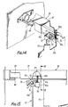
- Figure 14 is a perspective view through part of the apparatus of Figure 13.
- Figure 15 is a transverse cross-sectional view showing the part of the apparatus of Figure 13.
- Figure 16 is a diagram showing the movement of a part of the apparatus of Figure 13.
- Figure 17 is a cross-sectional view through part of the apparatus shown in Figure 15 along line B-B.
- Figure 18 is a cross-sectional view showing another image-forming apparatus of this invention.
- Figure 19 is a cross-sectional view through the part of the apparatus shown in Figure 18 containing the cleaning device.
- Figure 20 is a cross-sectional view through part of the apparatus shown in Figure 19 along line C-C.
- Figure 21 is a diagram showing the movement of part of the apparatus shown in Figure 19.
- An electrophotographic copying machine that is an image formation apparatus of this invention has, as shown in Figure 1, an
optical system 20 in the upper part, and aphotosensitive drum 11 in the center area of the lower part. - The
photosensitive drum 11 can rotate in the direction shown by arrow A, and acharging apparatus 30 containing a corona charger is disposed above thedrum 11. Thecharging apparatus 30 has acorona wire 32 strung along the opening 31a that is provided insideshield box 31. Thecharging apparatus 30 is installed in the copy machine so that thecorona wire 32 is parallel to the central axis of thephotosensitive drum 11. - In the downstream direction of the rotation, of
photosensitive drum 11 of saidcharging apparatus 30, theoptical system 20 provided in the upper part of the copy machine exposes thephotosensitive drum 11. In the downstream direction of the rotation of thephotosensitive drum 11 of the area exposed by theoptical system 20, a developing device 13 is disposed. - Underneath the
photosensitive drum 11, there is a transcription device 41 that uses the corona charger and a separation device 42 in a line. Transcription-paper conveyance route 45 passes in the spaces between thephotosensitive drum 11 and the transcription device 41 and between thephotosensitive drum 11 and the separation device 42. Transcription-paper conveyance route 45 passes toward the fixing means 44 provided toward the side of the machine. In the downstream direction of the rotation ofphotosensitive drum 11 of the separation device 42, there is a cleaning apparatus 14, and further downsteam from that there is a discharging device 43. - The
photosensitive drum 11, the developing device 13, and cleaning apparatus 14 are made into one unit as an image-forming unit 10 (Figure 2), which can be moved along the axis of thephotosensitive drum 11, that is, in the direction in which thecorona wire 32 ofcharger 30 is strung. When the toner inside developing device 13 is consumed, and new toner is to be added into said developing device 13, or when paper has jammed in the transcription-paper conveyance route, or when the cleaning apparatus 14 is repaired, the said image-formingunit 10 can be removed from the machine. The image-formingunit 10 comprises at least one ofphotosensitive drum 11, developing device 13, and cleaning apparatus 14. - A cleaning means 50 is fixed at the end of the image-forming
unit 10 opposite to the direction in which the image-formingunit 10 is pulled out. Particularly, the cleaning means 50 is fixed to theside plate 10a of thephotosensitive drum 11 as shown in Figure 3. The cleaning means 50 is a brush comprising, as shown in Figures 3 and 4, thebody 50a of the brush and aflexible brush portion 50b fixed to thebody 50. As shown in Figure 3 by the lines with paired dots, when the image-formingunit 10 is being removed from the machine, thebrush portion 50b passes through theopening 31a for corona charging of thecharger 30 so as to touch thecorona wire 32. When the image-formingunit 10 is installed in the machine, thebrush portion 50b of the cleaning means 50 is separated from thecorona wire 32 of thecharger 30, as shown by the solid lines in Figure 3, and positioned at the innermost end of thecharger 30 in such a way that thebrush portion 50b is curved by pressure by thewire support 33 that is insulated from thecorona wire 32. Therefore, whencorona wire 32 is charged with voltage and charges thephotosensitive drum 11 with electricity, thebrush portion 50b of the cleaning means 50 is separated from thecorona wire 32, and there is no risk that there will be a leak of electricity from thecorona wire 32 to thephotosensitive drum 11 via the cleaning means 50. - In an electrophotographic copying machine with this kind of construction, the image-forming
unit 10 is positioned within the machine, and copy images are formed by the ordinary electronic copying processing. That is, a high voltage is applied to thecorona wire 32 of thecharger 30 so as to achieve a uniform electric charge of thephotosenstive drum 11, and the electrically chargedphotosensitive drum 11 is exposed to an image of the manuscript by theoptical system 20, so that a latent image is formed. This latent image is developed with toner by the developing apparatus 13. The toner image is transcribed onto transcription paper that is conveyed along the transcription-paper conveyance route 45 by means of transcription device 41. The transcribed transcription paper on which the toner image has been transcribed is separated from thephotosensitive drum 11 by the separator device 42, and then the toner image is fixed onto the transcription paper by the fixing device 44 before being ejected to the outside of the machine. After the toner image has been transcribed, the remaining toner is cleaned from the surface of thephotosensitive drum 11 by the cleaning apparatus 14. - In this way, a copy image of toner on transcription paper is obtained. Each time a copy image is formed, some of the toner inside the developing device 13 is consumed, and when about 3000-5000 pages of transcription paper have had copy images formed thereon, the toner inside the developing device 13 is completely used up, so that it becomes necessary to replenish the toner inside the developing device 13.
- When toner is being supplied to the developing device 13, the image-forming
unit 10 is pulled in the direction of the axis of thephotosensitive drum 11, and thebrush portion 50b on the top of the cleaning means 50 at the end of theunit 10 opposite the direction in which the unit is pulled out touches thecorona wire 32 of thecharger 30, and is moved along the saidcorona wire 32 in a direction parallel to the axis of thephotosensitive drum 11, which causes the removal of silicon compounds, etc., from thecorona wire 32. - Moreover, when the toner has been added to the developing device 13 and the image-forming
unit 10 is being replaced into the inside of the machine, then, the cleaning means 50, likewise, moves along thecorona wire 32 so as to clean the saidcorona wire 32. Then, when the image-formingunit 10 is again installed into the machine, thebrush portion 50b of the cleaning means 50 is bent by thewire support 33 inside of thecorona charger 30 so that they separate from thecorona wire 32. Therefore, there is no risk that thecorona wire 32 will leak electricity from the cleaning means 50 to thephotosensitive drum 11. - In this way, not only when the toner is being supplied to the developing apparatus 13, but also when paper jams in transcription-paper conveyance route 45 or when the cleaning apparatus 14 is repaired, the image-forming
unit 10 is pulled from the machine, and each time theunit 10 is removed, thecorona wire 32 is cleaned by the cleaning means 50. - Figures 5 and 6 show another image-formation apparatus of this invention, in which a cleaning means 50 is disposed within a
box 51 so that it can move up and down inside of thebox 51. The cleaning means 50 is held in the upward position by a pushingspring 52 inside of thebox 51, projecting out of the opening formed in the top surface of thebox 51. In the lower part of thebody 50a of the cleaning means 50, there is aprojection 50c provided so as to prevent the removal of said cleaning means 50 from thebox 51. Theprojection 50c engages with the edge of the opening of thebox 51 and prevents the cleaning means 50 from being removed. - A pair of
guide plates 700 is fixed to the bottom of the wire supports 33 at the far side of thecharger 30 as shown in Figure 6. Theguide plates 700 are positioned with an appropriate space therebetween and the innermost portion of eachguide plate 700 slants in the downward direction. Thebody 50a of the cleaning means 50 is in contact with theguide plates 700 at their upper surfaces. When the cleaning means 50 touches theguide plates 700, thebrush portion 50b of the cleaning means 50 is positioned in the space between theguide plates 700, and when the image-formingunit 10 is inside of the machine, the cleaning means 50 is guided by bothguide plates 700 to move in the downward direction, and the tip ofbrush portion 50b is separated from thecorona wire 32. Then, when image-formingunit 10 is entirely inside of the machine, the tip ofbrush portion 50b of said cleaning means 50 no longer touches the bottom surface of the wire supports 33. - In an image-forming apparatus with this kind of construction, when the image-forming
unit 10 is pulled from the machine, the cleaning means 50 is moved upward by the force of a pushingspring 52, while being guided upward by theguide plates 700. By this movement, thebrush portion 50b is brought to touch thecorona wire 32. Then, as the image-formingunit 10 is pulled away, the saidbrush portion 50b comes into contact with thecorona wire 32, cleaning it. - In the same way as when the image-forming
unit 10 is installed in the machine, thebrush portion 50b of the cleaning means 50 comes into contact with thecorona wire 32 to clean it. When the cleaning means 50 reaches the back interior area of the machine, the cleaning means 50 touches theguide plates 700. Then, when the cleaning means 50 is pushed still farther into the inside, itsbody 50a is pushed downward by theguide plates 700 so as to be pushed into thebox 51. When image-formingunit 10 is installed in the machine, the tip ofbrush portion 50b of the cleaning means 50 does not touch the chargingdevice 30. For this reason, even when the image-formingunit 10 is installed in the machine, thebrush portion 50b of the cleaning means 50 is not bent by force, so its lifespan is considerably improved. - Another image-formation apparatus of this invention is shown in Figures 7-12, in which a rotataable means 6 is attached to the
side plate 10a of thephotosensitive drum 11 so that the rotatable means 6 can rotate at right angles to the corona wire, and it is attached as one piece to the cleaning means 50. - The rotatable means 6 has, as shown in Figures 8 and 9, a
rotatable part 60a, a slidingplate 61, and aguide plate 62. Therotatable part 60a is made in one piece withbody 50a of the cleaning means 50. The saidrotatable part 60a has ahole 600a. The slidingplate 61 can be moved in the direction in which the image-formingunit 10 is pulled (the direction in which thecorona wire 32 is strung within the corona charger 30) via both thehole 100a of theside plate 10a of thedrum 11 and thehole 600a of therotatable part 60a. Theguide plate 62 functions to guide the slidingplate 61, so that it prevents the slidingplate 61 from rotating when the slidingplate 61 slides within thehole 100a of theside plate 10a. Therotatable part 60a mentioned above is fixed so that it can rotate on the edge of thehole 100a of theside plate 10a.Stoppers 60b are disposed on the edge of thehole 600a of therotatable part 60a as one piece, and are engaged with the edge of thehole 100a of theside plate 10a so that therotatable part 60a rotates within thehole 100a of theside plate 10a without separating from theside plate 10a while the slidingplate 61 is sliding. Oneend 62a of theguide plate 62 is fixed withscrew 66 on the end of the slidingplate 61, and theother end 62b is formed in the free end that passeshole 620 of theside plate 10a. The slidingplate 61 has aspring 63, and by its spring force, theend 62a of theguide plate 62 that is fixed to the tip of the slidingplate 61 is always kept touching therotatable part 60a. The slidingplate 61 is made in a twisted shape so that the ends of the slidingplate 61 in the sliding direction are at right angles to each other. For that reason, when the slidingplate 61 slides within thehole 100a of theside plate 10a and within thehole 600a of therotatable part 60a, therotatable part 60a turns in its center along the twisted shape of the slidingplate 61. While the image-formingunit 10 is pulled from its fixed position in the machine or while it is installed in a fixed position, as shown in Figure 10, the slidingplate 61 is pushed out to its fullest extent from the back of theside plate 10a by the force ofspring 63. At this time, therotatable part 60a permits thebrush portion 50b of the cleaning means 50 to touch the corona wire 32 (Figures 10 and 11), so that thecorona wire 32 is cleaned by thebrush portion 50b. When the image-formingunit 10 is installed in its fixed position inside of the machine, then, as shown in Figure 7 and Figure 8, the ends of the slidingplate 61 are pushed against theside plate 16 on the back of theside plate 10a. For that reason, the slidingplate 61 slides within theholes side plate 10a. The result is that, as shown in Figure 12, therotatable part 60a revolves in that center along the twisted shape of the slidingplate 61, making it possible for thebrush portion 50b and thecorona wire 32 to separate. - In the three forms of apparatus mentioned above, when the image-forming
unit 10 is pulled from the machine, the cleaning means 50 does not take up space in the direction of the axis of thedrum 11, which makes the installation and removal of thedrum 11 more easy. - Figures 13-17 show another image-formation apparatus of this invention, in which the cleaning means 50 is attached to a rotatable means 70. The rotatable means 70 can rotate in the plane that includes the
corona wire 32 of thecorona charger 30. The rotatable means 70 has, for example, gears on its outer perimeter, and thebody 50a of thecleaning device 50 is attached to the said rotatable means 70 as one piece. The rotatable means 70 is supported by asupport shaft 71 so as to be able to rotate. The saidsupport shaft 71 is supported inside ofbrackets 72 that are attached to theside plate 10a of the image-formingunit 10. - The
cleaning device 50 is engaged with one end of acoiled spring 74 supported by thesupport shaft 71. The other end of the coiledspring 74 is engaged with thebracket 72, and pushes thecleaning device 50 in the upward direction. Thebracket 72 has astopper 75 that controls the rotation of thecleaning device 50 in the upper direction caused by the force of the coiledspring 74, so that thecleaning device 50 can be at a fixed position on the upper part of the cut-outarea 10b of theside plate 10a. When thecleaning device 50 is moved in the upward direction by the force of the coiledspring 74, it is placed inside of the image-formingunit 10 through the cut-outarea 10b of theside plate 10a. In these circumstances, thecleaning device 50 is controlled in its rotation upward by thestopper 75. At this time, thecleaning device 50 has itsbrush portion 50b become almost perpendicular. The saidbrush portion 50b touches thecorona wire 32 of thecharger 30 with its tip when the image-formingunit 10 is pulled out. - The bottom surface of a
wire supporter 33 that is positioned at the innermost portion of thecharger 30 is provided with aguide rack 80. Therack 80, when the image-formingunit 10 is pushed inside of the machine, can be engaged with the gears of the rotatable means 70, and when the image-formingunit 10 is pushed further inside of the machine, therotatable part 70 revolves because of this engagement. By the revolution of the rotatable means 70, thecleaning device 50, which is made as one piece with the said rotatable means 70, moves downward, in opposition to the force of the coiledspring 74, and itsbrush portion 50b, as shown in Figure 16, is separated from thecorona wire 32 so as to become horizontal. - At the time of supplying of toner to the inside of the developing apparatus 13, the image-forming
unit 10 is pulled in the direction of the axis of thephotosensitive drum 11, and the rotatable means 70, which is engaged with therack 80, moves on therack 80, resulting in a movement of thecleaning device 50 in the upward direction. Then, as the image-formingunit 10 is pulled out, the gears of the rotatable means 70 separate from therack 80, and thecleaning device 50 is revolved in the upward direction yet more by the force of coiledspring 74, and touches thestopper 75. By this, the tip of thebrush portion 50b of thecleaning device 50 passes opening 31a of theshield box 31 of the chargingdevice 30 so as to touch thecorona wire 32. As the image-formingunit 10 is pulled out still more, thebrush portion 50b moves along thecorona wire 32, and by means of this movement, thebrush portion 50b cleans the silicon compounds, etc., that are adhering to thecorona wire 32. - In the case where toner is supplied to the developing device 13 and the image-forming
unit 10 is once more installed in the machine, in the same way, thebrush portion 50b of thecleaning device 50 touches thecorona wire 32, cleaning it. - Then, when the image-forming
unit 10 is pushed back into the machine, the gears of the rotatable means 70 that are attached to the innermost portion of the said image-formingunit 10 are engaged with therack 80 that is provided on the back interior surface of the machine. In this situation, if the image-formingunit 10 is pushed in still more, the rotatable means 70 moves on therack 80, which causes rotation of thecleaning unit 50, which is made in one piece with the rotatable means 70, in the downward direction in opposition to the force of the coiledspring 74, thereby achieving the separation thereof from thecorona wire 32. When the image-formingunit 10 is installed in its fixed position inside of the machine, thebody 50a of thecleaning device 50 is positioned outside of the image-formingunit 10 through the upper part of the cut-outarea 10b of theside plate 10a of the image-formingunit 10, where thebrush portion 50b is almost perpendicular and are positioned within the said cut-outarea 10b. - Figures 18-21 show another image-formation apparatus of this invention, in which to the side of the
shield box 31 of thecharger 30, there is a pair of guide racks 81 that are installed over the whole region of thecharger 30. Eachrack 81 is parallel with thecorona wire 32, and theracks 81 are curved in the downward direction so as to be separated from thecorona wire 32 at the far inside surface of the body of the machine. - The
side plate 10a is provided with a pair of pinion gears 91 that form a rotatable means and thecleaning device 50 that is formed in once piece with the said pinion gears 91. Both pinion gears 91 are engaged with theracks 81 mentioned above. Eachpinion gear 91 is fixed at the supportingshaft 93, which is rotatably supported by a pair of plate springs 94 attached to theside plate 10a of the image-formingunit 10. Eachplate spring 94 extends from theside plate 10a to the back interior side of the machine. The supportingshaft 93 is supported by these extensions of theplate spring 94. Both plate springs 94 push the supportingshaft 93 toward thecharger 30. Therefore, the two pinion gears 91 that are attached to the said supportingshaft 93 are pushed against theracks 81, and move along theracks 81. Eachpinion gear 91 is supported by theside plate 10a so that is moves along the plane including thecorona wire 32, and moves along theracks 81. - The
cleaning device 50 is a rotating brush, which has abody 50a in the shape of a cylinder fixed to almost the central part of the supportingshaft 93 that faces thecorona wire 32 through the chargingopening 31a, andflexible brush portion 50b that extends along the entire circumference of thebody 50a. The tip of thebrush portion 50b touches thecorona wire 32 through the chargingopening 31a of thecharger 30, and moves on thecorona wire 32 by the rotation of the supportingshaft 93. - The
side plate 10a of the image-formingunit 10 has, as shown in Figure 20, a cut-outarea 10b in the region where the pinion gears 91 rotate with thecleaning device 50. The outside surface of theside plate 10a has a cleaning means 95 near the cut-outarea 10b, which is placed so that the tip of thebrush portion 50b touches the cleaning means 95. For the cleaning means 95, for example, felt can be used. The tips of thebrush portion 50b touch the cleaning means 95 during the rotation by thebrush portion 50b of thecleaning device 50, which causes the cleaning of matter that has adhered to the saidbrush portion 50b. - When toner is replenished in the developing apparatus 13, the image-forming
unit 10 is pulled out in the direction of the axis of thephotosensitive drum 11, and the pinion gears 91 attached to the end of the image-formingunit 10 opposite to the direction of the pulling out rotate while touching theracks 81. When eachpinion gear 91 reaches the innermost portion of therack 81, it is pushed by theplate spring 94 so that it moves in the direction toward thecharger 30. By this, thecleaning device 50, to which is attached the supportingshaft 93 that supports the pinion gears 91, also approaches thecharger 30, and thebrush portion 50b touches thecorona wire 32 through the chargingopening 31a. When the image-formingunit 10 is pulled farther from the machine, the pinion gears 91 rotate while touching theracks 81, which causes the rotation of thesupport shaft 93, resulting in the rotation of thecleaning device 50. Because of the rotation of cleaningdevice 50, thebrush portion 50b touches thecorona wire 32, and cleans silicon compounds, etc., that have adhered to the saidcorona wire 32. - The matter that has adhered to the corona wire adhere to the tip of the
brush portion 50b of thecleaning device 50. However, when thecleaning device 50 rotates and thebrush portion 50b passes through the cut-outarea 10b of theside plate 10a of the image-formingunit 10, the tip thereof touches the cleaning means 95, and the matter that has adhered to the saidbrush portion 50b is cleaned therefrom. - When toner is supplied to the developing device 13 and the image-forming
unit 10 is installed into the machine, in the same way, thecleaning device 50 touches thecorona wire 32 and cleans it. Then, when theside plate 10a of the image-formingunit 10 reaches the inner back side of the machine, the pinion gears 91 are guided by thecurved racks 81 so as to be separated from the chargingdevice 30, and rotate downward so as to be separated from the chargingdevice 30; together with this movement, thecleaning device 50 is separated from thecorona wire 32. When the image-formingunit 10 is installed in its fixed position inside of the machine, thecleaning device 50 is completely separated from thecorona wire 32, and is in a place far from the charging region of thecorona wire 32.
Claims (19)
Applications Claiming Priority (4)
| Application Number | Priority Date | Filing Date | Title |
|---|---|---|---|
| JP245117/86 | 1986-10-15 | ||
| JP24511786 | 1986-10-15 | ||
| JP61313889A JPH0760282B2 (en) | 1986-10-15 | 1986-12-26 | Image forming device |
| JP313889/86 | 1986-12-26 |
Publications (3)
| Publication Number | Publication Date |
|---|---|
| EP0267689A2 true EP0267689A2 (en) | 1988-05-18 |
| EP0267689A3 EP0267689A3 (en) | 1988-11-02 |
| EP0267689B1 EP0267689B1 (en) | 1990-12-12 |
Family
ID=26537049
Family Applications (1)
| Application Number | Title | Priority Date | Filing Date |
|---|---|---|---|
| EP87309071A Expired - Lifetime EP0267689B1 (en) | 1986-10-15 | 1987-10-14 | An apparatus for the formation of images |
Country Status (5)
| Country | Link |
|---|---|
| US (1) | US4811050A (en) |
| EP (1) | EP0267689B1 (en) |
| JP (1) | JPH0760282B2 (en) |
| KR (1) | KR910003928B1 (en) |
| DE (1) | DE3766691D1 (en) |
Cited By (4)
| Publication number | Priority date | Publication date | Assignee | Title |
|---|---|---|---|---|
| US8013099B2 (en) | 2005-09-22 | 2011-09-06 | Basf Coatings Ag | Use of phosphonic acid diesters and diphosphonic acid diesters and silane group containing, curable mixtures containing phosphonic acid diesters and diphosphonic acid diesters |
| US8138249B2 (en) | 2007-03-23 | 2012-03-20 | Basf Coatings Japan Ltd. | Phosphonate-containing two-component coating system and the production and use thereof |
| US9018330B2 (en) | 2006-05-29 | 2015-04-28 | Basf Coatings Gmbh | Use of curable mixtures comprising silane group-containing compounds and phosphonic acid diester or diphosphonic acid diester as adhesives |
| US10294389B2 (en) | 2005-09-22 | 2019-05-21 | Basf Coatings Gmbh | Use of phosphonic acid diesters and diphosphonic acid diesters and thermally curable mixtures containing phosphonic acid diesters and diphosphonic acid diesters |
Families Citing this family (10)
| Publication number | Priority date | Publication date | Assignee | Title |
|---|---|---|---|---|
| JPH04194971A (en) * | 1990-11-27 | 1992-07-14 | Minolta Camera Co Ltd | Image forming device |
| JP2769251B2 (en) * | 1991-05-24 | 1998-06-25 | キヤノン株式会社 | Image forming device |
| KR950011874B1 (en) * | 1992-12-10 | 1995-10-11 | 현대전자산업주식회사 | Method and apparatus for automatically cleaning charging wires |
| US5485255A (en) * | 1994-08-31 | 1996-01-16 | Eastman Kodak Company | Automatic cleaning mechanism for a corona charger using cleaning pad |
| KR0134699B1 (en) * | 1994-12-27 | 1998-04-30 | 김광호 | Charger cleaner in apparatus for electro-graphic device |
| DE10085491T1 (en) * | 2000-11-08 | 2003-10-16 | Fujitsu Ltd | Imaging device |
| US7493060B2 (en) * | 2005-09-16 | 2009-02-17 | Xerox Corporation | Cleaning system for removing dendrites from a charging device in a xerographic printer |
| EP2109506A2 (en) * | 2007-01-24 | 2009-10-21 | Ventiva, Inc. | Method and device to prevent dust agglomeration on corona electrodes |
| JP5451093B2 (en) * | 2009-01-30 | 2014-03-26 | キヤノン株式会社 | Sheet conveying apparatus and image forming apparatus |
| US8676087B2 (en) * | 2010-06-30 | 2014-03-18 | Brother Kogyo Kabushiki Kaisha | Image forming device having charging wire cleaning mechanism |
Citations (6)
| Publication number | Priority date | Publication date | Assignee | Title |
|---|---|---|---|---|
| US3891846A (en) * | 1972-01-18 | 1975-06-24 | Canon Kk | Corona discharger cleaning apparatus |
| US3965400A (en) * | 1975-02-24 | 1976-06-22 | Xerox Corporation | Corona generating device with improved built-in cleaning mechanism |
| JPS58173757A (en) * | 1982-04-07 | 1983-10-12 | Canon Inc | Cleaning mechanism of charging device of electrostatic copying machine |
| JPS58186761A (en) * | 1982-04-26 | 1983-10-31 | Fuji Xerox Co Ltd | Corotron device |
| JPS59111656A (en) * | 1982-12-17 | 1984-06-27 | Fuji Xerox Co Ltd | Corotron wire cleaning device of copying machine |
| JPS61117579A (en) * | 1984-11-14 | 1986-06-04 | Fuji Xerox Co Ltd | Cleaning device of corona discharger |
Family Cites Families (8)
| Publication number | Priority date | Publication date | Assignee | Title |
|---|---|---|---|---|
| JPS54146635A (en) * | 1978-05-09 | 1979-11-16 | Canon Inc | Corona discharge instrument |
| US4470689A (en) * | 1981-06-02 | 1984-09-11 | Canon Kabushiki Kaisha | Image forming apparatus and process unit |
| US4566777A (en) * | 1982-08-23 | 1986-01-28 | Canon Kabushiki Kaisha | Process kit for image forming apparatus |
| JPS6068557U (en) * | 1983-10-17 | 1985-05-15 | キヤノン株式会社 | Discharger cleaning device |
| JPS60249169A (en) * | 1984-05-24 | 1985-12-09 | Canon Inc | Cleaning device for corona discharger |
| US4734580A (en) * | 1986-06-16 | 1988-03-29 | The Simco Company, Inc. | Built-in ionizing electrode cleaning apparatus |
| JPH0668557A (en) * | 1992-08-21 | 1994-03-11 | Matsushita Electric Ind Co Ltd | Tape carrying device |
| JPH06139080A (en) * | 1992-10-27 | 1994-05-20 | Shikoku Nippon Denki Software Kk | Event circulation processing system |
-
1986
- 1986-12-26 JP JP61313889A patent/JPH0760282B2/en not_active Expired - Lifetime
-
1987
- 1987-10-14 US US07/108,592 patent/US4811050A/en not_active Expired - Lifetime
- 1987-10-14 DE DE8787309071T patent/DE3766691D1/en not_active Expired - Lifetime
- 1987-10-14 EP EP87309071A patent/EP0267689B1/en not_active Expired - Lifetime
- 1987-10-15 KR KR1019870011586A patent/KR910003928B1/en not_active IP Right Cessation
Patent Citations (6)
| Publication number | Priority date | Publication date | Assignee | Title |
|---|---|---|---|---|
| US3891846A (en) * | 1972-01-18 | 1975-06-24 | Canon Kk | Corona discharger cleaning apparatus |
| US3965400A (en) * | 1975-02-24 | 1976-06-22 | Xerox Corporation | Corona generating device with improved built-in cleaning mechanism |
| JPS58173757A (en) * | 1982-04-07 | 1983-10-12 | Canon Inc | Cleaning mechanism of charging device of electrostatic copying machine |
| JPS58186761A (en) * | 1982-04-26 | 1983-10-31 | Fuji Xerox Co Ltd | Corotron device |
| JPS59111656A (en) * | 1982-12-17 | 1984-06-27 | Fuji Xerox Co Ltd | Corotron wire cleaning device of copying machine |
| JPS61117579A (en) * | 1984-11-14 | 1986-06-04 | Fuji Xerox Co Ltd | Cleaning device of corona discharger |
Non-Patent Citations (4)
| Title |
|---|
| PATENT ABSTRACTS OF JAPAN, vol. 10, no. 300 (P-506)[2356], 14th October 1986; & JP-A-61 117 579 (FUJI XEROX CO., LTD) 04-06-1986 * |
| PATENT ABSTRACTS OF JAPAN, vol. 8, no. 14 (P-249)[1451], 21st January 1984; & JP-A-58 173 757 (CANON K.K.) 12-10-1983 * |
| PATENT ABSTRACTS OF JAPAN, vol. 8, no. 237 (P-310)[1674], 30th October 1984; & JP-A-59 111 656 (FUJI XEROX K.K.) 27-06-1984 * |
| PATENT ABSTRACTS OF JAPAN, vol. 8, no. 31 (P-253)[1468], 9th February 1984; & JP-A-58 186 761 (FUJI XEROX K.K.) 31-10-1983 * |
Cited By (4)
| Publication number | Priority date | Publication date | Assignee | Title |
|---|---|---|---|---|
| US8013099B2 (en) | 2005-09-22 | 2011-09-06 | Basf Coatings Ag | Use of phosphonic acid diesters and diphosphonic acid diesters and silane group containing, curable mixtures containing phosphonic acid diesters and diphosphonic acid diesters |
| US10294389B2 (en) | 2005-09-22 | 2019-05-21 | Basf Coatings Gmbh | Use of phosphonic acid diesters and diphosphonic acid diesters and thermally curable mixtures containing phosphonic acid diesters and diphosphonic acid diesters |
| US9018330B2 (en) | 2006-05-29 | 2015-04-28 | Basf Coatings Gmbh | Use of curable mixtures comprising silane group-containing compounds and phosphonic acid diester or diphosphonic acid diester as adhesives |
| US8138249B2 (en) | 2007-03-23 | 2012-03-20 | Basf Coatings Japan Ltd. | Phosphonate-containing two-component coating system and the production and use thereof |
Also Published As
| Publication number | Publication date |
|---|---|
| US4811050A (en) | 1989-03-07 |
| DE3766691D1 (en) | 1991-01-24 |
| JPS63226673A (en) | 1988-09-21 |
| EP0267689A3 (en) | 1988-11-02 |
| KR910003928B1 (en) | 1991-06-17 |
| JPH0760282B2 (en) | 1995-06-28 |
| EP0267689B1 (en) | 1990-12-12 |
| KR880005493A (en) | 1988-06-29 |
Similar Documents
| Publication | Publication Date | Title |
|---|---|---|
| EP0267689B1 (en) | An apparatus for the formation of images | |
| US5095335A (en) | Copier with retractable charging unit to prevent damage to drum when removing process cartridge | |
| EP0166871B1 (en) | Electrostatic copying apparatus | |
| US5471284A (en) | Image forming apparatus having toner depletion detection feature | |
| EP0453058A2 (en) | Apparatus for forming an image on a record medium | |
| JPS5840578A (en) | Attaching and detaching device for cleaning device | |
| JP3577689B2 (en) | Image forming device | |
| USRE33844E (en) | Transfer medium separation in a recording apparatus | |
| US5345295A (en) | Positioning member for a separation electrode mounted on a clamshell-type copier | |
| US5537189A (en) | Printing apparatus which grounds photoreceptor independently of CRU | |
| JP2576538Y2 (en) | Mounting mechanism for process cartridges for electrophotographic devices | |
| US5608499A (en) | Apparatus and method for cleaning rollers in image formers | |
| US5227841A (en) | Image forming apparatus having unit support member thereon | |
| JPH11338265A (en) | Transfer electrifier | |
| JPS5825650A (en) | Image forming device | |
| JPH0511565Y2 (en) | ||
| JPH01117151A (en) | Image former | |
| US5172174A (en) | Transfer device with insulated shield | |
| JPS5984260A (en) | Picture forming device | |
| JPH0548920B2 (en) | ||
| JP3416834B2 (en) | Image forming device | |
| KR100275085B1 (en) | Image forming apparatus with a device to increase contact area between transfer sheet and image carrier | |
| JPS60111259A (en) | Image forming device | |
| JP3740181B2 (en) | Charger cleaning tool | |
| KR0115430Y1 (en) | Useless toner transfer and supplying device of electronic copier |
Legal Events
| Date | Code | Title | Description |
|---|---|---|---|
| PUAI | Public reference made under article 153(3) epc to a published international application that has entered the european phase |
Free format text: ORIGINAL CODE: 0009012 |
|
| AK | Designated contracting states |
Kind code of ref document: A2 Designated state(s): DE FR GB NL |
|
| PUAL | Search report despatched |
Free format text: ORIGINAL CODE: 0009013 |
|
| AK | Designated contracting states |
Kind code of ref document: A3 Designated state(s): DE FR GB NL |
|
| 17P | Request for examination filed |
Effective date: 19881221 |
|
| 17Q | First examination report despatched |
Effective date: 19890505 |
|
| GRAA | (expected) grant |
Free format text: ORIGINAL CODE: 0009210 |
|
| AK | Designated contracting states |
Kind code of ref document: B1 Designated state(s): DE FR GB NL |
|
| ET | Fr: translation filed | ||
| REF | Corresponds to: |
Ref document number: 3766691 Country of ref document: DE Date of ref document: 19910124 |
|
| PLBE | No opposition filed within time limit |
Free format text: ORIGINAL CODE: 0009261 |
|
| STAA | Information on the status of an ep patent application or granted ep patent |
Free format text: STATUS: NO OPPOSITION FILED WITHIN TIME LIMIT |
|
| 26N | No opposition filed | ||
| PGFP | Annual fee paid to national office [announced via postgrant information from national office to epo] |
Ref country code: GB Payment date: 19971006 Year of fee payment: 11 |
|
| PGFP | Annual fee paid to national office [announced via postgrant information from national office to epo] |
Ref country code: FR Payment date: 19971009 Year of fee payment: 11 |
|
| PGFP | Annual fee paid to national office [announced via postgrant information from national office to epo] |
Ref country code: DE Payment date: 19971017 Year of fee payment: 11 |
|
| PGFP | Annual fee paid to national office [announced via postgrant information from national office to epo] |
Ref country code: NL Payment date: 19971029 Year of fee payment: 11 |
|
| PG25 | Lapsed in a contracting state [announced via postgrant information from national office to epo] |
Ref country code: GB Free format text: LAPSE BECAUSE OF NON-PAYMENT OF DUE FEES Effective date: 19981014 |
|
| PG25 | Lapsed in a contracting state [announced via postgrant information from national office to epo] |
Ref country code: NL Free format text: LAPSE BECAUSE OF NON-PAYMENT OF DUE FEES Effective date: 19990501 |
|
| GBPC | Gb: european patent ceased through non-payment of renewal fee |
Effective date: 19981014 |
|
| PG25 | Lapsed in a contracting state [announced via postgrant information from national office to epo] |
Ref country code: FR Free format text: LAPSE BECAUSE OF NON-PAYMENT OF DUE FEES Effective date: 19990630 |
|
| NLV4 | Nl: lapsed or anulled due to non-payment of the annual fee |
Effective date: 19990501 |
|
| REG | Reference to a national code |
Ref country code: FR Ref legal event code: ST |
|
| PG25 | Lapsed in a contracting state [announced via postgrant information from national office to epo] |
Ref country code: DE Free format text: LAPSE BECAUSE OF NON-PAYMENT OF DUE FEES Effective date: 19990901 |