EP0267232B1 - Compact battery-powered printer - Google Patents
Compact battery-powered printer Download PDFInfo
- Publication number
- EP0267232B1 EP0267232B1 EP87903067A EP87903067A EP0267232B1 EP 0267232 B1 EP0267232 B1 EP 0267232B1 EP 87903067 A EP87903067 A EP 87903067A EP 87903067 A EP87903067 A EP 87903067A EP 0267232 B1 EP0267232 B1 EP 0267232B1
- Authority
- EP
- European Patent Office
- Prior art keywords
- printer apparatus
- battery
- roller
- portable printer
- batteries
- Prior art date
- Legal status (The legal status is an assumption and is not a legal conclusion. Google has not performed a legal analysis and makes no representation as to the accuracy of the status listed.)
- Expired - Lifetime
Links
- 238000010276 construction Methods 0.000 claims abstract description 8
- 238000007639 printing Methods 0.000 claims description 14
- 230000008878 coupling Effects 0.000 claims description 5
- 238000010168 coupling process Methods 0.000 claims description 5
- 238000005859 coupling reaction Methods 0.000 claims description 5
- 238000005549 size reduction Methods 0.000 abstract 1
- 238000003780 insertion Methods 0.000 description 4
- 230000037431 insertion Effects 0.000 description 4
- 230000000694 effects Effects 0.000 description 3
- 238000005516 engineering process Methods 0.000 description 3
- 230000001680 brushing effect Effects 0.000 description 2
- 230000008901 benefit Effects 0.000 description 1
- OJIJEKBXJYRIBZ-UHFFFAOYSA-N cadmium nickel Chemical compound [Ni].[Cd] OJIJEKBXJYRIBZ-UHFFFAOYSA-N 0.000 description 1
- 230000000295 complement effect Effects 0.000 description 1
- 230000007423 decrease Effects 0.000 description 1
- 238000001514 detection method Methods 0.000 description 1
- 239000002783 friction material Substances 0.000 description 1
- 238000010438 heat treatment Methods 0.000 description 1
- 230000003116 impacting effect Effects 0.000 description 1
- 238000007641 inkjet printing Methods 0.000 description 1
- 238000009434 installation Methods 0.000 description 1
- 239000011159 matrix material Substances 0.000 description 1
- 230000004048 modification Effects 0.000 description 1
- 238000012986 modification Methods 0.000 description 1
- 230000009467 reduction Effects 0.000 description 1
- 230000000717 retained effect Effects 0.000 description 1
Images




Classifications
-
- B—PERFORMING OPERATIONS; TRANSPORTING
- B41—PRINTING; LINING MACHINES; TYPEWRITERS; STAMPS
- B41J—TYPEWRITERS; SELECTIVE PRINTING MECHANISMS, i.e. MECHANISMS PRINTING OTHERWISE THAN FROM A FORME; CORRECTION OF TYPOGRAPHICAL ERRORS
- B41J3/00—Typewriters or selective printing or marking mechanisms characterised by the purpose for which they are constructed
- B41J3/36—Typewriters or selective printing or marking mechanisms characterised by the purpose for which they are constructed for portability, i.e. hand-held printers or laptop printers
-
- H—ELECTRICITY
- H01—ELECTRIC ELEMENTS
- H01M—PROCESSES OR MEANS, e.g. BATTERIES, FOR THE DIRECT CONVERSION OF CHEMICAL ENERGY INTO ELECTRICAL ENERGY
- H01M50/00—Constructional details or processes of manufacture of the non-active parts of electrochemical cells other than fuel cells, e.g. hybrid cells
- H01M50/20—Mountings; Secondary casings or frames; Racks, modules or packs; Suspension devices; Shock absorbers; Transport or carrying devices; Holders
- H01M50/204—Racks, modules or packs for multiple batteries or multiple cells
- H01M50/207—Racks, modules or packs for multiple batteries or multiple cells characterised by their shape
- H01M50/213—Racks, modules or packs for multiple batteries or multiple cells characterised by their shape adapted for cells having curved cross-section, e.g. round or elliptic
-
- Y—GENERAL TAGGING OF NEW TECHNOLOGICAL DEVELOPMENTS; GENERAL TAGGING OF CROSS-SECTIONAL TECHNOLOGIES SPANNING OVER SEVERAL SECTIONS OF THE IPC; TECHNICAL SUBJECTS COVERED BY FORMER USPC CROSS-REFERENCE ART COLLECTIONS [XRACs] AND DIGESTS
- Y02—TECHNOLOGIES OR APPLICATIONS FOR MITIGATION OR ADAPTATION AGAINST CLIMATE CHANGE
- Y02E—REDUCTION OF GREENHOUSE GAS [GHG] EMISSIONS, RELATED TO ENERGY GENERATION, TRANSMISSION OR DISTRIBUTION
- Y02E60/00—Enabling technologies; Technologies with a potential or indirect contribution to GHG emissions mitigation
- Y02E60/10—Energy storage using batteries
Definitions
- the present invention relates to battery- powered printing apparatus, and more particularly to a space-economizing construction for such apparatus.
- output printers use various printing technologies, e.g. impression or dot matrix impacting, thermal dye transferring and ink jet printing such as piezo-electric or thermal drop on demand devices.
- a common requirement for output printers using the above or other printing technologies is an electrical power source.
- an important purpose of the present invention is to provide improved configurations which contribute significantly toward enhanced compactness in a battery-operable printer.
- the invention is advantageous from the viewpoint of providing the user a more readily portable output printer, e.g. easily fitting within a portion of a briefcase.
- the invention also is advantageous in providing adequate power for such a printer in reliably operable construction.
- the present invention provides a conveniently located battery housing and an easily effected mode of battery installation.
- a printer of the kind having electrically powered printing components and a print medium transport means, such as a feeding and/or guiding member an improved power supply construction that comprises a battery housing formed within such transport means, terminals couplable to batteries inserted in such housing and circuit means connecting those terminals to electrically operated components of the output printer.
- the exemplary printer embodiment shown in Figure 1 comprises a main housing 10 within which are mounted print head motor 11, platen motor 12, and printing and drive control circuit boards 13.
- the motor 11 is coupled via a gear reduction drive (shown generally as 14) to a cable drive spindle 15 housed in journal 16. Rotation of motor 11 traverses print head assembly 17 along its support bar 18 by virtue of its coupling to one strand of endless drive cable 19.
- Motor 12 is coupled to the print media transport system 20 by gear means, e.g. a gear train or geared drive belt 29.
- the transport system 20 is described in greater detail below, however, in general it functions to move print medium, e.g. paper, past the transversing printing path of the print head 17.
- print sheet portions are sequentially indexed and the print head traverses across the indexed portion to effect printing, e.g. by ejected ink drops, selective thermal heating or by impact printing.
- the ink jet print head 17 (with ejection orifices 17a) is only exemplary of various printing technologies with which the present invention is useful.
- the printer of this embodiment of the invention comprises a rotatable platen 21 having thereon sprocket teeth 22 which are constructed for advancing tractor-fed paper types.
- the ends 23 of the platen are coupled to end plates 24, one of which has a drive gear 25 adapted to mesh with gear means 29.
- Both end plates 24 have bearing surfaces 26 adapted to support the platen for rotation on the journal surface 27a of shaft 27.
- a bail assembly 28 is mounted within the printer to engage friction surfaces 36 of the platen in a known manner.
- the transport system 20 is constructed to house a source of battery power for operating the printer.
- platen 21 is formed as a hollow shell adapted to move around a plurality of cylindrical batteries 31, e.g. five nickel-cadmium "C" size batteries, connected in series.
- the platen 21 comprises an access door 32, which is openable for insertion of the individual batteries and is hinged internally of the platen so as to present a smooth cylindrical surface when closed. After insertion through door 32 the front and rear batteries of the series are moved into supporting engagement with complementary shaped end caps 33, here formed as integral portions of journal shafts 27.
- both end caps contain contact springs 34 which are adapted to make electrical connection with the terminals of inserted batteries and which are coupled to the power distribution system 35 for the printer. From system 35 electrical energy is supplied via portions of control panels 13 to motors 11 and 12, print head 17 and other electrically energized portions of the printer, e.g. execution panel 8, detection and interface electronics of the printer.
- the batteries 31 do not rotate with the platen 21. This is advantageous from the viewpoints of minimizing drive energy and eliminating the necessity of brush contacts. Also, the approach of stationary batteries decreases the momentum of the platen, which is particularly useful in achieving accurate indexing of the platen, and thus the print medium. Thus, rotation of the platen will advance edge-perforated paper print medium via sprockets 22 or individual sheets via the pinching engagement between the roller of bail 28 and the opposing platen surface, which can have a rubber surfacing shown at 36 in Figure 1.
- Figure 3 discloses an advantageous modification of the previously described embodiment wherein the support caps 33 are joined by an arcuate support shelf 37 that extends between the lower sectors of the caps within the bottom of the platen 21.
- all batteries nest in the shelf 37 to prevent rubbing between inserted batteries and the rotating platen 21.
- Figure 4 illustrates another embodiment of the present invention wherein non-rubbing support of the batteries is effected by cooperation of end caps 33 and a battery package which retains the series connected batteries in a "stick" format 31 a by encapsulating wall member 39.
- Such multi- battery packages are commercially available, e.g. the "Power Stick” battery from General Electric Company.
- coil spring 34a forms the electrical contact at one end of the battery stick to facilitate battery insertion into end caps 33.
- the battery access door 32 of the platen 21 is elongated from the size shown in Figure 1 so that the battery stick can be compressed against spring 34a and then released to engage the terminal 34 in the opposite end cap 33.
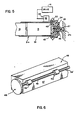
- FIG. 5 shows another preferred embodiment wherein the batteries remain stationary during print media advance.
- the battery stick 31 a described with respect to Figure 4, itself forms a platen over which print media is advanced. Tractor-fed paper advance is again effected by the rotation of sprocket 22; however, ordinary sheet feed is effected by means of a drive 41 coupled to the roller 42 of the bail system 28.
- the battery stick 31a is retained in a stationary operative relation with contacts 34 by magnetic couplings 43.
- FIG. 6 illustrates another embodiment of the invention in which the bail assembly 28' is rotated to effect print medium advance.
- the battery housing 46 forms guide means having a guide surface 47 that directs the print medium into and out of the printing zone.
- the rollers 42 are driven via shaft 48 by drive gear 49, which can be coupled to the gear means 29 of the printer.
- the guide surface 47 is preferably coated with a low friction material.
- the member 46 can be a battery casing itself and, as shown, the battery configuration need not be cylindrical.
- FIGS 7 and 8 illustrate embodiments of the present invention wherein batteries rotate with the media transport system.
- the platen 51 is configured to support the batteries for rotation therewith, i.e., the separate support structure of Figures 2 and 3 has been eliminated.
- end caps 53 are constructed to support spring contacts 54 in brushing connection with the terminals of batteries 31 during rotation of the platen 51.
- a battery stick 31a itself forms the rotative platen of the printer.
- end plates 64 have flanges 64a which are adapted to support the battery stick and to communicate rotative drive thereto.
- the stationary end caps 63 are again constructed to support spring contacts 68 in brushing electrical connection with the end terminals of the battery stick 31 a.
- FIGS 9 and 10 show another embodiment of the invention wherein a plurality of individual batteries or a battery stick can be inserted into a rotatable platen from the side of the printer housing 70.
- a cap 71 is adapted to interfit with an opening 72 of the housing 70, for example by screw threads 73. Electrical connection of inserted batteries to power distribution system 35 is made by means of battery spring 74, which is coupled to contact ring 75 on cap 71.
- ring 75 electrically connects to contact washer 76, which in turn is coupled to system 35.
- Platen-housing 78 is mounted at one end in bearing 79 and coupled at its other end to rotary drive, not shown.
- FIGs 11 and 12 disclose another embodiment of the present invention wherein a battery- stick platen 81 is removable from the printer, e.g. by means of a bottom access door 82.
- tractor feed wheel 83 has a resilient seating recess 84 adapted to be secured on the end of battery stick 81.
- a coupling key portion 85 of feed wheel is adapted to interfit with drive gear 87, and the other end 86 of portion 85 is forced into electrical contact with the terminal of battery stick 81.
- the opposite end of battery stick 81 is similarly fitted with a tractor wheel 83', which has a bearing shaft adapted to seat in a bearing recess of the printer wall.
- the present invention provides significant technical advantage from the viewpoints of providing a more compact battery operable printer, wherein the batteries are also conveniently and reliably housed.
Landscapes
- Chemical & Material Sciences (AREA)
- Chemical Kinetics & Catalysis (AREA)
- Electrochemistry (AREA)
- General Chemical & Material Sciences (AREA)
- Handling Of Sheets (AREA)
- Printers Characterized By Their Purpose (AREA)
- Accessory Devices And Overall Control Thereof (AREA)
Abstract
Description
- The present invention relates to battery- powered printing apparatus, and more particularly to a space-economizing construction for such apparatus.
- As devices such as personal computers and word processors have become more numerous and smaller, there has arisen a concurrent desire to provide smaller output printers for those devices. Such output printers use various printing technologies, e.g. impression or dot matrix impacting, thermal dye transferring and ink jet printing such as piezo-electric or thermal drop on demand devices. A common requirement for output printers using the above or other printing technologies is an electrical power source.
- U.S. Patent 3,344,899 points out that it is highly advantageous for such data transferring machines to be "portable", implying that the machines desirably incorporate their own source of electrical power. However, even with the improvements that have been incorporated into small batteries, the power requirements for operating such output printers necessitates either: (i) the dedication of considerable volume within a printer housing or (ii) the approach of using a separate portable power supply. Neither of these alternatives is attractive from the viewpoint of the consumer who wishes maximum capability with the minimum baggage.
- Thus an important purpose of the present invention is to provide improved configurations which contribute significantly toward enhanced compactness in a battery-operable printer. The invention is advantageous from the viewpoint of providing the user a more readily portable output printer, e.g. easily fitting within a portion of a briefcase. The invention also is advantageous in providing adequate power for such a printer in reliably operable construction. Further, the present invention provides a conveniently located battery housing and an easily effected mode of battery installation.
- The above and other objects are accomplished, in accord with the present invention by providing in a printer of the kind having electrically powered printing components and a print medium transport means, such as a feeding and/or guiding member, an improved power supply construction that comprises a battery housing formed within such transport means, terminals couplable to batteries inserted in such housing and circuit means connecting those terminals to electrically operated components of the output printer.
- The subsequent description of preferred embodiments is set forth with reference to the attached drawings wherein:
- Figure 1 is a perspective view of printer apparatus incorporating one preferred embodiment of the present invention;
- Figure 2 is a cross-sectional view of a portion of the apparatus shown in Figure 1;
- Figure 3 is a cross-sectional view similar to Figure 2, but showing an alternative embodiment of the present invention;
- Figure 4 is a cross-sectional view similar to Figure 2, but showing an alternative embodiment of the present invention;
- Figure 5 is a cross-sectional view similar to Figure 2, but showing an alternative embodiment of the present invention;
- Figure 6 is a partial perspective view showing an alternative embodiment of the present invention;
- Figure 7 is a cross-sectional view similar to Figure 2, but showing an alternative embodiment of the present invention;
- Figure 9 is a partial perspective view showing another embodiment of the present invention;
- Figure 10 is a cross-sectional view of a portion of the Figure 9 embodiment;
- Figure 11 is a perspective view of another embodiment of the invention; and
- Figure 12 is a cross-sectional view of a portion of the Figure 11 embodiment.
- In general, the exemplary printer embodiment shown in Figure 1 comprises a
main housing 10 within which are mounted print head motor 11,platen motor 12, and printing and drivecontrol circuit boards 13. The motor 11 is coupled via a gear reduction drive (shown generally as 14) to a cable drive spindle 15 housed injournal 16. Rotation of motor 11 traverses print head assembly 17 along its support bar 18 by virtue of its coupling to one strand of endless drive cable 19.Motor 12 is coupled to the printmedia transport system 20 by gear means, e.g. a gear train or geareddrive belt 29. Thetransport system 20 is described in greater detail below, however, in general it functions to move print medium, e.g. paper, past the transversing printing path of the print head 17. Thus, under control ofcircuits 13, print sheet portions are sequentially indexed and the print head traverses across the indexed portion to effect printing, e.g. by ejected ink drops, selective thermal heating or by impact printing. That is, the ink jet print head 17 (with ejection orifices 17a) is only exemplary of various printing technologies with which the present invention is useful. - Referring now to Figure 2, as well as Figure 1, it can be seen that the printer of this embodiment of the invention comprises a
rotatable platen 21 having thereonsprocket teeth 22 which are constructed for advancing tractor-fed paper types. Theends 23 of the platen are coupled toend plates 24, one of which has adrive gear 25 adapted to mesh with gear means 29. Bothend plates 24 havebearing surfaces 26 adapted to support the platen for rotation on the journal surface 27a ofshaft 27. Abail assembly 28 is mounted within the printer to engagefriction surfaces 36 of the platen in a known manner. - In the embodiment of the present invention shown in Figures 1 and 2, the
transport system 20 is constructed to house a source of battery power for operating the printer. Specifically,platen 21 is formed as a hollow shell adapted to move around a plurality ofcylindrical batteries 31, e.g. five nickel-cadmium "C" size batteries, connected in series. As shown in Figure 1, theplaten 21 comprises anaccess door 32, which is openable for insertion of the individual batteries and is hinged internally of the platen so as to present a smooth cylindrical surface when closed. After insertion throughdoor 32 the front and rear batteries of the series are moved into supporting engagement with complementary shapedend caps 33, here formed as integral portions ofjournal shafts 27. As shown in Figure 2, both end caps containcontact springs 34 which are adapted to make electrical connection with the terminals of inserted batteries and which are coupled to thepower distribution system 35 for the printer. Fromsystem 35 electrical energy is supplied via portions ofcontrol panels 13 tomotors 11 and 12, print head 17 and other electrically energized portions of the printer, e.g. execution panel 8, detection and interface electronics of the printer. - In operation of the printer shown in Figures 1 and 2, the
batteries 31 do not rotate with theplaten 21. This is advantageous from the viewpoints of minimizing drive energy and eliminating the necessity of brush contacts. Also, the approach of stationary batteries decreases the momentum of the platen, which is particularly useful in achieving accurate indexing of the platen, and thus the print medium. Thus, rotation of the platen will advance edge-perforated paper print medium viasprockets 22 or individual sheets via the pinching engagement between the roller ofbail 28 and the opposing platen surface, which can have a rubber surfacing shown at 36 in Figure 1. - Figure 3 discloses an advantageous modification of the previously described embodiment wherein the
support caps 33 are joined by anarcuate support shelf 37 that extends between the lower sectors of the caps within the bottom of theplaten 21. In this embodiment, all batteries nest in theshelf 37 to prevent rubbing between inserted batteries and the rotatingplaten 21. - Figure 4 illustrates another embodiment of the present invention wherein non-rubbing support of the batteries is effected by cooperation of
end caps 33 and a battery package which retains the series connected batteries in a "stick" format 31 a by encapsulatingwall member 39. Such multi- battery packages are commercially available, e.g. the "Power Stick" battery from General Electric Company. In this embodiment coil spring 34a forms the electrical contact at one end of the battery stick to facilitate battery insertion intoend caps 33. Also, thebattery access door 32 of theplaten 21 is elongated from the size shown in Figure 1 so that the battery stick can be compressed against spring 34a and then released to engage theterminal 34 in theopposite end cap 33. - Figure 5 shows another preferred embodiment wherein the batteries remain stationary during print media advance. In this construction the battery stick 31 a, described with respect to Figure 4, itself forms a platen over which print media is advanced. Tractor-fed paper advance is again effected by the rotation of
sprocket 22; however, ordinary sheet feed is effected by means of adrive 41 coupled to theroller 42 of thebail system 28. In the Figure 5 construction, the battery stick 31a is retained in a stationary operative relation withcontacts 34 bymagnetic couplings 43. - Figure 6 illustrates another embodiment of the invention in which the bail assembly 28' is rotated to effect print medium advance. In this embodiment the
battery housing 46 forms guide means having aguide surface 47 that directs the print medium into and out of the printing zone. Therollers 42 are driven viashaft 48 bydrive gear 49, which can be coupled to the gear means 29 of the printer. Theguide surface 47 is preferably coated with a low friction material. Thus, neither the batteries norhousing 46 rotate during operation. Themember 46 can be a battery casing itself and, as shown, the battery configuration need not be cylindrical. - Figures 7 and 8 illustrate embodiments of the present invention wherein batteries rotate with the media transport system. In the Figure 7 embodiment, the
platen 51 is configured to support the batteries for rotation therewith, i.e., the separate support structure of Figures 2 and 3 has been eliminated. Instead, endcaps 53 are constructed to supportspring contacts 54 in brushing connection with the terminals ofbatteries 31 during rotation of theplaten 51. - In the Figure 8 embodiment, a battery stick 31a itself forms the rotative platen of the printer. In this
embodiment end plates 64 have flanges 64a which are adapted to support the battery stick and to communicate rotative drive thereto. The stationary end caps 63 are again constructed to supportspring contacts 68 in brushing electrical connection with the end terminals of the battery stick 31 a. - Figures 9 and 10 show another embodiment of the invention wherein a plurality of individual batteries or a battery stick can be inserted into a rotatable platen from the side of the
printer housing 70. Thus, acap 71 is adapted to interfit with anopening 72 of thehousing 70, for example byscrew threads 73. Electrical connection of inserted batteries topower distribution system 35 is made by means ofbattery spring 74, which is coupled to contactring 75 oncap 71. Whencap 71 is in the interfitting engagement,ring 75 electrically connects to contactwasher 76, which in turn is coupled tosystem 35. Platen-housing 78 is mounted at one end in bearing 79 and coupled at its other end to rotary drive, not shown. - Figures 11 and 12 disclose another embodiment of the present invention wherein a battery-
stick platen 81 is removable from the printer, e.g. by means of abottom access door 82. As shown in Figure 12,tractor feed wheel 83 has aresilient seating recess 84 adapted to be secured on the end ofbattery stick 81. A couplingkey portion 85 of feed wheel is adapted to interfit withdrive gear 87, and theother end 86 ofportion 85 is forced into electrical contact with the terminal ofbattery stick 81. The opposite end ofbattery stick 81 is similarly fitted with a tractor wheel 83', which has a bearing shaft adapted to seat in a bearing recess of the printer wall. When the battery stick with its fitted tractor feed wheels is inserted through the opening provided bydoor 82, the keyedportion 85 ofwheel 83 interfits with a slot ofgear 87. A spring/contact 88 urges gear outwardly from itsbearing 89 in the printer wall. The spring is electrically coupled to an electrically conductive central portion ofgear 86, which interfits with keyedportion 85, and to an electrical lead topower distribution system 35. Adielectric ring 90 is adhered to the wall around bearingrecess 89 to prevent grounding of spring. After insertion of the battery stick unit into the printer, the unit is rotatable by printer drive means coupled togear 87 and power is supplied by means of the above- described connections fromconductive portions - From the foregoing it can be appreciated that the present invention provides significant technical advantage from the viewpoints of providing a more compact battery operable printer, wherein the batteries are also conveniently and reliably housed.
Claims (10)
Priority Applications (1)
| Application Number | Priority Date | Filing Date | Title |
|---|---|---|---|
| AT87903067T ATE53960T1 (en) | 1986-04-24 | 1987-04-09 | COMPACT BATTERY-POWERED PRINTER. |
Applications Claiming Priority (2)
| Application Number | Priority Date | Filing Date | Title |
|---|---|---|---|
| US855287 | 1986-04-24 | ||
| US06/855,287 US4759646A (en) | 1986-04-24 | 1986-04-24 | Compact battery-powered printer |
Publications (2)
| Publication Number | Publication Date |
|---|---|
| EP0267232A1 EP0267232A1 (en) | 1988-05-18 |
| EP0267232B1 true EP0267232B1 (en) | 1990-06-20 |
Family
ID=25320855
Family Applications (1)
| Application Number | Title | Priority Date | Filing Date |
|---|---|---|---|
| EP87903067A Expired - Lifetime EP0267232B1 (en) | 1986-04-24 | 1987-04-09 | Compact battery-powered printer |
Country Status (5)
| Country | Link |
|---|---|
| US (1) | US4759646A (en) |
| EP (1) | EP0267232B1 (en) |
| JP (1) | JPS63500790A (en) |
| CA (1) | CA1288718C (en) |
| WO (1) | WO1987006530A1 (en) |
Families Citing this family (19)
| Publication number | Priority date | Publication date | Assignee | Title |
|---|---|---|---|---|
| US4944621A (en) * | 1988-12-22 | 1990-07-31 | Burdick Corporation | Self-contained printhead/paperdrive mechanism |
| US5020926A (en) * | 1990-06-08 | 1991-06-04 | Sejus Corporation | Printer mounting arrangement |
| USD340740S (en) | 1991-07-26 | 1993-10-26 | Seikosha Co., Ltd. | Printer for a computer |
| AU114903S (en) | 1991-08-27 | 1992-08-21 | Sharp Kk | Printer for computer |
| FR2684256B1 (en) * | 1991-11-27 | 1996-10-31 | Sagem | PAPER ROLLER FAX AND SELF-CONTAINED BATTERY. |
| JPH06122247A (en) * | 1992-08-26 | 1994-05-06 | Brother Ind Ltd | Printer |
| JP3118119B2 (en) * | 1992-09-08 | 2000-12-18 | キヤノン株式会社 | PRINTING APPARATUS AND METHOD OF CHARGING BATTERY IN THE APPARATUS |
| US5850243A (en) * | 1993-08-10 | 1998-12-15 | Canon Kabushiki Kaisha | Recording apparatus including detachable recording unit |
| GB2287907A (en) * | 1994-03-29 | 1995-10-04 | Ngai Keung Metal & Plastic Man | Computer printer |
| US5868507A (en) * | 1997-04-09 | 1999-02-09 | Gerber Scientific Products, Inc. | Plotter having sprockets for driving sheets relative to a tool carriage and a fixed sheet support extending between the sprockets |
| DE19737292C1 (en) * | 1997-08-27 | 1999-06-10 | Bosch Gmbh Robert | Antenna lens and automotive radar system |
| JP3733239B2 (en) * | 1998-04-15 | 2006-01-11 | キヤノン株式会社 | Recording device |
| US6056454A (en) * | 1998-10-05 | 2000-05-02 | Gerber Technology, Inc. | Method and apparatus for printing on a continuously moving sheet of work material |
| US6241407B1 (en) | 1999-09-16 | 2001-06-05 | Monarch Marking Systems, Inc. | Portable printer |
| US7532464B2 (en) * | 2005-07-20 | 2009-05-12 | Apple Inc. | Access system for a portable device |
| US7574715B2 (en) * | 2005-07-20 | 2009-08-11 | Apple Inc. | Disk drive media access system |
| WO2011038239A1 (en) * | 2009-09-25 | 2011-03-31 | Intermec Ip Corp. | Mobile printer with optional battery accessory |
| JP6201372B2 (en) * | 2013-03-29 | 2017-09-27 | セイコーエプソン株式会社 | Recording device |
| JP6372080B2 (en) * | 2013-10-02 | 2018-08-15 | 株式会社リコー | Image forming apparatus |
Family Cites Families (12)
| Publication number | Priority date | Publication date | Assignee | Title |
|---|---|---|---|---|
| US2353194A (en) * | 1935-11-29 | 1944-07-11 | Sherman | Method of making platen rolls |
| US2703836A (en) * | 1952-04-26 | 1955-03-08 | Curtis H Minogue | Illuminated typewriter platen |
| US3344899A (en) * | 1963-04-22 | 1967-10-03 | Scm Corp | Portable data transferring machines operable from either dc or ac current |
| NL134291C (en) * | 1966-04-01 | |||
| DE2359905A1 (en) * | 1972-12-04 | 1974-06-06 | Tudor Ab | ELECTRODES FOR ELECTRIC ACCUMULATORS |
| DE2610936C3 (en) * | 1976-03-16 | 1980-07-24 | Robert Bosch Gmbh, 7000 Stuttgart | Writing device for line-by-line reproduction of the display of an electronic calculator or the like. small electronic devices |
| US4589787A (en) * | 1979-08-08 | 1986-05-20 | Canon Kabushiki Kaisha | Printer with rotatable print band |
| US4450454A (en) * | 1980-11-20 | 1984-05-22 | Epson Corporation | Small size ink jet printer |
| GB2087800B (en) * | 1980-11-20 | 1985-01-09 | Epson Corp | Printing device |
| JPS58537U (en) * | 1981-06-26 | 1983-01-05 | 株式会社日立製作所 | Transmission/reception circuit |
| JPS5911268A (en) * | 1982-07-12 | 1984-01-20 | Hitachi Ltd | Printer |
| JPS60194538U (en) * | 1984-06-05 | 1985-12-25 | ジエコ−株式会社 | printer |
-
1986
- 1986-04-24 US US06/855,287 patent/US4759646A/en not_active Expired - Lifetime
-
1987
- 1987-02-04 CA CA000528934A patent/CA1288718C/en not_active Expired - Fee Related
- 1987-04-09 JP JP62502375A patent/JPS63500790A/en active Pending
- 1987-04-09 EP EP87903067A patent/EP0267232B1/en not_active Expired - Lifetime
- 1987-04-09 WO PCT/US1987/000785 patent/WO1987006530A1/en not_active Ceased
Also Published As
| Publication number | Publication date |
|---|---|
| JPS63500790A (en) | 1988-03-24 |
| EP0267232A1 (en) | 1988-05-18 |
| WO1987006530A1 (en) | 1987-11-05 |
| CA1288718C (en) | 1991-09-10 |
| US4759646A (en) | 1988-07-26 |
Similar Documents
| Publication | Publication Date | Title |
|---|---|---|
| EP0267232B1 (en) | Compact battery-powered printer | |
| CA2315572C (en) | Portable printer and data entry device assembly | |
| US5015324A (en) | Hand-held labeler | |
| US20080226376A1 (en) | Printer and method of printing | |
| EP1561588A2 (en) | Tape supply cartridge | |
| US4826558A (en) | Electrically-operated labeler | |
| US4846924A (en) | Method and apparatus for converting hand-held thermal labeler to a table top printer | |
| US5216441A (en) | Thermal printer and expendable cartridge employed therein | |
| JP3333324B2 (en) | Tape cartridge and tape printer | |
| US5013387A (en) | Hand-held labeller | |
| AU619011B2 (en) | Hand-held labeler and method of labeling | |
| EP0855281A2 (en) | Portable printer with interface for receiving supply of power from external source | |
| US5009739A (en) | Hand-held labeler | |
| US4980009A (en) | Hand-held labeler and method labeling | |
| CN218986132U (en) | Portable label printer | |
| JP4521915B2 (en) | Motor fixing structure | |
| CN209971897U (en) | Extrusion type printing mechanism and printer thereof | |
| JP3746976B2 (en) | Portable terminal printer static elimination structure and portable terminal | |
| CN210174422U (en) | Portable printer | |
| CN209955543U (en) | Shearing mechanism and printer thereof | |
| JP2013103352A (en) | Thermal printer and program | |
| CN212499530U (en) | Label thermal printer | |
| JP7125881B2 (en) | printer device | |
| US4946155A (en) | Office machine comprising a paper storage magazine | |
| CN222561914U (en) | Developing box |
Legal Events
| Date | Code | Title | Description |
|---|---|---|---|
| PUAI | Public reference made under article 153(3) epc to a published international application that has entered the european phase |
Free format text: ORIGINAL CODE: 0009012 |
|
| AK | Designated contracting states |
Kind code of ref document: A1 Designated state(s): AT BE CH DE FR GB IT LI NL SE |
|
| 17P | Request for examination filed |
Effective date: 19880409 |
|
| 17Q | First examination report despatched |
Effective date: 19890802 |
|
| GRAA | (expected) grant |
Free format text: ORIGINAL CODE: 0009210 |
|
| AK | Designated contracting states |
Kind code of ref document: B1 Designated state(s): AT BE CH DE FR GB IT LI NL SE |
|
| REF | Corresponds to: |
Ref document number: 53960 Country of ref document: AT Date of ref document: 19900715 Kind code of ref document: T |
|
| ITF | It: translation for a ep patent filed | ||
| REF | Corresponds to: |
Ref document number: 3763294 Country of ref document: DE Date of ref document: 19900726 |
|
| ET | Fr: translation filed | ||
| PLBE | No opposition filed within time limit |
Free format text: ORIGINAL CODE: 0009261 |
|
| STAA | Information on the status of an ep patent application or granted ep patent |
Free format text: STATUS: NO OPPOSITION FILED WITHIN TIME LIMIT |
|
| ITTA | It: last paid annual fee | ||
| 26N | No opposition filed | ||
| EAL | Se: european patent in force in sweden |
Ref document number: 87903067.4 |
|
| PGFP | Annual fee paid to national office [announced via postgrant information from national office to epo] |
Ref country code: GB Payment date: 19960318 Year of fee payment: 10 |
|
| PGFP | Annual fee paid to national office [announced via postgrant information from national office to epo] |
Ref country code: SE Payment date: 19960321 Year of fee payment: 10 |
|
| PGFP | Annual fee paid to national office [announced via postgrant information from national office to epo] |
Ref country code: AT Payment date: 19960327 Year of fee payment: 10 |
|
| PGFP | Annual fee paid to national office [announced via postgrant information from national office to epo] |
Ref country code: NL Payment date: 19960328 Year of fee payment: 10 |
|
| PGFP | Annual fee paid to national office [announced via postgrant information from national office to epo] |
Ref country code: FR Payment date: 19960412 Year of fee payment: 10 |
|
| PGFP | Annual fee paid to national office [announced via postgrant information from national office to epo] |
Ref country code: DE Payment date: 19960430 Year of fee payment: 10 |
|
| PGFP | Annual fee paid to national office [announced via postgrant information from national office to epo] |
Ref country code: BE Payment date: 19960510 Year of fee payment: 10 |
|
| PGFP | Annual fee paid to national office [announced via postgrant information from national office to epo] |
Ref country code: CH Payment date: 19960703 Year of fee payment: 10 |
|
| PG25 | Lapsed in a contracting state [announced via postgrant information from national office to epo] |
Ref country code: GB Effective date: 19970409 Ref country code: AT Effective date: 19970409 |
|
| PG25 | Lapsed in a contracting state [announced via postgrant information from national office to epo] |
Ref country code: SE Effective date: 19970410 |
|
| PG25 | Lapsed in a contracting state [announced via postgrant information from national office to epo] |
Ref country code: LI Free format text: LAPSE BECAUSE OF NON-PAYMENT OF DUE FEES Effective date: 19970430 Ref country code: CH Free format text: LAPSE BECAUSE OF NON-PAYMENT OF DUE FEES Effective date: 19970430 Ref country code: BE Effective date: 19970430 |
|
| BERE | Be: lapsed |
Owner name: EASTMAN KODAK CY (A NEW JERSEY CORP.) Effective date: 19970430 |
|
| PG25 | Lapsed in a contracting state [announced via postgrant information from national office to epo] |
Ref country code: NL Effective date: 19971101 |
|
| GBPC | Gb: european patent ceased through non-payment of renewal fee |
Effective date: 19970409 |
|
| REG | Reference to a national code |
Ref country code: CH Ref legal event code: PL |
|
| PG25 | Lapsed in a contracting state [announced via postgrant information from national office to epo] |
Ref country code: FR Free format text: LAPSE BECAUSE OF NON-PAYMENT OF DUE FEES Effective date: 19971231 |
|
| PG25 | Lapsed in a contracting state [announced via postgrant information from national office to epo] |
Ref country code: DE Free format text: LAPSE BECAUSE OF NON-PAYMENT OF DUE FEES Effective date: 19980101 |
|
| NLV4 | Nl: lapsed or anulled due to non-payment of the annual fee |
Effective date: 19971101 |
|
| EUG | Se: european patent has lapsed |
Ref document number: 87903067.4 |
|
| REG | Reference to a national code |
Ref country code: FR Ref legal event code: ST |
|
| PG25 | Lapsed in a contracting state [announced via postgrant information from national office to epo] |
Ref country code: IT Free format text: LAPSE BECAUSE OF NON-PAYMENT OF DUE FEES Effective date: 20050409 |