EP0266438A1 - Zipper-lock bag chain with tearable strip interconnection means - Google Patents
Zipper-lock bag chain with tearable strip interconnection means Download PDFInfo
- Publication number
- EP0266438A1 EP0266438A1 EP86115173A EP86115173A EP0266438A1 EP 0266438 A1 EP0266438 A1 EP 0266438A1 EP 86115173 A EP86115173 A EP 86115173A EP 86115173 A EP86115173 A EP 86115173A EP 0266438 A1 EP0266438 A1 EP 0266438A1
- Authority
- EP
- European Patent Office
- Prior art keywords
- bags
- chain
- strip
- accordance
- bag
- Prior art date
- Legal status (The legal status is an assumption and is not a legal conclusion. Google has not performed a legal analysis and makes no representation as to the accuracy of the status listed.)
- Granted
Links
Images
Classifications
-
- B—PERFORMING OPERATIONS; TRANSPORTING
- B65—CONVEYING; PACKING; STORING; HANDLING THIN OR FILAMENTARY MATERIAL
- B65D—CONTAINERS FOR STORAGE OR TRANSPORT OF ARTICLES OR MATERIALS, e.g. BAGS, BARRELS, BOTTLES, BOXES, CANS, CARTONS, CRATES, DRUMS, JARS, TANKS, HOPPERS, FORWARDING CONTAINERS; ACCESSORIES, CLOSURES, OR FITTINGS THEREFOR; PACKAGING ELEMENTS; PACKAGES
- B65D33/00—Details of, or accessories for, sacks or bags
- B65D33/002—Rolls, strips or like assemblies of bags
-
- B—PERFORMING OPERATIONS; TRANSPORTING
- B65—CONVEYING; PACKING; STORING; HANDLING THIN OR FILAMENTARY MATERIAL
- B65D—CONTAINERS FOR STORAGE OR TRANSPORT OF ARTICLES OR MATERIALS, e.g. BAGS, BARRELS, BOTTLES, BOXES, CANS, CARTONS, CRATES, DRUMS, JARS, TANKS, HOPPERS, FORWARDING CONTAINERS; ACCESSORIES, CLOSURES, OR FITTINGS THEREFOR; PACKAGING ELEMENTS; PACKAGES
- B65D33/00—Details of, or accessories for, sacks or bags
- B65D33/02—Local reinforcements or stiffening inserts, e.g. wires, strings, strips or frames
Definitions
- the present invention relates to improvements in plastic bags and method of making plastic bags formed in a continuous bag chain where adjacent bags are joined by an interconnection and wherein the bags can be separated either manually or by a machine operation during an automatic filling procedure.
- the bags which are involved are thin plastic film bags which have sides and a bottom edge and at the upper end have a reclosable zipper lock structure.
- the zipper lock structure constitutes a set of interlocking rib and groove profiles.
- the lock structure is closable and the bag is closed by applying an opposed closure pressure progressively along the length of the profile elements.
- the lock structure and the bag is opened when the profiles are separated at either drawing them apart, such as by pulling flaps which extend above the profiles laterally or by longitudinal movement of one profile relative to another in such a manner that the profiles snap apart.
- Reclosable bags of the type described are disclosed, for example, in U.S. Patent Nos. Re 28,969, 3,338,284 and Re 29,208.
- the bags In the manufacture of bags of the above type, they are typically made by the plastic being continuously extruded from a circular die to form an endless profile tube.
- the bags can be made from a folded flat film with interlocking profiles adjacent either end with said profiles either attached integrally or separately attached.
- the profiles can be formed integrally with the material of the bag or may be on strips which are then secured to the bag material.
- the mating interlocking profiles are formed on the inner surface of the tube. The profiles are joined when the plastic has cooled sufficiently to eliminate distortion of the plastic. Subsequently, individual bags are formed by cross-seals at spaced intervals to form a seam at each of the side edges of each of the bags with the bags being simultaneously cut from the tube at said seam.
- the bags are manufactured and are stored to be sold and shipped to the user who opens, fills and recloses the individual bags.
- These bags may be stacked in boxes, but in one preferred form, the bags are interconnected to each other in strip or chain form with individual bags torn off of the supply strip.
- This form of chain of bags is advantageously utilized in automatic filling and handling machines, and one arrangement for utilizing such a chain of bags is disclosed in US-Patent 4 490 959, where automatic machinery has been devised for feeding, opening, and reclosing the reclosable bags.
- Such mechanism utilizes a series of interconnected bags drawing them along a travel path through work stations of the machine.
- the individual bags are removed from the supply chain by being forcibly torn from the chain. Whether torn from the chain or otherwise disconnected, a relatively high speed production operation can occur by pulling the chain of bags from a supply source, either a roll or a box and having individual bags disconnected from the chain as they are handled by the machine.
- a significant feature of providing such a chain of bags is that the formation of the chain or interconnection of the bag be done simply without interfering with the manufacturing operation and without adversely affecting the strength and appearance of the bag. Also, whether the bags are forcibly torn from each other, or the interconnecting means is broken or separated by other arrangements as will be described herein, the bags must be separated without damage to them, and also separated rapidly and easily without slowing the high speed operation of the filling and closing machine.
- a still further object of the invention is to provide an improved bag chain structure wherein the bags are reliably and simply attached to each other and are easily and readily removed from the chain.
- a further object of the invention is to provide an improved bag chain structure wherein the ease of separation of the bags can be controlled by the structure.
- a still further object of the invention is to provide an improved structure for the attachment of bags to each other to form a continuous chain wherein the structure serves to accurately align the adjacent bags to each other maintaining the interlocking rib and groove elements and the top and bottom edges in alignment.
- a feature of one form of the invention is to manufacture bags sequentially and provide a removable strip along one or both edges wherein the strip can be separated to sequentially release the bags such as by tearing the strip from the edge.
- Another feature of the invention in accordance with another form is to provide a frangible strip attached to the bags wherein the strip is laminated to the bag material in a surface-to-surface engagement so that it is reinforced over the area of attachment but frangible in the area between the bags thus permitting a strip of uniform weight to be used.
- the strip can be formed of clear material which does not interfere with the appearance of the bag or can be formed of a decorative material which contributes to the structure and function and appearance of the bags.
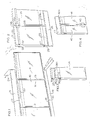
- Figure 1 illustrates a chain of bags with the bags preferably formed of a thin polyethylene material and attached to each other in a side-by-side relationship. Bags are shown at 10 and 11 having heat sealed side seams 14 and 15, and a cross section of the bag 9 is shown to illustrate sidewalls 12 and 13. The bottom is closed along a heat sealed seam 16.
- rib and groove elements 17 and 18 Adjacent the top of the bag on confronting faces are pressure interlocking rib and groove elements 17 and 18.
- the rib and groove elements are separable in using the bag by pulling apart flanges 23 and 24 at the top of the bag.
- a strip 19 which is a continuation of the bag walls 12 and 13 below the bottom seam 16, extends along the bottom of the bags and is perforated below said seam by perforations 20.
- the side seams 14 and 15 extend slightly beyond sealed seam 16 into the the perforations 20 so that when the strip 19 is torn along said perforations, the bags in the chain become separated.
- a similar strip 21 which is a continuation of flange flap 24 and extends along the top of the bags and is perforated by perforations 22.
- the individual connected bags after their rib and groove elements have been pulled apart are filled and then the rib and groove elements are pressed together.
- the filled bags are then separated from the chain by tearing the strips 19 and 21 from the chain which release the individual bags from the chain. Until the strips are torn off, the bags are interconnected in a chain. It is also possible that the user may wish to fill the individual bags after they have been separated from the chain. In that case the bags will be released by tearing the strips off the chain and each bag will be released to be taken individually and filled when the strips are progressively torn from the chain.
- the strips 19 and 21 are preferably of material integral with the bag material.
- bags 25 and 26 are shown interconnected into a chain.
- the bags are inverted and the rib and groove elements 27 are facing downwardly.
- the bottom edges of the bag, 30 and 31 (at the top in Fig. 2), remain unattached so that access to the interior of the bag is afforded for a filling machine.
- a double strip 28 has lines of perforations at 28a which may be torn off to separate the bags.
- An additional frangible connection link between the bags in the chain is shown at 34, but this may be omitted in some chain constructions where the bags are connected only by the double strip 28 each of which is a continuation of the respective bag walls.
- the link 34 may be formed by plastic softened by heat with the plastic supplied from the ribs 32 and 33 at 34a and 34b.
- ribs 32 and 33 which may be employed by the machine to support the bag. That is, the ribs have downwardly facing shoulders so that they can slide in recesses on the bag machine.
- frangible links 34 are divided into heat sealed areas 34a and 34b by cuts thereby reducing the size of the links 34 to a predetermined width which gives them the strength necessary to hold the bags in a chain, but the links 34 are breakable when the bags are pulled apart.
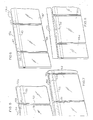
- FIG 3 illustrates another form of bag chain which may be utilized in a machine which has recesses to support the bag chain.
- the bags 36 of Figure 3 have a rib 38 along the top.
- the rib is carried on a flap 37 which is integral with the flange 36a, but with perforations 39 extending between the flange 36a and flap 37.
- the front flange 36c is pulled outwardly to separate rib and groove elements 36b and afforded access to the bag.
- the rib and groove elements are then pressed together to close the top.
- the top flap 37 is torn off the chain along the perforations 39, individual bags are removed from the chain.
- bags 40 and 41 of the chain are connected to each other by a tear strip 42 at the top and optionally additionally by a link 43 at the bottom of the bags.
- the link 43 is formed by a heat seal area which is reduced in width to afford the proper strength for attachment, but permit tearing.
- the strip 42 at the top has a line of perforations 42a which can be torn to free the individual bags.
- a chain of bags is formed with the bags interconnected by strips or attachment links laminated to the surface of the bag material.
- Adjacent bags 56 and 57 are attached to each other by small attachment strips 50 which are laminate d to the surface of flaps, such as front flaps 47 and 48 and rear flaps 47a and 48a.
- the strips 50 may be attached to the front flaps 47 and 48 or the rear flaps 47a and 48a.
- the links 50 may be formed of a small strip of polyethylene heat laminated to the surface area above the rib and groove profiles 49, and may be of a material lighter in weight than the bag material for facilitating tearing. Instead of being heat sealed, the links 50 may be adhesive backed.
- adjacent bags 51 and 52 having rib and groove profiles 53 on their inner confronting surfaces are attached to each other by a continuous strip 54 which is doubled over the top of the back flap 54a.
- the doubled strip 54 may be laminated to the bag material or attached thereto by adhesive.
- the laminated strip 54 leaves free a front flap 52a which can be pulled forward for opening the bag for filling.
- the bags are then torn apart by a longitudinal pull on the chain wherein the strip 54 breaks at the location between the bags.
- it may be of a material weaker than the bag material.
- a cut 55 may be placed in the strip at the location between the bags with the cut being of a predetermined length to leave an area of the strip sufficient to connect the bags but to permit easy breakage.
- the strip 54 may be peeled off the top of the bag to separate individual bags such as when the bags are fed through a machine.
- attachment structure While only one attachment structure may be employed between bags, duplicate attachments may be used both at the top and the bottom of the bag. A combination of the different forms of links may be employed at the top and bottom depending upon the circumstances of use.
- this strip When a continuous attached strip is employed, such as that illustrated in Figures 1 and 2, this strip may be formed simultaneously with the manufacture of the bag which will normally be made by a single operation in being extruded from a die. Where interconnecting means are attached to the bag, such as with the arrangements shown in Figures 6 and 7, these may be attached at the time the bags are cross-sealed.
- Figure 8 illustrates a continuous chain of bags interconnected by a continuous integral strip 59, which is a continuation of the rear flange and rear bag wall. Adjacent bags 55a and 56a are separated at their side edges, but the upper ends of the bags are joined by the strip 59 which is perforated from the rear flange by perforations 58. For filling, the front flap of the bags may be pulled forwardly, similarly to the arrangement shown in Figure 1, and when the bags are to be separated, the strip 59 will be torn off to separate the individual bags.
Abstract
Description
- The present invention relates to improvements in plastic bags and method of making plastic bags formed in a continuous bag chain where adjacent bags are joined by an interconnection and wherein the bags can be separated either manually or by a machine operation during an automatic filling procedure.
- The bags which are involved are thin plastic film bags which have sides and a bottom edge and at the upper end have a reclosable zipper lock structure. The zipper lock structure constitutes a set of interlocking rib and groove profiles. The lock structure is closable and the bag is closed by applying an opposed closure pressure progressively along the length of the profile elements. The lock structure and the bag is opened when the profiles are separated at either drawing them apart, such as by pulling flaps which extend above the profiles laterally or by longitudinal movement of one profile relative to another in such a manner that the profiles snap apart. Reclosable bags of the type described are disclosed, for example, in U.S. Patent Nos. Re 28,969, 3,338,284 and Re 29,208.
- In the manufacture of bags of the above type, they are typically made by the plastic being continuously extruded from a circular die to form an endless profile tube. However, the bags can be made from a folded flat film with interlocking profiles adjacent either end with said profiles either attached integrally or separately attached. In other words, the profiles can be formed integrally with the material of the bag or may be on strips which are then secured to the bag material. In the tubular form, the mating interlocking profiles are formed on the inner surface of the tube. The profiles are joined when the plastic has cooled sufficiently to eliminate distortion of the plastic. Subsequently, individual bags are formed by cross-seals at spaced intervals to form a seam at each of the side edges of each of the bags with the bags being simultaneously cut from the tube at said seam.
- In one commercially advantageous form, the bags are manufactured and are stored to be sold and shipped to the user who opens, fills and recloses the individual bags. These bags may be stacked in boxes, but in one preferred form, the bags are interconnected to each other in strip or chain form with individual bags torn off of the supply strip. This form of chain of bags is advantageously utilized in automatic filling and handling machines, and one arrangement for utilizing such a chain of bags is disclosed in US-Patent 4 490 959, where automatic machinery has been devised for feeding, opening, and reclosing the reclosable bags. Such mechanism utilizes a series of interconnected bags drawing them along a travel path through work stations of the machine. At one section of the machine, the individual bags are removed from the supply chain by being forcibly torn from the chain. Whether torn from the chain or otherwise disconnected, a relatively high speed production operation can occur by pulling the chain of bags from a supply source, either a roll or a box and having individual bags disconnected from the chain as they are handled by the machine.
- A significant feature of providing such a chain of bags is that the formation of the chain or interconnection of the bag be done simply without interfering with the manufacturing operation and without adversely affecting the strength and appearance of the bag. Also, whether the bags are forcibly torn from each other, or the interconnecting means is broken or separated by other arrangements as will be described herein, the bags must be separated without damage to them, and also separated rapidly and easily without slowing the high speed operation of the filling and closing machine.
- It is accordingly an object of the present i nvention to provide an improved method and bag chain wherein individual bags can be supplied in a chain and removed from the chain readily and easily and uniformly without endangering the integrity of the bags.
- A still further object of the invention is to provide an improved bag chain structure wherein the bags are reliably and simply attached to each other and are easily and readily removed from the chain.
- A further object of the invention is to provide an improved bag chain structure wherein the ease of separation of the bags can be controlled by the structure.
- A still further object of the invention is to provide an improved structure for the attachment of bags to each other to form a continuous chain wherein the structure serves to accurately align the adjacent bags to each other maintaining the interlocking rib and groove elements and the top and bottom edges in alignment.
- A feature of one form of the invention is to manufacture bags sequentially and provide a removable strip along one or both edges wherein the strip can be separated to sequentially release the bags such as by tearing the strip from the edge.
- Another feature of the invention in accordance with another form, is to provide a frangible strip attached to the bags wherein the strip is laminated to the bag material in a surface-to-surface engagement so that it is reinforced over the area of attachment but frangible in the area between the bags thus permitting a strip of uniform weight to be used. The strip can be formed of clear material which does not interfere with the appearance of the bag or can be formed of a decorative material which contributes to the structure and function and appearance of the bags.
- Other objects, advantages and features, as well as equivalent methods and structures, will become more apparent from the teaching of the principles of the invention in connection with the disclosure of the preferred embodiments in the specification, claims and drawings, in which:
-
- FIGURE 1 is a perspective view showing a section through one of a chain of bags constructed in accordance with the principles of the present invention;
- FIGURE 2 is a perspective view of another form of bag chain;
- FIGURE 3 is a fragmentary perspective view of another form of chain structure;
- FIGURE 4 is a perspective view of a further arrangement;
- FIGURE 5 is a perspective view illustrating removal of material for the use of the bag;
- FIGURE 6 is a perspective view of another form of bag arrangement;
- FIGURE 7 is a perspective view of still another form of bag arrangement; and
- FIGURE 8 is a perspective view of a further arrangement.
- Figure 1 illustrates a chain of bags with the bags preferably formed of a thin polyethylene material and attached to each other in a side-by-side relationship. Bags are shown at 10 and 11 having heat sealed
side seams bag 9 is shown to illustrate sidewalls 12 and 13. The bottom is closed along a heat sealedseam 16. - Adjacent the top of the bag on confronting faces are pressure interlocking rib and groove elements 17 and 18. The rib and groove elements are separable in using the bag by pulling apart
flanges 23 and 24 at the top of the bag. For purposes of interconnecting the bags in a continuous chain, a strip 19 which is a continuation of the bag walls 12 and 13 below thebottom seam 16, extends along the bottom of the bags and is perforated below said seam byperforations 20. Theside seams seam 16 into the theperforations 20 so that when the strip 19 is torn along said perforations, the bags in the chain become separated. - At the top is a
similar strip 21 which is a continuation of flange flap 24 and extends along the top of the bags and is perforated byperforations 22. - Thus, when utilizing the bags, the individual connected bags after their rib and groove elements have been pulled apart are filled and then the rib and groove elements are pressed together. The filled bags are then separated from the chain by tearing the
strips 19 and 21 from the chain which release the individual bags from the chain. Until the strips are torn off, the bags are interconnected in a chain. It is also possible that the user may wish to fill the individual bags after they have been separated from the chain. In that case the bags will be released by tearing the strips off the chain and each bag will be released to be taken individually and filled when the strips are progressively torn from the chain. Thestrips 19 and 21 are preferably of material integral with the bag material. - In the arrangement of Figure 2,
bags groove elements 27 are facing downwardly. The bottom edges of the bag, 30 and 31 (at the top in Fig. 2), remain unattached so that access to the interior of the bag is afforded for a filling machine. Adouble strip 28 has lines of perforations at 28a which may be torn off to separate the bags. An additional frangible connection link between the bags in the chain is shown at 34, but this may be omitted in some chain constructions where the bags are connected only by thedouble strip 28 each of which is a continuation of the respective bag walls. Thelink 34 may be formed by plastic softened by heat with the plastic supplied from theribs strip 28 is torn off,flanges 29 remain for separating the rib and andgroove elements 27. - Along the outer surfaces of the bag adjacent the bottom edges 30 and 31 are
ribs - It may be noted that the
frangible links 34 are divided into heat sealedareas links 34 to a predetermined width which gives them the strength necessary to hold the bags in a chain, but thelinks 34 are breakable when the bags are pulled apart. - In machine handling of a bag chain such as shown in Figure 2, the chain is pulled through a machine, the individual bags are filled between the separate edges 30 and 31, and the edges then jointed by a heat seal. The individual completed filled bags are separated by being forcibly pulled from the chain and by tearing off the
strip 28. - Figure 3 illustrates another form of bag chain which may be utilized in a machine which has recesses to support the bag chain. The
bags 36 of Figure 3 have arib 38 along the top. The rib is carried on aflap 37 which is integral with the flange 36a, but with perforations 39 extending between the flange 36a andflap 37. For filling the bag, thefront flange 36c is pulled outwardly to separate rib and groove elements 36b and afforded access to the bag. The rib and groove elements are then pressed together to close the top. When thetop flap 37 is torn off the chain along the perforations 39, individual bags are removed from the chain. - In Figure 4
bags tear strip 42 at the top and optionally additionally by alink 43 at the bottom of the bags. Thelink 43 is formed by a heat seal area which is reduced in width to afford the proper strength for attachment, but permit tearing. Thestrip 42 at the top has a line ofperforations 42a which can be torn to free the individual bags. - In Figure 6, a chain of bags is formed with the bags interconnected by strips or attachment links laminated to the surface of the bag material.
Adjacent bags rear flaps 47a and 48a. Thestrips 50 may be attached to thefront flaps rear flaps 47a and 48a. If the bags are formed of material such as polyethylene, thelinks 50 may be formed of a small strip of polyethylene heat laminated to the surface area above the rib andgroove profiles 49, and may be of a material lighter in weight than the bag material for facilitating tearing. Instead of being heat sealed, thelinks 50 may be adhesive backed. After the bags have been filled through the top and the ribs, and grooves rejoined, a longitudinal pull is exerted on the end bag, and thelink 50 connecting it to the next succeeding bag will break. Thestrip 50, while being lightweight and frangible lends some stiffness to the flaps when it is attached. - In the arrangement of Figures 5 and 7,
adjacent bags continuous strip 54 which is doubled over the top of the back flap 54a. The doubledstrip 54 may be laminated to the bag material or attached thereto by adhesive. Thelaminated strip 54 leaves free afront flap 52a which can be pulled forward for opening the bag for filling. The bags are then torn apart by a longitudinal pull on the chain wherein thestrip 54 breaks at the location between the bags. For this purpose, it may be of a material weaker than the bag material. If desired, acut 55 may be placed in the strip at the location between the bags with the cut being of a predetermined length to leave an area of the strip sufficient to connect the bags but to permit easy breakage. - As an alternate arrangement instead of the
strip 54 being torn, it may be peeled off the top of the bag to separate individual bags such as when the bags are fed through a machine. - While only one attachment structure may be employed between bags, duplicate attachments may be used both at the top and the bottom of the bag. A combination of the different forms of links may be employed at the top and bottom depending upon the circumstances of use.
- When a continuous attached strip is employed, such as that illustrated in Figures 1 and 2, this strip may be formed simultaneously with the manufacture of the bag which will normally be made by a single operation in being extruded from a die. Where interconnecting means are attached to the bag, such as with the arrangements shown in Figures 6 and 7, these may be attached at the time the bags are cross-sealed.
- Figure 8 illustrates a continuous chain of bags interconnected by a continuous
integral strip 59, which is a continuation of the rear flange and rear bag wall.Adjacent bags 55a and 56a are separated at their side edges, but the upper ends of the bags are joined by thestrip 59 which is perforated from the rear flange byperforations 58. For filling, the front flap of the bags may be pulled forwardly, similarly to the arrangement shown in Figure 1, and when the bags are to be separated, thestrip 59 will be torn off to separate the individual bags. - Thus, it will be seen that I have provided an improved method and structure for bag chains which is well suited for use in automatic bag handling machinery such as where the machinery pulls the bag chain from a supply source, opens, fills and recloses the bags. While separation will normally occur in the automatic machine, it may be done in a subsequent act by an eventual user.
- The preferred arrangements in accordance with the principles of the invention have been shown and described herein, but it will be understood that equivalent structures and methods utilizing the principles of the invention may be employed.
Claims (19)
a plurality of bags formed of a plastic film each having releasably interlocking rib and groove elements on co nfronting inner faces at the top, each closed by a side seam at each side edge and positioned in side-by-side relationship to form a chain; and a strip of material detachably connected to each of adjacent bags to form the chain and removable therefrom for separating individual bags from the chain.
wherein said strip of material is removably connected to the material of the bags along the longitudinal edge of the chain.
wherein said strip of material is continuous and coextensive with the chain formed by the plurality of bags.
wherein said strip of material is integral with the material of the bags and is attached thereto along a line of weakened resistance for manual separation from the chain formed by the plurality of bags.
wherein said line of weakened resistance is formed by a plurality of perforations extending parallel to said chain.
wherein said strip extends along the chain at the top edge of the bags.
wherein said strip extends along the edge of the chain formed by the plurality of bags which is at the bottom of the bags.
including a second means attaching the adjacent bags to each other spaced from said strip of material and being frangible to permit separation of the bags.
wherein said strip extends along the chain formed by the plurality of bags and the bags have an enlarged thickened ridge extending therealong for providing a support for the chain of bags when suspended by said strip.
a plurality of bags each formed of a plastic film with each having releasably interlocking rib and groove elements on confronting inner faces at the top of the bags, each closed by a side seam at each side, said bags located in side-by-side relationship to form a continuous chain;
and a strip of frangible material extending laterally between each two adjacent bags and secured to the surface of the bag so that said strip is strengthened by the material of the bag over the area where it is coextensive of the bag and the strip will separate between bags when a lateral breaking force is applied tending to separate the bags.
wherein said strip is continuous and coextensive with the chain of bags.
wherein said strip is laminated to the surface of the bag material.
wherein said strip is heat sealed to the bag material.
wherein said strip is attached to the bag material by an adhesive substance.
a plurality of bags formed of a plastic film each having releasably interlocking rib and groove elements on confronting inner faces adjacent the top edge of the bag, each closed by a side seam at each side, the bottom edges of the bags being separated for filling through the bottom;
and a strip of frangible material extending laterally between each two adjacent bags.
wherein said frangible material extends between adjacent bags at the lower end and another removable strip of material extends between bags at the upper end.
a plurality of bags formed of a plastic film each having releasably interlocking rib and groove elements on confronting inner faces at the top and each closed by said seams at each side with flaps above the fastener elements;
and a strip of interconnecting material extending laterally between each two adjacent bags attached to and doubled over one of the flaps.
wherein said strip is frangible between bags.
a plurality of bags formed of a plastic film each having releasably interconnecting rib and groove elements on confronting inner faces at the top, each closed by a side seam at each side edge and positioned in side-by-side relationship to form a chain;
the bottom edges of said bags being separated for filling;
a reinforcing rib extending along the bottom of the bags;
a frangible link interconnecting the bags in alignment with the reinforcing rib;
and a tear strip along the top interconnecting the bags and removable for access to the bags between the rib and groove elements and for separating the bags at the top.
Priority Applications (3)
| Application Number | Priority Date | Filing Date | Title |
|---|---|---|---|
| ES86115173T ES2015248B3 (en) | 1986-11-01 | 1986-11-01 | CHAIN OF ZIPPER CLOSURE BAGS WITH MEANS OF INTERCONNECTION WITH STARTING STRIP. |
| EP86115173A EP0266438B1 (en) | 1986-11-01 | 1986-11-01 | Zipper-lock bag chain with tearable strip interconnection means |
| DE8686115173T DE3671618D1 (en) | 1986-11-01 | 1986-11-01 | ZIPPER BAG CHAIN WITH TORN CONNECTOR. |
Applications Claiming Priority (1)
| Application Number | Priority Date | Filing Date | Title |
|---|---|---|---|
| EP86115173A EP0266438B1 (en) | 1986-11-01 | 1986-11-01 | Zipper-lock bag chain with tearable strip interconnection means |
Publications (2)
| Publication Number | Publication Date |
|---|---|
| EP0266438A1 true EP0266438A1 (en) | 1988-05-11 |
| EP0266438B1 EP0266438B1 (en) | 1990-05-30 |
Family
ID=8195557
Family Applications (1)
| Application Number | Title | Priority Date | Filing Date |
|---|---|---|---|
| EP86115173A Expired - Lifetime EP0266438B1 (en) | 1986-11-01 | 1986-11-01 | Zipper-lock bag chain with tearable strip interconnection means |
Country Status (3)
| Country | Link |
|---|---|
| EP (1) | EP0266438B1 (en) |
| DE (1) | DE3671618D1 (en) |
| ES (1) | ES2015248B3 (en) |
Cited By (6)
| Publication number | Priority date | Publication date | Assignee | Title |
|---|---|---|---|---|
| EP0780309A1 (en) * | 1995-12-18 | 1997-06-25 | Minigrip Flexible Packaging Limited | Method for filling a reclosable bag |
| EP2011740A1 (en) * | 2007-07-06 | 2009-01-07 | LEMO Maschinenbau GmbH | Apparatus bag on a spool |
| JP2018122939A (en) * | 2018-04-19 | 2018-08-09 | 株式会社生産日本社 | Cylindrical outer bag with fitting tool, cylindrical outer bag, outer bag filled with product, wound article or zigzag article of outer bag filled with product, their manufacturing method, and supplying method of bag body |
| JP2019189355A (en) * | 2019-03-06 | 2019-10-31 | 株式会社生産日本社 | Outer bag with product, wound article or zigzagged article of outer bag with product, producing method therefor, method for supplying bag body, cylindrical outer bag with fitting tool, and method for using cylindrical outer bag |
| US11154385B2 (en) | 2016-08-26 | 2021-10-26 | Vita Zahn Fabrik H. Rauter Gmbh & Co. Kg | Tooth unit and method for producing denture base |
| WO2022033647A1 (en) * | 2020-08-14 | 2022-02-17 | Schur Technology A/S | A web of bags with guide and bags of different materials |
Citations (6)
| Publication number | Priority date | Publication date | Assignee | Title |
|---|---|---|---|---|
| FR2009866A1 (en) * | 1968-05-08 | 1970-02-13 | Dow Chemical Co | |
| US4278198A (en) * | 1977-11-17 | 1981-07-14 | Baxter Travenol Laboratories, Inc. | Flexible collapsible container with a stiffening member |
| GB2109771A (en) * | 1981-11-19 | 1983-06-08 | Nigel Ervine Claxton | Bags and the manufacture of bags |
| FR2533892A1 (en) * | 1982-09-30 | 1984-04-06 | Flexico France Sarl | Chain of sacks made of plastic material |
| US4523918A (en) * | 1982-11-12 | 1985-06-18 | Minigrip, Inc. | Method of forming a bag chain |
| US4569083A (en) * | 1984-02-08 | 1986-02-04 | Basic Packaging Systems, Inc. | Chain of open mouth bags |
-
1986
- 1986-11-01 ES ES86115173T patent/ES2015248B3/en not_active Expired - Lifetime
- 1986-11-01 EP EP86115173A patent/EP0266438B1/en not_active Expired - Lifetime
- 1986-11-01 DE DE8686115173T patent/DE3671618D1/en not_active Expired - Fee Related
Patent Citations (6)
| Publication number | Priority date | Publication date | Assignee | Title |
|---|---|---|---|---|
| FR2009866A1 (en) * | 1968-05-08 | 1970-02-13 | Dow Chemical Co | |
| US4278198A (en) * | 1977-11-17 | 1981-07-14 | Baxter Travenol Laboratories, Inc. | Flexible collapsible container with a stiffening member |
| GB2109771A (en) * | 1981-11-19 | 1983-06-08 | Nigel Ervine Claxton | Bags and the manufacture of bags |
| FR2533892A1 (en) * | 1982-09-30 | 1984-04-06 | Flexico France Sarl | Chain of sacks made of plastic material |
| US4523918A (en) * | 1982-11-12 | 1985-06-18 | Minigrip, Inc. | Method of forming a bag chain |
| US4569083A (en) * | 1984-02-08 | 1986-02-04 | Basic Packaging Systems, Inc. | Chain of open mouth bags |
Cited By (7)
| Publication number | Priority date | Publication date | Assignee | Title |
|---|---|---|---|---|
| EP0780309A1 (en) * | 1995-12-18 | 1997-06-25 | Minigrip Flexible Packaging Limited | Method for filling a reclosable bag |
| EP2011740A1 (en) * | 2007-07-06 | 2009-01-07 | LEMO Maschinenbau GmbH | Apparatus bag on a spool |
| US11154385B2 (en) | 2016-08-26 | 2021-10-26 | Vita Zahn Fabrik H. Rauter Gmbh & Co. Kg | Tooth unit and method for producing denture base |
| JP2018122939A (en) * | 2018-04-19 | 2018-08-09 | 株式会社生産日本社 | Cylindrical outer bag with fitting tool, cylindrical outer bag, outer bag filled with product, wound article or zigzag article of outer bag filled with product, their manufacturing method, and supplying method of bag body |
| JP2019189355A (en) * | 2019-03-06 | 2019-10-31 | 株式会社生産日本社 | Outer bag with product, wound article or zigzagged article of outer bag with product, producing method therefor, method for supplying bag body, cylindrical outer bag with fitting tool, and method for using cylindrical outer bag |
| JP2022132582A (en) * | 2019-03-06 | 2022-09-08 | 株式会社生産日本社 | Outer bag with product, manufacturing method thereof, supply method of bag body, cylindrical outer bag with fitting tool, and application method of cylindrical outer bag |
| WO2022033647A1 (en) * | 2020-08-14 | 2022-02-17 | Schur Technology A/S | A web of bags with guide and bags of different materials |
Also Published As
| Publication number | Publication date |
|---|---|
| EP0266438B1 (en) | 1990-05-30 |
| DE3671618D1 (en) | 1990-07-05 |
| ES2015248B3 (en) | 1990-08-16 |
Similar Documents
| Publication | Publication Date | Title |
|---|---|---|
| US4630311A (en) | Zipper-lock bag chain with tearable strip interconnection means | |
| US4744674A (en) | Non-reclosable mechanically fillable and closable link bag structure and method | |
| US7101079B2 (en) | Resealable bag for filling with food product(s) and method | |
| US5023122A (en) | Easy open bag structure | |
| US6609828B2 (en) | Method of making reclosable packaging | |
| US4637060A (en) | Zipper-lock bag chain adapter for automatic loading and heat seal closing | |
| DE60109800T2 (en) | FILLING AND USING RE-BAGABLE BAGS | |
| US4654878A (en) | Plastic bag chain | |
| US5085031A (en) | Transverse zipper application for horizontal form, fill and seal machine | |
| US7165887B2 (en) | Resealable bag for filling with food product(s) and method | |
| US4894975A (en) | Method and apparatus for making reclosable bags with fastener strips in a form fill and seal machine | |
| US4832505A (en) | Tamper evident link bags | |
| US6523325B1 (en) | Apparatus for making resealable packages and reclosable seals | |
| EP0385323A1 (en) | Tamper evident package | |
| EP0054564B1 (en) | Blank belt | |
| EP0325993A1 (en) | Easy open bag structure | |
| IE48116B1 (en) | Bag of plastics foil | |
| US4523918A (en) | Method of forming a bag chain | |
| US6652436B1 (en) | Method of making tamper-evident package with slider zipper | |
| EP0266438A1 (en) | Zipper-lock bag chain with tearable strip interconnection means | |
| US20030169948A1 (en) | Reclosable packaging having hermetic zipper and related method of manufacture | |
| CA2640839C (en) | A resealable bag for filling with food product(s) and method | |
| CA1220172A (en) | Plastic bag chain | |
| US4584706A (en) | Chain of laterally interconnected bags | |
| CA1266029A (en) | Zipper-lock bag chain with tearable strip interconnection means |
Legal Events
| Date | Code | Title | Description |
|---|---|---|---|
| PUAI | Public reference made under article 153(3) epc to a published international application that has entered the european phase |
Free format text: ORIGINAL CODE: 0009012 |
|
| 17P | Request for examination filed |
Effective date: 19871024 |
|
| AK | Designated contracting states |
Kind code of ref document: A1 Designated state(s): BE CH DE ES FR GB GR IT LI SE |
|
| 17Q | First examination report despatched |
Effective date: 19880825 |
|
| GRAA | (expected) grant |
Free format text: ORIGINAL CODE: 0009210 |
|
| AK | Designated contracting states |
Kind code of ref document: B1 Designated state(s): BE CH DE ES FR GB IT LI SE |
|
| ET | Fr: translation filed | ||
| REF | Corresponds to: |
Ref document number: 3671618 Country of ref document: DE Date of ref document: 19900705 |
|
| ITF | It: translation for a ep patent filed |
Owner name: JACOBACCI & PERANI S.P.A. |
|
| PLBE | No opposition filed within time limit |
Free format text: ORIGINAL CODE: 0009261 |
|
| STAA | Information on the status of an ep patent application or granted ep patent |
Free format text: STATUS: NO OPPOSITION FILED WITHIN TIME LIMIT |
|
| 26N | No opposition filed | ||
| ITTA | It: last paid annual fee | ||
| PGFP | Annual fee paid to national office [announced via postgrant information from national office to epo] |
Ref country code: SE Payment date: 19930921 Year of fee payment: 8 |
|
| PGFP | Annual fee paid to national office [announced via postgrant information from national office to epo] |
Ref country code: FR Payment date: 19930922 Year of fee payment: 8 Ref country code: CH Payment date: 19930922 Year of fee payment: 8 |
|
| PGFP | Annual fee paid to national office [announced via postgrant information from national office to epo] |
Ref country code: GB Payment date: 19931022 Year of fee payment: 8 |
|
| PGFP | Annual fee paid to national office [announced via postgrant information from national office to epo] |
Ref country code: ES Payment date: 19931028 Year of fee payment: 8 |
|
| PGFP | Annual fee paid to national office [announced via postgrant information from national office to epo] |
Ref country code: BE Payment date: 19931215 Year of fee payment: 8 |
|
| PGFP | Annual fee paid to national office [announced via postgrant information from national office to epo] |
Ref country code: DE Payment date: 19931217 Year of fee payment: 8 |
|
| PG25 | Lapsed in a contracting state [announced via postgrant information from national office to epo] |
Ref country code: GB Effective date: 19941101 |
|
| PG25 | Lapsed in a contracting state [announced via postgrant information from national office to epo] |
Ref country code: SE Effective date: 19941102 Ref country code: ES Free format text: LAPSE BECAUSE OF EXPIRATION OF PROTECTION Effective date: 19941102 |
|
| PG25 | Lapsed in a contracting state [announced via postgrant information from national office to epo] |
Ref country code: LI Effective date: 19941130 Ref country code: CH Effective date: 19941130 Ref country code: BE Effective date: 19941130 |
|
| EAL | Se: european patent in force in sweden |
Ref document number: 86115173.6 |
|
| BERE | Be: lapsed |
Owner name: MINIGRIP EUROPE G.M.B.H. Effective date: 19941130 |
|
| GBPC | Gb: european patent ceased through non-payment of renewal fee |
Effective date: 19941101 |
|
| PG25 | Lapsed in a contracting state [announced via postgrant information from national office to epo] |
Ref country code: FR Effective date: 19950731 |
|
| REG | Reference to a national code |
Ref country code: CH Ref legal event code: PL |
|
| PG25 | Lapsed in a contracting state [announced via postgrant information from national office to epo] |
Ref country code: DE Effective date: 19950801 |
|
| EUG | Se: european patent has lapsed |
Ref document number: 86115173.6 |
|
| REG | Reference to a national code |
Ref country code: FR Ref legal event code: ST |
|
| REG | Reference to a national code |
Ref country code: ES Ref legal event code: FD2A Effective date: 20010301 |
|
| PG25 | Lapsed in a contracting state [announced via postgrant information from national office to epo] |
Ref country code: IT Free format text: LAPSE BECAUSE OF NON-PAYMENT OF DUE FEES;WARNING: LAPSES OF ITALIAN PATENTS WITH EFFECTIVE DATE BEFORE 2007 MAY HAVE OCCURRED AT ANY TIME BEFORE 2007. THE CORRECT EFFECTIVE DATE MAY BE DIFFERENT FROM THE ONE RECORDED. Effective date: 20051101 |