EP0266146A2 - Plaque d'ostéosynthése résorbable - Google Patents
Plaque d'ostéosynthése résorbable Download PDFInfo
- Publication number
- EP0266146A2 EP0266146A2 EP87309421A EP87309421A EP0266146A2 EP 0266146 A2 EP0266146 A2 EP 0266146A2 EP 87309421 A EP87309421 A EP 87309421A EP 87309421 A EP87309421 A EP 87309421A EP 0266146 A2 EP0266146 A2 EP 0266146A2
- Authority
- EP
- European Patent Office
- Prior art keywords
- plate
- bone
- screw hole
- unreinforced
- reinforcement
- Prior art date
- Legal status (The legal status is an assumption and is not a legal conclusion. Google has not performed a legal analysis and makes no representation as to the accuracy of the status listed.)
- Granted
Links
Images


Classifications
-
- A—HUMAN NECESSITIES
- A61—MEDICAL OR VETERINARY SCIENCE; HYGIENE
- A61L—METHODS OR APPARATUS FOR STERILISING MATERIALS OR OBJECTS IN GENERAL; DISINFECTION, STERILISATION OR DEODORISATION OF AIR; CHEMICAL ASPECTS OF BANDAGES, DRESSINGS, ABSORBENT PADS OR SURGICAL ARTICLES; MATERIALS FOR BANDAGES, DRESSINGS, ABSORBENT PADS OR SURGICAL ARTICLES
- A61L31/00—Materials for other surgical articles, e.g. stents, stent-grafts, shunts, surgical drapes, guide wires, materials for adhesion prevention, occluding devices, surgical gloves, tissue fixation devices
- A61L31/14—Materials characterised by their function or physical properties, e.g. injectable or lubricating compositions, shape-memory materials, surface modified materials
- A61L31/148—Materials at least partially resorbable by the body
-
- A—HUMAN NECESSITIES
- A61—MEDICAL OR VETERINARY SCIENCE; HYGIENE
- A61B—DIAGNOSIS; SURGERY; IDENTIFICATION
- A61B17/00—Surgical instruments, devices or methods, e.g. tourniquets
- A61B17/56—Surgical instruments or methods for treatment of bones or joints; Devices specially adapted therefor
- A61B17/58—Surgical instruments or methods for treatment of bones or joints; Devices specially adapted therefor for osteosynthesis, e.g. bone plates, screws, setting implements or the like
- A61B17/68—Internal fixation devices, including fasteners and spinal fixators, even if a part thereof projects from the skin
- A61B17/80—Cortical plates, i.e. bone plates; Instruments for holding or positioning cortical plates, or for compressing bones attached to cortical plates
-
- A—HUMAN NECESSITIES
- A61—MEDICAL OR VETERINARY SCIENCE; HYGIENE
- A61L—METHODS OR APPARATUS FOR STERILISING MATERIALS OR OBJECTS IN GENERAL; DISINFECTION, STERILISATION OR DEODORISATION OF AIR; CHEMICAL ASPECTS OF BANDAGES, DRESSINGS, ABSORBENT PADS OR SURGICAL ARTICLES; MATERIALS FOR BANDAGES, DRESSINGS, ABSORBENT PADS OR SURGICAL ARTICLES
- A61L31/00—Materials for other surgical articles, e.g. stents, stent-grafts, shunts, surgical drapes, guide wires, materials for adhesion prevention, occluding devices, surgical gloves, tissue fixation devices
- A61L31/04—Macromolecular materials
- A61L31/06—Macromolecular materials obtained otherwise than by reactions only involving carbon-to-carbon unsaturated bonds
-
- C—CHEMISTRY; METALLURGY
- C08—ORGANIC MACROMOLECULAR COMPOUNDS; THEIR PREPARATION OR CHEMICAL WORKING-UP; COMPOSITIONS BASED THEREON
- C08L—COMPOSITIONS OF MACROMOLECULAR COMPOUNDS
- C08L67/00—Compositions of polyesters obtained by reactions forming a carboxylic ester link in the main chain; Compositions of derivatives of such polymers
- C08L67/04—Polyesters derived from hydroxycarboxylic acids, e.g. lactones
-
- A—HUMAN NECESSITIES
- A61—MEDICAL OR VETERINARY SCIENCE; HYGIENE
- A61B—DIAGNOSIS; SURGERY; IDENTIFICATION
- A61B17/00—Surgical instruments, devices or methods, e.g. tourniquets
- A61B17/56—Surgical instruments or methods for treatment of bones or joints; Devices specially adapted therefor
- A61B17/58—Surgical instruments or methods for treatment of bones or joints; Devices specially adapted therefor for osteosynthesis, e.g. bone plates, screws, setting implements or the like
- A61B17/68—Internal fixation devices, including fasteners and spinal fixators, even if a part thereof projects from the skin
- A61B17/84—Fasteners therefor or fasteners being internal fixation devices
- A61B17/86—Pins or screws or threaded wires; nuts therefor
-
- A—HUMAN NECESSITIES
- A61—MEDICAL OR VETERINARY SCIENCE; HYGIENE
- A61B—DIAGNOSIS; SURGERY; IDENTIFICATION
- A61B17/00—Surgical instruments, devices or methods, e.g. tourniquets
- A61B2017/00004—(bio)absorbable, (bio)resorbable, resorptive
Definitions
- the present invention relates to a bone plate used as an aid for osteosynthesis and which is made of a material which will be absorbed in the body.
- Metallic bone plates and screws have been used for sometime in osteosynthesis to approximate fractured or broken bones in the body. These plates are generally made of materials such as stainless steel, chrome cobalt, titanium and various alloys of such metals.
- the bone plates are used to hold fractured bones in position so that they may heal in a proper manner.
- the bone plates offer advantages over the immobilization of the bone using only simple casting techniques.
- the use of internal fixation eliminates long periods of casting and allows early active joint movement which provides greater or earlier mobility to the patient.
- Bone plates fabricated from metal have been made in various designs. Generally, the design consists of a bar of the particular metal which is curved on the surface which will be placed against the bone. The plate has a number of screw holes in the plate and screws are introduced through the holes to secure the plate to the bone.
- U.S. Patent No. 3,463,148 discloses a metallic bone plate which has a substantially constant cross-sectional area. The plate has screw holes through the plate which are spaced on either side of a longitudinal center line. The metal in the area of the screw holes is thicker than the area of the metal between the screw holes.
- U.S. Patent No. 4,429,690 discloses a metal plate for the fixation of broken bones comprising two longitudinal bars joined by an array of humped bridges or crossed brackets evenly spaced along the length of the bars and having holes to set cortical screws. The design of this plate is indicated to resist fracture to a greater degree than the plates previously used.
- All of the above mentioned bone plates are designed to be fabricated from a relatively strong metal, such as stainless steel, chrome cobalt or titanium.
- the absorbable polymer from which the present bone plates are made does not have the strength of these metals.
- the strength of the absorbable polymer is significantly less than the strength of the metal from which the metallic bone plates are fabricated and, for that reason, the design of the metallic bone plates are not necessarily usable in a bone plate fabricated from an absorbable polymer.
- any bone plate it is necessary to minimize the thickness of any bone plate so that the plate will not sit too high on the bone and cause difficulty in the coverage of the bone plate with soft tissue following a surgical procedure. If the plate is too thick, it simply cannot be used. Similarly, anatomical restrictions also limit the width of a bone plate. The bone plate cannot be too much wider than the width of the bone for which it is designed to repair.
- the present invention provides a bone plate made from absorbable polymer which can be used in the fixation of bones without fear of the bone plate breaking.
- the present bone plate is constructed so that the stresses developed when the bone plate is used are relatively constant and are below the yield strength of the absorbable polymer from which the plate is fabricated.
- the area of the plate around the screw holes is reinforced in both the width and height of the plate. The reinforcement areas are optimized to insure that when the plate is subjected to the stresses generated upon fixation of the bone, the plate will not break and that the dimensions of the plate will be a minimum thickness and width.
- the bone plate of the present invention is made from the absorbable polylactide polymer disclosed in U.S. Patents 4,539,981 and 4,550,449.
- the polymer is a polylactide polymer which has a very high molecular weight and is strong enough to be fabricated into bone plates, screws and other internal fixation devices.
- the polymer will maintain its strength for a long enough period of time for the bone, onto which it is placed, to heal and it will be absorbed by the body over an extended period of time.
- the bone plate will lose its strength.
- the bone will be healing and be capable of assuming its normal load. There is no benefit to the patient in maintaining the bone plate supporting the fracture site after the bone has healed.
- metal bone plates on the bone after the bone has healed is considered to be detrimental because of possible corrosion and because the rigid metal plates prevent the bone from responding to normal load carrying activity.
- Metal plates are generally surgically removed between one and one-half to two years after implantation.
- the bone plate of the present invention could also be fabricated from other absorbable polymers which have the necessary strength and which have the characteristics of maintaining a strength in the body for the required time period.
- the particular design of the bone plate of the present invention is such that the bending stress at any point along the length of the bone plate does not exceed the level of stress through the center of a screw hole where the plate is fixed to the bone.
- the bending stress is determined by fixing the bone plate at one screw hole and bending the plate downward by loading weight at the next screw hole.
- the maximum stress at any point of the plate should not exceed the yield strength of the polymer when the bending load applied by the tightening of the screw is 300 Newtons.
- the yield strength of the polyactide polymer is 55 mpa.
- the stresses developed when the plate is loaded should be relatively constant throughout the plate.
- relatively constant is meant that the stress, developed at any given point of the plate does not vary by more than 20%, preferably not more than 10%, from the stress at any other point in the plate when the plate is loaded by affixing the plate to a bone.
- the area around the screw hole is reinforced both at the top of the screw hole and along the sides of the bone plate.
- the reinforcement is minimized in both the top and side to insure that the total bone plate is not excessively wide or thick.
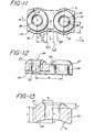
- T is the unreinforced plate thickness measured at the side edge of the plate
- W is one half the width of the unreinforced plate
- H is the height of the top reinforcement measured from the unreinforced top surface
- R is the radius of the side reinforcement of the plate measured from the centerline of a screw hole
- r is the radius of the top reinforcement measured along the centerline of a screw hole
- d ⁇ 2 is the distance from the centerline of the screw hole to the point where the top reinforcement intersects the unreinforced top of the plate d2 is the distance from the transverse centerline of the screw hole to the point where the side reinforcement intersects the unreinforced side of the plate
- L is the distance between adjacent screw holes measured from the screw hole centerlines
- the bone plate of the present invention may take different configurations.
- the plate shown in Figs. 1-5 is one typical configuration and the plate shown in Figs. 6-10 is a second typical and preferred configuration. Both of these plates can be considered to have a generally rectangular main portion with a curved or arcuate lower surface to be placed on the surface of the bone to be repaired. There are reinforcing areas in the side and top of the plate around the screw holes.
- the difference between the plates of Fig. 1-5 and Fig. 6-10 is the shape of the top reinforcement area.
- the bone plate 20 shown in Figs. 1-5 is of a sufficient length to bridge the fracture site in the bone.
- the plate has a number of screw holes 21 on either side of a center section 22.
- the lower surface 23 is arcuate to allow the plate to better fit the curvature of the bone to which the plate is attached.
- the unreinforced thickness of the plate is shown as T in the drawing Fig. 13 and the top reinforcement is shown as H.
- the unreinforced half width of the plate is shown as W and the radius of reinforced width as R in the drawings of Fig. 11.
- the centerline of the screw hole 29 or 30, in the direction through the thickness of the plate is referred to as the screw hole centerline.
- the centerline of the screw hole in the direction perpendicular to the length of the plate is referred to as the transverse centerline.
- the side reinforcing area can be considered to be a right circular cylinder of a radius R, Fig. 11, which is concentric with the screw hole and which intersects the side of the rectangular main portion of the plate at a distance d2 from the transverse centerline of the screw hole.
- the top reinforcing area can be considered to be a portion of a sphere, which has a radius which intersects the top of the unreinforced rectangular portion of the plate at a distance d ⁇ 2 from the screw hole centerline of the screw hole.
- the dimension of d ⁇ 2 is greater than the dimension of d2 in order to obtain the desired properties of the plate.
- the top portion of the sphere is flattened at the countersink 24 to reduce the total height of the plate.
- the top reinforcing element in the plate of Figs. 6-10 can be considered to be a portion of a right circular cylinder with its axis perpendicular to the length of the plate and extending through the side edges of the plate.
- the upper portion of the cylinder is removed for the countersink 24 and the top of the reinforcement area 28 has a flat surface 33 to reduce the thickness of the plate.
- a bone plate is affixed to a fractured bone on the tension side of the bone, i.e., on the convex side of the curve in the long dimension of the bone.
- the plate will be bent to conform to the curvature of the bone.
- the plate will be stressed as the screws are inserted into the bone. Assuming that the plate is first attached to the bone with a screw through screw hole 29, the maximum stress will be developed at the screw hole 29 when a screw placed through screw hole 30 is affixed to the bone.
- the side reinforcement 26 and the top reinforcement 27 prevents the plate from breaking at the screw hole 29.
- the lines S1 are located through the screw hole.
- the line S2a passes through the intersection of the side reinforcement and the unreinforced side of the plate around screw hole 30.
- the line S2 ⁇ a passes through the intersection of the top reinforcement area and the unreinforced top of the plate around the screw hole 30.
- the line S2 ⁇ b passes through the point where the top reinforcement around the next adjacent screw hole 29 intersects the unreinforced top of the plate.
- the line S2b passes through the point where the side reinforcement of the next adjacent screw hole 29 intersects the unreinforced side of the plate.
- the plate is first fixed at screw hole 29 and the load is applied at screw hole 30.
- bone plates have a length of between about 50 and 200 millimeters.
- the minimum length is dictated by the desirability to have at least four screw holes in the plate.
- the width of the bone plate is dependent on the size of the bone to which the plate will be attached.
- the unreinforced width of the plates are between 5 and 15 millimeters.
- the unreinforced height of the plates of the present invention are between 4 and 10 millimeters. The unreinforced height is measured from the bottom of the plate to the unreinforced surface at the top of the plate.
- the reinforcement in the width of the plate should be between 1 and 4 millimeters.
- the reinforcement in the height of the plate should be between 1 to 5 millimeters depending on the unreinforced thickness of the plate.
- the following Examples are show designs of various bone plates which are reinforced in different areas and show the effect of the reinforcement on the stresses that would be developed in the bone plate.
- the ultimate tensile strength of the polylactide polymer is about 70MPA.
- the stress at the screw hole exceeds the yield strength of the polymer and the plate would fail at the screw hole if implanted.
- Example II The stresses are calculated for a plate as in Example I.
- the plate has a uniform thickness of 6.4 millimeters.
- the results are shown in the following Table:
- the stress generated due to 535N loading around the screw hole is greater than the ultimate strength of the polymer.
- Example I A plate was fabricated as in Example I in the form shown in Figs. 1-5 of the drawings.
- the unreinforced thickness was 5.0 millimeters
- the top reinforcement was 4.8 millimeters in maximum thickness
- the side reinforcement was 3.0 millimeters in width.
- the stress was determined at a load 300N and of 535N as in Example I and the results as shown in the following Table:
- a bone plate was fabricated of the design shown in Fig. 6-10.
- the plate had a unreinforced thickness of 5 millimeters and a top reinforcement of 2.6 millimeters.
- the plate was 12 millimeters wide and had a side reinforcement of 3.2 millimeters, 1.6 millimeters on each side.
- the plate was 73.20 millimeters in length and had six screw holes spaced 12 millimeters from center line to center line with a space of 15 millimeters between the center holes.
- the plate was loaded with a force of 300 Newtons. in a three point bending configuration with the force applied at a screw hole.
- the stresses developed were:
Priority Applications (1)
| Application Number | Priority Date | Filing Date | Title |
|---|---|---|---|
| AT87309421T ATE83909T1 (de) | 1986-10-27 | 1987-10-26 | Resorbierbare knochenplatte. |
Applications Claiming Priority (2)
| Application Number | Priority Date | Filing Date | Title |
|---|---|---|---|
| US92323486A | 1986-10-27 | 1986-10-27 | |
| US923234 | 1986-10-27 |
Publications (3)
| Publication Number | Publication Date |
|---|---|
| EP0266146A2 true EP0266146A2 (fr) | 1988-05-04 |
| EP0266146A3 EP0266146A3 (en) | 1988-08-17 |
| EP0266146B1 EP0266146B1 (fr) | 1992-12-30 |
Family
ID=25448356
Family Applications (1)
| Application Number | Title | Priority Date | Filing Date |
|---|---|---|---|
| EP87309421A Expired - Lifetime EP0266146B1 (fr) | 1986-10-27 | 1987-10-26 | Plaque d'ostéosynthése résorbable |
Country Status (10)
| Country | Link |
|---|---|
| EP (1) | EP0266146B1 (fr) |
| JP (1) | JPH07102213B2 (fr) |
| KR (1) | KR960000622B1 (fr) |
| AT (1) | ATE83909T1 (fr) |
| AU (1) | AU602732B2 (fr) |
| CA (1) | CA1306156C (fr) |
| DE (1) | DE3783324T2 (fr) |
| ES (1) | ES2037093T3 (fr) |
| NZ (1) | NZ222159A (fr) |
| ZA (1) | ZA878025B (fr) |
Cited By (23)
| Publication number | Priority date | Publication date | Assignee | Title |
|---|---|---|---|---|
| DE3831657A1 (de) * | 1988-09-17 | 1990-03-22 | Boehringer Ingelheim Kg | Vorrichtung zur osteosynthese und verfahren zu ihrer herstellung |
| FR2642958A1 (fr) * | 1989-02-16 | 1990-08-17 | Louyot Comptoir Lyon Alemand | Systeme pour la mise en oeuvre d'interventions chirurgicales destinees par exemple au traitement des fractures de la colonne vertebrale ou de lesions degeneratives ou tumorales |
| EP0530585A2 (fr) * | 1991-09-03 | 1993-03-10 | Synthes AG, Chur | Vis et plaques résorbables autobloquantes pour l'immobilisation interne de fractures osseuses et la fixation d'un tendon à un os |
| US5290281A (en) * | 1992-06-15 | 1994-03-01 | Medicon Eg | Surgical system |
| US5336224A (en) * | 1992-11-30 | 1994-08-09 | Ace Medical Company | Bone fixation plate |
| FR2751203A1 (fr) * | 1996-07-22 | 1998-01-23 | Euros Sa | Plaque d'osteosynthese de rachis |
| WO1998009578A1 (fr) * | 1996-09-04 | 1998-03-12 | Anna Magrini | Processus de fabrication de plaques d'epaisseurs variables, destinees a l'osteosynthese |
| US5779706A (en) * | 1992-06-15 | 1998-07-14 | Medicon Eg | Surgical system |
| EP1088522A1 (fr) * | 1999-09-30 | 2001-04-04 | Sulzer Orthopedics Ltd. | Plaque d'ostéosynthèse avec plusieurs vis à os pour fixer une fracture |
| EP1247494A1 (fr) * | 2001-04-03 | 2002-10-09 | Inion Ltd. | Plaque d'ostéosynthèse |
| WO2008077482A1 (fr) * | 2006-12-20 | 2008-07-03 | Dietmar Wolter | Plaque support pour système de fixation osseuse |
| US10231768B2 (en) | 2003-05-30 | 2019-03-19 | DePuy Synthes Products, Inc. | Methods for implanting bone plates |
| US10335211B2 (en) | 2004-01-26 | 2019-07-02 | DePuy Synthes Products, Inc. | Highly-versatile variable-angle bone plate system |
| US10342586B2 (en) | 2003-08-26 | 2019-07-09 | DePuy Synthes Products, Inc. | Bone plate |
| US10624686B2 (en) | 2016-09-08 | 2020-04-21 | DePuy Synthes Products, Inc. | Variable angel bone plate |
| US10772665B2 (en) | 2018-03-29 | 2020-09-15 | DePuy Synthes Products, Inc. | Locking structures for affixing bone anchors to a bone plate, and related systems and methods |
| US10820930B2 (en) | 2016-09-08 | 2020-11-03 | DePuy Synthes Products, Inc. | Variable angle bone plate |
| US10905476B2 (en) | 2016-09-08 | 2021-02-02 | DePuy Synthes Products, Inc. | Variable angle bone plate |
| US10925651B2 (en) | 2018-12-21 | 2021-02-23 | DePuy Synthes Products, Inc. | Implant having locking holes with collection cavity for shavings |
| US11013541B2 (en) | 2018-04-30 | 2021-05-25 | DePuy Synthes Products, Inc. | Threaded locking structures for affixing bone anchors to a bone plate, and related systems and methods |
| US11026727B2 (en) | 2018-03-20 | 2021-06-08 | DePuy Synthes Products, Inc. | Bone plate with form-fitting variable-angle locking hole |
| US11259851B2 (en) | 2003-08-26 | 2022-03-01 | DePuy Synthes Products, Inc. | Bone plate |
| US11291484B2 (en) | 2004-01-26 | 2022-04-05 | DePuy Synthes Products, Inc. | Highly-versatile variable-angle bone plate system |
Families Citing this family (9)
| Publication number | Priority date | Publication date | Assignee | Title |
|---|---|---|---|---|
| CH673762A5 (fr) * | 1987-12-02 | 1990-04-12 | Synthes Ag | |
| FR2624744B1 (fr) * | 1987-12-18 | 1993-09-17 | Inst Nat Sante Rech Med | Procede de regulation d'un dispositif de ventilation artificielle et un tel dispositif |
| JP4727891B2 (ja) * | 2000-02-24 | 2011-07-20 | ストライカー インスツルメンツ | 生体吸収性接合板、締結具、ツール及びその使用方法 |
| BR0017270A (pt) * | 2000-06-26 | 2003-05-27 | Synthes Ag | Placa de osso para a osteosìntese e dispositivo de fixação com uma tal placa de osso |
| US7137985B2 (en) | 2003-09-24 | 2006-11-21 | N Spine, Inc. | Marking and guidance method and system for flexible fixation of a spine |
| US8979900B2 (en) | 2003-09-24 | 2015-03-17 | DePuy Synthes Products, LLC | Spinal stabilization device |
| US7637928B2 (en) | 2004-01-26 | 2009-12-29 | Synthes Usa, Llc | Variable angle locked bone fixation system |
| DE502004008607D1 (en) * | 2004-06-01 | 2009-01-15 | Synthes Gmbh | Osteosyntheseplatte |
| US8870871B2 (en) * | 2007-01-17 | 2014-10-28 | University Of Massachusetts Lowell | Biodegradable bone plates and bonding systems |
Citations (4)
| Publication number | Priority date | Publication date | Assignee | Title |
|---|---|---|---|---|
| FR2387636A1 (fr) * | 1977-04-22 | 1978-11-17 | Straumann Inst Ag | Plaque pour osteosynthese |
| EP0052998A1 (fr) * | 1980-11-21 | 1982-06-02 | Howmedica Inc. | Prothèse osseuse à rigidité controlée |
| GB2146535A (en) * | 1983-09-20 | 1985-04-24 | Materials Consultants Oy | Device for immobilising bone fractures |
| US4550449A (en) * | 1982-11-08 | 1985-11-05 | Johnson & Johnson Products Inc. | Absorbable bone fixation device |
-
1987
- 1987-10-13 NZ NZ222159A patent/NZ222159A/xx unknown
- 1987-10-26 DE DE8787309421T patent/DE3783324T2/de not_active Expired - Lifetime
- 1987-10-26 AU AU80149/87A patent/AU602732B2/en not_active Ceased
- 1987-10-26 EP EP87309421A patent/EP0266146B1/fr not_active Expired - Lifetime
- 1987-10-26 KR KR1019870011869A patent/KR960000622B1/ko not_active IP Right Cessation
- 1987-10-26 CA CA000550838A patent/CA1306156C/fr not_active Expired - Lifetime
- 1987-10-26 ZA ZA878025A patent/ZA878025B/xx unknown
- 1987-10-26 ES ES198787309421T patent/ES2037093T3/es not_active Expired - Lifetime
- 1987-10-26 AT AT87309421T patent/ATE83909T1/de not_active IP Right Cessation
- 1987-10-26 JP JP62268362A patent/JPH07102213B2/ja not_active Expired - Lifetime
Patent Citations (4)
| Publication number | Priority date | Publication date | Assignee | Title |
|---|---|---|---|---|
| FR2387636A1 (fr) * | 1977-04-22 | 1978-11-17 | Straumann Inst Ag | Plaque pour osteosynthese |
| EP0052998A1 (fr) * | 1980-11-21 | 1982-06-02 | Howmedica Inc. | Prothèse osseuse à rigidité controlée |
| US4550449A (en) * | 1982-11-08 | 1985-11-05 | Johnson & Johnson Products Inc. | Absorbable bone fixation device |
| GB2146535A (en) * | 1983-09-20 | 1985-04-24 | Materials Consultants Oy | Device for immobilising bone fractures |
Cited By (37)
| Publication number | Priority date | Publication date | Assignee | Title |
|---|---|---|---|---|
| DE3831657A1 (de) * | 1988-09-17 | 1990-03-22 | Boehringer Ingelheim Kg | Vorrichtung zur osteosynthese und verfahren zu ihrer herstellung |
| EP0360139A2 (fr) * | 1988-09-17 | 1990-03-28 | Boehringer Ingelheim Kg | Dispositif d'ostéosynthèse et son procédé de fabrication |
| EP0360139A3 (fr) * | 1988-09-17 | 1991-06-05 | Boehringer Ingelheim Kg | Dispositif d'ostéosynthèse et son procédé de fabrication |
| FR2642958A1 (fr) * | 1989-02-16 | 1990-08-17 | Louyot Comptoir Lyon Alemand | Systeme pour la mise en oeuvre d'interventions chirurgicales destinees par exemple au traitement des fractures de la colonne vertebrale ou de lesions degeneratives ou tumorales |
| EP0530585A2 (fr) * | 1991-09-03 | 1993-03-10 | Synthes AG, Chur | Vis et plaques résorbables autobloquantes pour l'immobilisation interne de fractures osseuses et la fixation d'un tendon à un os |
| EP0530585A3 (fr) * | 1991-09-03 | 1994-01-19 | Synthes Ag | |
| US5290281A (en) * | 1992-06-15 | 1994-03-01 | Medicon Eg | Surgical system |
| US5779706A (en) * | 1992-06-15 | 1998-07-14 | Medicon Eg | Surgical system |
| US5459298A (en) * | 1992-06-15 | 1995-10-17 | Tschakaloff; Alexander | Surgical system temperature controlled electric heating tool |
| US5607427A (en) * | 1992-06-15 | 1997-03-04 | Medicon Eg | Surgical system |
| US5336224A (en) * | 1992-11-30 | 1994-08-09 | Ace Medical Company | Bone fixation plate |
| FR2751203A1 (fr) * | 1996-07-22 | 1998-01-23 | Euros Sa | Plaque d'osteosynthese de rachis |
| EP0820730A1 (fr) * | 1996-07-22 | 1998-01-28 | Euros | Plaque d'ostéosynthèse de rachis |
| US6315852B1 (en) * | 1996-09-04 | 2001-11-13 | Anna Magrini | Production process of varying thickness osteosynthesis plates |
| WO1998009578A1 (fr) * | 1996-09-04 | 1998-03-12 | Anna Magrini | Processus de fabrication de plaques d'epaisseurs variables, destinees a l'osteosynthese |
| EP1088522A1 (fr) * | 1999-09-30 | 2001-04-04 | Sulzer Orthopedics Ltd. | Plaque d'ostéosynthèse avec plusieurs vis à os pour fixer une fracture |
| US6540746B1 (en) | 1999-09-30 | 2003-04-01 | Sulzer Orthopedics Ltd. | Bone plate for splinting a fracture at a bone with a plurality of bone screws |
| EP1247494A1 (fr) * | 2001-04-03 | 2002-10-09 | Inion Ltd. | Plaque d'ostéosynthèse |
| US10653466B2 (en) | 2003-05-30 | 2020-05-19 | DePuy Synthes Products, Inc. | Bone plate |
| US11419647B2 (en) | 2003-05-30 | 2022-08-23 | DePuy Synthes Products, Inc. | Bone plate |
| US10231768B2 (en) | 2003-05-30 | 2019-03-19 | DePuy Synthes Products, Inc. | Methods for implanting bone plates |
| US11259851B2 (en) | 2003-08-26 | 2022-03-01 | DePuy Synthes Products, Inc. | Bone plate |
| US10342586B2 (en) | 2003-08-26 | 2019-07-09 | DePuy Synthes Products, Inc. | Bone plate |
| US11291484B2 (en) | 2004-01-26 | 2022-04-05 | DePuy Synthes Products, Inc. | Highly-versatile variable-angle bone plate system |
| US10335211B2 (en) | 2004-01-26 | 2019-07-02 | DePuy Synthes Products, Inc. | Highly-versatile variable-angle bone plate system |
| WO2008077482A1 (fr) * | 2006-12-20 | 2008-07-03 | Dietmar Wolter | Plaque support pour système de fixation osseuse |
| US8460347B2 (en) | 2006-12-20 | 2013-06-11 | Dietmar Wolter | Load carrier for a bone fixation system |
| EA016252B9 (ru) * | 2006-12-20 | 2013-01-30 | Дитмар Вольтер | Несущий опорный элемент для системы фиксации костей |
| EA016252B1 (ru) * | 2006-12-20 | 2012-03-30 | Дитмар Вольтер | Несущий опорный элемент для системы фиксации костей |
| US10624686B2 (en) | 2016-09-08 | 2020-04-21 | DePuy Synthes Products, Inc. | Variable angel bone plate |
| US10820930B2 (en) | 2016-09-08 | 2020-11-03 | DePuy Synthes Products, Inc. | Variable angle bone plate |
| US10905476B2 (en) | 2016-09-08 | 2021-02-02 | DePuy Synthes Products, Inc. | Variable angle bone plate |
| US11529176B2 (en) | 2016-09-08 | 2022-12-20 | DePuy Synthes Products, Inc. | Variable angle bone plate |
| US11026727B2 (en) | 2018-03-20 | 2021-06-08 | DePuy Synthes Products, Inc. | Bone plate with form-fitting variable-angle locking hole |
| US10772665B2 (en) | 2018-03-29 | 2020-09-15 | DePuy Synthes Products, Inc. | Locking structures for affixing bone anchors to a bone plate, and related systems and methods |
| US11013541B2 (en) | 2018-04-30 | 2021-05-25 | DePuy Synthes Products, Inc. | Threaded locking structures for affixing bone anchors to a bone plate, and related systems and methods |
| US10925651B2 (en) | 2018-12-21 | 2021-02-23 | DePuy Synthes Products, Inc. | Implant having locking holes with collection cavity for shavings |
Also Published As
| Publication number | Publication date |
|---|---|
| ATE83909T1 (de) | 1993-01-15 |
| NZ222159A (en) | 1989-12-21 |
| CA1306156C (fr) | 1992-08-11 |
| KR960000622B1 (ko) | 1996-01-10 |
| EP0266146A3 (en) | 1988-08-17 |
| AU8014987A (en) | 1988-04-28 |
| KR880004791A (ko) | 1988-06-27 |
| AU602732B2 (en) | 1990-10-25 |
| ZA878025B (en) | 1989-06-28 |
| JPS63186642A (ja) | 1988-08-02 |
| JPH07102213B2 (ja) | 1995-11-08 |
| DE3783324T2 (de) | 1993-04-22 |
| DE3783324D1 (de) | 1993-02-11 |
| EP0266146B1 (fr) | 1992-12-30 |
| ES2037093T3 (es) | 1993-06-16 |
Similar Documents
| Publication | Publication Date | Title |
|---|---|---|
| US4905680A (en) | Absorbable bone plate | |
| EP0266146B1 (fr) | Plaque d'ostéosynthése résorbable | |
| US6001099A (en) | Bone plate with varying rigidity | |
| EP1707140B1 (fr) | Dispositf de fixation pour l'os naviculaire | |
| EP1707139B1 (fr) | Plaque de fixation du métatarse | |
| US6712820B2 (en) | Fixation plate system for dorsal wrist fracture fixation | |
| EP2099373B1 (fr) | Dispositif de fixation de plaque palmaire | |
| US6309393B1 (en) | Bone plate | |
| US4905679A (en) | Bone fracture reduction device and method of internal fixation of bone fractures | |
| US6508819B1 (en) | Method of dorsal wrist fracture fixation | |
| KR100308588B1 (ko) | 척추파열골절치료를위한내부전면고정시스템 | |
| AU675264B2 (en) | Bone fixation plate | |
| AU2010245194B2 (en) | Bone plate with a transfixation screw hole | |
| AU775910B2 (en) | Bone plate | |
| US7938849B2 (en) | Method for treating long bone fractures | |
| US6458133B1 (en) | Spinal fixation and retrieval device | |
| JP4421474B2 (ja) | 長骨骨幹端骨折用の髄内固定デバイス | |
| US20060015103A1 (en) | I-beam configuration bone plate | |
| EP1088521A2 (fr) | Appareil pour maintenir des parties osseuses dans une position relative spatiale donnée | |
| JPH0558340B2 (fr) | ||
| US20220280211A1 (en) | Plate for temporarily bridging fragments of a fracture | |
| WO2003020007A2 (fr) | Procede de fixation d'une fracture dorsale du poignet | |
| CA3213337A1 (fr) | Plaque d'osteotomie de nivellement du plateau tibial avec decalage |
Legal Events
| Date | Code | Title | Description |
|---|---|---|---|
| PUAI | Public reference made under article 153(3) epc to a published international application that has entered the european phase |
Free format text: ORIGINAL CODE: 0009012 |
|
| AK | Designated contracting states |
Kind code of ref document: A2 Designated state(s): AT BE CH DE ES FR GB IT LI NL SE |
|
| PUAL | Search report despatched |
Free format text: ORIGINAL CODE: 0009013 |
|
| AK | Designated contracting states |
Kind code of ref document: A3 Designated state(s): AT BE CH DE ES FR GB IT LI NL SE |
|
| 17P | Request for examination filed |
Effective date: 19890206 |
|
| RAP1 | Party data changed (applicant data changed or rights of an application transferred) |
Owner name: JOHNSON & JOHNSON HOSPITAL SERVICES, INC. |
|
| 17Q | First examination report despatched |
Effective date: 19911009 |
|
| RAP1 | Party data changed (applicant data changed or rights of an application transferred) |
Owner name: JOHNSON & JOHNSON CONSUMER PRODUCTS, INC. |
|
| GRAA | (expected) grant |
Free format text: ORIGINAL CODE: 0009210 |
|
| AK | Designated contracting states |
Kind code of ref document: B1 Designated state(s): AT BE CH DE ES FR GB IT LI NL SE |
|
| REF | Corresponds to: |
Ref document number: 83909 Country of ref document: AT Date of ref document: 19930115 Kind code of ref document: T |
|
| ITF | It: translation for a ep patent filed |
Owner name: SOCIETA' ITALIANA BREVETTI S.P.A. |
|
| REF | Corresponds to: |
Ref document number: 3783324 Country of ref document: DE Date of ref document: 19930211 |
|
| ET | Fr: translation filed | ||
| REG | Reference to a national code |
Ref country code: ES Ref legal event code: FG2A Ref document number: 2037093 Country of ref document: ES Kind code of ref document: T3 |
|
| PLBI | Opposition filed |
Free format text: ORIGINAL CODE: 0009260 |
|
| 26 | Opposition filed |
Opponent name: KARL LEIBINGER MEDIZINTECHNIK GMBH & CO.KG Effective date: 19930930 |
|
| NLR1 | Nl: opposition has been filed with the epo |
Opponent name: KARL LEIBINGER MEDIZINTECHNIK GMBH & CO.KG |
|
| EAL | Se: european patent in force in sweden |
Ref document number: 87309421.3 |
|
| PLBO | Opposition rejected |
Free format text: ORIGINAL CODE: EPIDOS REJO |
|
| PLBN | Opposition rejected |
Free format text: ORIGINAL CODE: 0009273 |
|
| STAA | Information on the status of an ep patent application or granted ep patent |
Free format text: STATUS: OPPOSITION REJECTED |
|
| 27O | Opposition rejected |
Effective date: 19960212 |
|
| NLR2 | Nl: decision of opposition | ||
| REG | Reference to a national code |
Ref country code: GB Ref legal event code: IF02 |
|
| PGFP | Annual fee paid to national office [announced via postgrant information from national office to epo] |
Ref country code: NL Payment date: 20061003 Year of fee payment: 20 |
|
| PGFP | Annual fee paid to national office [announced via postgrant information from national office to epo] |
Ref country code: SE Payment date: 20061004 Year of fee payment: 20 |
|
| PGFP | Annual fee paid to national office [announced via postgrant information from national office to epo] |
Ref country code: AT Payment date: 20061011 Year of fee payment: 20 |
|
| PGFP | Annual fee paid to national office [announced via postgrant information from national office to epo] |
Ref country code: DE Payment date: 20061019 Year of fee payment: 20 |
|
| PGFP | Annual fee paid to national office [announced via postgrant information from national office to epo] |
Ref country code: GB Payment date: 20061025 Year of fee payment: 20 |
|
| PGFP | Annual fee paid to national office [announced via postgrant information from national office to epo] |
Ref country code: CH Payment date: 20061027 Year of fee payment: 20 |
|
| PGFP | Annual fee paid to national office [announced via postgrant information from national office to epo] |
Ref country code: IT Payment date: 20061031 Year of fee payment: 20 |
|
| PGFP | Annual fee paid to national office [announced via postgrant information from national office to epo] |
Ref country code: ES Payment date: 20061124 Year of fee payment: 20 |
|
| PGFP | Annual fee paid to national office [announced via postgrant information from national office to epo] |
Ref country code: BE Payment date: 20061218 Year of fee payment: 20 |
|
| REG | Reference to a national code |
Ref country code: CH Ref legal event code: PFA Owner name: JOHNSON & JOHNSON CONSUMER PRODUCTS, INC. Free format text: JOHNSON & JOHNSON CONSUMER PRODUCTS, INC.#GRANDVIEW ROAD#SKILLMAN/NJ (US) -TRANSFER TO- JOHNSON & JOHNSON CONSUMER PRODUCTS, INC.#GRANDVIEW ROAD#SKILLMAN/NJ (US) |
|
| REG | Reference to a national code |
Ref country code: GB Ref legal event code: PE20 |
|
| REG | Reference to a national code |
Ref country code: CH Ref legal event code: PL |
|
| BE20 | Be: patent expired |
Owner name: *JOHNSON & JOHNSON CONSUMER PRODUCTS INC. Effective date: 20071026 |
|
| NLV7 | Nl: ceased due to reaching the maximum lifetime of a patent |
Effective date: 20071026 |
|
| REG | Reference to a national code |
Ref country code: ES Ref legal event code: FD2A Effective date: 20071027 |
|
| PG25 | Lapsed in a contracting state [announced via postgrant information from national office to epo] |
Ref country code: NL Free format text: LAPSE BECAUSE OF EXPIRATION OF PROTECTION Effective date: 20071026 |
|
| PG25 | Lapsed in a contracting state [announced via postgrant information from national office to epo] |
Ref country code: GB Free format text: LAPSE BECAUSE OF EXPIRATION OF PROTECTION Effective date: 20071025 Ref country code: ES Free format text: LAPSE BECAUSE OF EXPIRATION OF PROTECTION Effective date: 20071027 |
|
| PGFP | Annual fee paid to national office [announced via postgrant information from national office to epo] |
Ref country code: FR Payment date: 20061010 Year of fee payment: 20 |