EP0265943A2 - Radio telephone system - Google Patents
Radio telephone system Download PDFInfo
- Publication number
- EP0265943A2 EP0265943A2 EP87115900A EP87115900A EP0265943A2 EP 0265943 A2 EP0265943 A2 EP 0265943A2 EP 87115900 A EP87115900 A EP 87115900A EP 87115900 A EP87115900 A EP 87115900A EP 0265943 A2 EP0265943 A2 EP 0265943A2
- Authority
- EP
- European Patent Office
- Prior art keywords
- channel
- control
- communication
- signal
- receiver means
- Prior art date
- Legal status (The legal status is an assumption and is not a legal conclusion. Google has not performed a legal analysis and makes no representation as to the accuracy of the status listed.)
- Granted
Links
Images


Classifications
-
- H—ELECTRICITY
- H04—ELECTRIC COMMUNICATION TECHNIQUE
- H04M—TELEPHONIC COMMUNICATION
- H04M1/00—Substation equipment, e.g. for use by subscribers
- H04M1/72—Mobile telephones; Cordless telephones, i.e. devices for establishing wireless links to base stations without route selection
- H04M1/725—Cordless telephones
- H04M1/72502—Cordless telephones with one base station connected to a single line
- H04M1/72505—Radio link set-up procedures
- H04M1/72508—Radio link set-up procedures using a control channel
Definitions
- the present invention relates to a radio telephone system and, more particularly, to connection control between a base station and a plurality of mobile stations in the radio telephone system.
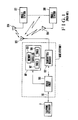
- a conventional radio telephone system comprises a base station 1 connected to a telephone exchanger 3 through a subscriber line 110, and a plurality of mobile stations 201 connected to the base station 1 through a radio channel.
- the base station 1 comprises a controller 101 having a microprocessor as a main component, a transmitter/receiver 102 for exchanging signals with the mobile stations 201 through a radio channel, and a hybrid circuit 103 including an interface circuit for interfacing data with the subscriber line 110 and a communication network.
- the radio channel comprises a control channel and communication channels.
- the controller 101 has a memory 106 and timers 107 and 108, and controls the transmitter/receiver 102, and the hybrid circuit 103 to control connection and communication between the base station 1 and the mobile stations 201 through a radio channel.
- a plurality of radio telephone sets having a given radio frequency band are simultaneously used in a relatively narrow area.
- a radio wave emitted from one radio telephone set can reach all other radio telephone sets.
- the radio telephone sets use common communication channels the number of which is smaller than that of mobile stations (e.g., 3 common channels).
- the remaining radio telephone sets can use one of communication channels #2 and #3 after they check whether the channels #2 and #3 are vacant.
- Fig. 2 is a flow chart of the stand-by control procedure of the base station 1.
- the controller 101 controls the transmitter/receiver 102 to switch a channel subjected to radio reception to a control channel (step 500).
- the timer 107 is set for, e.g., one second (step 501).
- the controller 101 repeatedly checks in step 502 whether a calling signal is received from the mobile station 201 and in step 503 whether a calling signal from the telephone exchanger 3 is detected until the time (one second) set in the timer 107 has elapsed (step 504).
- step 502 When the calling signal transmitted from the mobile station 201 to the base station 1 (referred to as calling signal from the mobile station) is detected in step 502, the flow advances to processing of the calling signal from the mobile station (a detailed description thereof will be omitted) to connect this mobile station 201 to the telephone exchanger 3 (step 508).
- calling signal from the mobile station referred to as calling signal from the mobile station
- step 503 When the calling signal transmitted from the telephone exchanger 3 to the base station 1 (referred to as calling signal from the telephone exchanger) is detected in step 503, processing of the calling signal from the telephone exchanger 3 (step 509) is performed for connecting the called mobile station 201 to the telephone exchanger 3 (this processing will be described in detail later).
- step 504 the controller 101 controls the transmitter/receiver 102 to switch the radio channel from the control channel to one arbitrary communication channel (step 505).
- the controller 101 determines in step 506 whether the communication channel is busy. If YES in step 506, the flow returns to step 500. However, if NO in step 506, the communication channel which is not busy is memorized in the memory 106 (step 507). Thereafter, the flow returns to step 500, and the above stand-by control procedure is repeated.
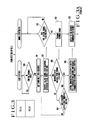
- Figs. 3A and 3B are flow charts of processing of the calling signal from the telephone exchanger 3 (step 509 in Fig. 2).
- the controller 101 in the base station 1 determines in step 600 whether other radio telephone sets use the control channel. If the control channel is not used, a predetermined time (e.g., 4 seconds) is set in the timer 108 in step 601. The controller 101 transmits the calling signal from the telephone exchanger to all the mobile stations 201 through the control channel (step 602).
- the controller 101 determines in step 603 whether the responses to the calling signal from the telephone exchanger have been received from the mobile stations 201.
- each mobile station 201 detects reception of the calling signal from the telephone exchanger in step 650, the response is transmitted to the base station 1 in step 651.
- the operation of the base station 1 in step 603 continues until the lapse of four seconds preset in the timer 108 is detected in step 604.
- the controller 101 in the base station 1 controls the transmitter/receiver 102 to switch the channel from the control channel to a given communication channel (step 605).
- the base station 1 receives a ringing signal of a 16-Hz intermittent signal from the telephone exchanger 3 and transmits a bell signal through the communication channel as long as the ringing signal is received (steps 606 and 607).
- the controller 101 then waits for an off-hook signal (step 608).
- each mobile station 201 the bell rings when the bell signal is received (steps 653 to 655), thereby causing a user to off-hook the mobile telephone set (step 656).
- the mobile station 201 detects the off-hook state (step 656), the mobile station 201 transmits an off-hook signal to the base station 1 (step 657).
- the off-hook signal is received by the base station 1 (step 608). Thereafter, exchange of the communication signal using the assigned communication channel is performed between the base station 1 and the mobile station 201.
- the controller 101 controls the transmitter/receiver 102 to switch the control and communication channels every predetermined time interval, thereby monitoring reception of the calling signal from the mobile station 201 and monitoring of the vacant communication channel. Therefore, when the calling signal is transmitted from the mobile station 201 to the base station 1 while the base station 1 monitors the vacant communication channel (steps 505 to 507 in Fig. 2), the base station 1 cannot immediately detect the calling signal from the mobile station until the channel is switched to the control channel (steps 500 to 502 in Fig. 2).
- a call is made from the telephone exchanger 3 when one, e.g., 201(A) of the plurality of mobile stations 201 is kept deenergized, that is, turns off its power switch.
- the mobile station 201(A) can detect the call by ringing of the bells of other mobile stations, i.e., the mobile station 201(B) and the like. Since the base station 1 and other mobile stations such as the station 201(B) are switched to a communication channel, the mobile station 201(A) cannot be connected to the base station 1. Therefore, the mobile station 201(A) cannot participate in communication in response to the call from the telephone exchanger 3.
- a radio telephone system including a base station connected to a telephone exchanger and a plurality of mobile stations connected to the base station through a radio channel having a control channel and a predetermined number of communication channels, wherein said base station comprises: a transmitter/receiver for transmitting/receiving a control signal through the control channel and a communication signal through the communication channel; a receiver for detecting a vacant one of the predetermined number of communication channels and for monitoring a calling signal transmitted from a given one of the mobile stations through the control channel; and a controller for performing both connection control and communication control through the radio channel by controlling the transmitter/receiver and the receiver, such that, in at least a stand-by mode, the receiver detects a vacant communication channel and the transmitter/receiver detects a control signal transmitted through the control channel.
- the receiver In the stand-by mode of the base station, the receiver detects the vacant communication channel, and the transmitter/receiver detects the control signal transmitted through the control channel. Therefore, a call from any mobile station any time can be immediately detected.
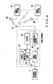
- FIG. 4 shows the overall arrangement of the radio telephone system according to an embodiment of the present invention.
- the same reference numerals as in Fig. 1 denote the same parts in Fig. 4.
- a radio telephone system shown in Fig. 4 comprises a base station 10 connected to a telephone exchanger 3 through a subscriber line 110 and a plurality of mobile stations 201 connected to the base station 10 through a radio channel.
- the base station 10 comprises a controller 101 ⁇ having a microprocessor as a main circuit component, a transmitter/receiver 102 for exchanging signals with the mobile station 201 through an antenna 105 and the radio channel, a receiver 104 for receiving a signal from the antenna 105, and a hybrid circuit 103.
- the receiver 104 detects a vacant one of a predetermined number of communication channels arranged in the radio channel and monitors a calling signal transmitted from the mobile station 201 through the control channel.
- the controller 101 ⁇ incorporates a memory 106 for storing data concerning vacant communication channel and a timer 108. In at least the stand-by mode, the controller 101 ⁇ controls to cause the receiver 104 to monitor and search for the vacant communication channels and to cause the transmitter/receiver 102 to detect a control signal transmitted through the control channel.
- Fig. 5 is a flow chart for explaining the stand-by operation of the base station 10
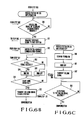
- Fig. 6A is a flow chart for explaining the calling connection operation of the base station 10
- Fig. 6B is a flow chart for explaining the calling connection operation of a mobile station with power ON or an ON mobile station
- Fig. 6C is a flow chart for explaining a calling connection operation of a mobile station with power OFF or an OFF mobile station.
- the base station 10 is set in the stand-by mode upon its energization.
- the controller 101 ⁇ switches the transmitter/receiver 102 to the control channel and the receiver 104 to a given communication channel (step 200), and the flow advances to step 201.
- step 201 the controller 101 ⁇ determines whether at least one mobile station 201 transmits the calling signal from the mobile station. If YES in step 201, the flow advances to step 202. In step 202, processing of the calling signal from the mobile station is performed. However, if NO in step 201, the flow advances to step 203. A detailed description of processing of the calling signal from the mobile station will be omitted.
- step 203 determines in step 203 whether the calling signal from the telephone exchanger 3 is detected. If YES in step 203, the flow advances to step> 204. In step 204, processing of the calling signal from the telephone exchanger 3 is performed. This processing will be described in detail later. However, if NO in step 203, the flow advances to step 205.
- the controller 101 ⁇ determines in step 205 whether an arbitrarily selected communication channel is busy.
- step 205 If YES in step 205, the flow returns to step 200. However, if NO in step 205, the flow advances to step 206.
- step 206 the vacant communication channel is memorized in the memory 106, and the flow returns to step 200.
- the controller 101 ⁇ is then set in the stand-by mode.
- reception operation (step 201) of the transmitter/receiver 102 and the reception operation (step 205) of the receiver 104 are simultaneously performed. Therefore, even during the vacant communication channel detection by repeating reception of the calling signals in units of the communication channels, processing of the calling signal from the mobile station (step 202) can be performed if a calling signal from any mobile station 201 is detected.
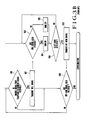
- the controller 101 ⁇ determines in step 300 whether the control channel is not used. If NO in step 300, the controller 101 ⁇ sets the timer 108 for 4 seconds in step 301. The base station 10 transmits the calling signal to all mobile stations 201 in step 302. The controller 101 ⁇ waits for responses from the mobile stations until 4 seconds set in the timer 108 have elapsed (steps 303 and 304). As shown in Fig. 6B, when the calling signal is received by the mobile stations 201 excluding the OFF mobile station 201(A) (step 350), the responses are transmitted from the ON mobile stations 201 to the base station 1 (step 351).
- the channels are switched from the control channel to a given communication channel in the transmitter/receiver 102 and from the communication channel to the control channel in the receiver 104, respectively.
- a communication channel assignment signal is transmitted from the base station 10 to the mobile stations 201 which have responded to the calling signal, and, therefore, the channel of each mobile station 201 is switched to the assigned communication channel (step 352).
- the base station 10 receives a ringing signal as a 16-Hz intermittent signal from the telephone exchanger 3 and transmits the bell signal to the mobile stations 201 through the assigned communication channel in response to the ringing signal while the ringing signal is "ON" (steps 306 and 307).
- the base station 10, i.e., the controller 101 ⁇ waits for the calling signal from the mobile station through the control channel (step 308) and the off-hook signal through a communication channel (step 309).
- the ON mobile station, e.g., 201(B) and the OFF mobile station, e.g., 201(A) are operated according to difference sequences, as shown in Figs. 6B and 6C, respectively.
- the ON mobile station 201(B) When the ON mobile station 201(B) receives the bell signal, the bell rings intermittently (steps 353 to 355) to cause the user to off-hook the radio mobile telephone set.
- the ON mobile station 201(B) transmits the off-hook signal to the base station 10 in step 357.
- the base station 10 receives the off-hook signal (step 309 in Fig. 6A). Therefore, the communication signal is exchanged between the base station 1 and the mobile station 201(B).
- the above operations are the same as those of the conventional radio telephone system.
- the user judges that it is convenient for him or her to use the OFF mobile station 201(A) after he or she has heard ringing of the ON mobile station 201(B) in steps 353 to 355, the user can turn on the power switch of the mobile station 201(A) (step 360) and off-hooks (step 361).
- the mobile station 201(A) transmits the calling signal through the control channel (step 362) and waits for a response to the calling signal in step 363.
- the receiver 104 of the base station 10 receives this calling signal.
- the base station 10 receives the calling signal from the mobile station 201(A) (step 308) instead of the off-hook signal (step 309).
- the controller 101 ⁇ switches the channel of the transmitter 102 from the communication channel to the control channel in step 310. Thereafter, the same procedures as in the conventional techniques are performed.
- the communication channel of the radio channel is set between the base station 10 and the mobile station 201(A), and communication is allowed.
- the receiver 104 is arranged in the base station 10 in addition to the transmitter/receiver 102 to detect a vacant one of the predetermined number of communication channels and to monitor the calling signal from the mobile station by using the control channel.
- the stand-by mode an arbitrary call made any time at any mobile station 201 can be immediately detected.
- a radio channel can be formed between the base station 10 and this mobile station 201. In this case, unlike in the conventional system wherein the base station waits for the calling signal by alternately switching the control and the communication channels, stand-by control can be simplified.
- the radio channel can be formed between the base station 10 and the mobile station 201 while the base station 10 waits for the off-hook signal from the mobile station 201 in response to the calling signal from the telephone exchanger 3. Since even an OFF mobile station (201(A)) can be used for communication after the user hears ringing of other mobile stations (201(B), etc.) and the OFF mobile station 201(A) is powered, the radio telephone system according to the present invention is very convenient.
Abstract
Description
- The present invention relates to a radio telephone system and, more particularly, to connection control between a base station and a plurality of mobile stations in the radio telephone system.
- As shown in Fig. 1, a conventional radio telephone system comprises a
base station 1 connected to atelephone exchanger 3 through asubscriber line 110, and a plurality ofmobile stations 201 connected to thebase station 1 through a radio channel. - The
base station 1 comprises acontroller 101 having a microprocessor as a main component, a transmitter/receiver 102 for exchanging signals with themobile stations 201 through a radio channel, and ahybrid circuit 103 including an interface circuit for interfacing data with thesubscriber line 110 and a communication network. The radio channel comprises a control channel and communication channels. Thecontroller 101 has amemory 106 andtimers receiver 102, and thehybrid circuit 103 to control connection and communication between thebase station 1 and themobile stations 201 through a radio channel. - In a multi-access radio telephone system, a plurality of radio telephone sets having a given radio frequency band are simultaneously used in a relatively narrow area. A radio wave emitted from one radio telephone set can reach all other radio telephone sets. The radio telephone sets use common communication channels the number of which is smaller than that of mobile stations (e.g., 3 common channels). When a given radio telephone set is off-hooked using
communication channel # 1, the remaining radio telephone sets can use one of communication channels #2 and #3 after they check whether the channels #2 and #3 are vacant. - Stand-by and connection control procedures in the conventional radio telephone sets in the multi-access radio telephone system will be described with reference to Figs. 2 and 3.
- Fig. 2 is a flow chart of the stand-by control procedure of the
base station 1. Referring to Fig. 2, thecontroller 101 controls the transmitter/receiver 102 to switch a channel subjected to radio reception to a control channel (step 500). Thetimer 107 is set for, e.g., one second (step 501). Thecontroller 101 repeatedly checks instep 502 whether a calling signal is received from themobile station 201 and instep 503 whether a calling signal from thetelephone exchanger 3 is detected until the time (one second) set in thetimer 107 has elapsed (step 504). - When the calling signal transmitted from the
mobile station 201 to the base station 1 (referred to as calling signal from the mobile station) is detected instep 502, the flow advances to processing of the calling signal from the mobile station (a detailed description thereof will be omitted) to connect thismobile station 201 to the telephone exchanger 3 (step 508). - When the calling signal transmitted from the
telephone exchanger 3 to the base station 1 (referred to as calling signal from the telephone exchanger) is detected instep 503, processing of the calling signal from the telephone exchanger 3 (step 509) is performed for connecting the calledmobile station 201 to the telephone exchanger 3 (this processing will be described in detail later). - When the lapse of one second set in the
timer 107 is detected instep 504, thecontroller 101 controls the transmitter/receiver 102 to switch the radio channel from the control channel to one arbitrary communication channel (step 505). Thecontroller 101 determines instep 506 whether the communication channel is busy. If YES instep 506, the flow returns tostep 500. However, if NO instep 506, the communication channel which is not busy is memorized in the memory 106 (step 507). Thereafter, the flow returns tostep 500, and the above stand-by control procedure is repeated. - Figs. 3A and 3B are flow charts of processing of the calling signal from the telephone exchanger 3 (
step 509 in Fig. 2). Referring to Figs. 3A and 3B, in thebase station 1 in which the calling signal from thetelephone exchanger 3 is detected by forming a current loop with thesubscriber line 110, thecontroller 101 in thebase station 1 determines in step 600 whether other radio telephone sets use the control channel. If the control channel is not used, a predetermined time (e.g., 4 seconds) is set in thetimer 108 instep 601. Thecontroller 101 transmits the calling signal from the telephone exchanger to all themobile stations 201 through the control channel (step 602). Thecontroller 101 determines instep 603 whether the responses to the calling signal from the telephone exchanger have been received from themobile stations 201. When eachmobile station 201 detects reception of the calling signal from the telephone exchanger instep 650, the response is transmitted to thebase station 1 instep 651. The operation of thebase station 1 instep 603 continues until the lapse of four seconds preset in thetimer 108 is detected instep 604. When the responses are detected instep 603, or when the lapse of four seconds preset in thetimer 108 is detected instep 604, thecontroller 101 in thebase station 1 controls the transmitter/receiver 102 to switch the channel from the control channel to a given communication channel (step 605). - In this case, since a communication channel assignment signal is transmitted from the
base station 1 to themobile stations 201, the channel of eachmobile station 201 is switched to the assigned communication channel (step 652). - Subsequently, the
base station 1 receives a ringing signal of a 16-Hz intermittent signal from thetelephone exchanger 3 and transmits a bell signal through the communication channel as long as the ringing signal is received (steps 606 and 607). Thecontroller 101 then waits for an off-hook signal (step 608). - In each
mobile station 201, the bell rings when the bell signal is received (steps 653 to 655), thereby causing a user to off-hook the mobile telephone set (step 656). When themobile station 201 detects the off-hook state (step 656), themobile station 201 transmits an off-hook signal to the base station 1 (step 657). The off-hook signal is received by the base station 1 (step 608). Thereafter, exchange of the communication signal using the assigned communication channel is performed between thebase station 1 and themobile station 201. - In the conventional multi-access radio telephone system described above, the following problems are presented.
- In the stand-by mode of the
base station 1, thecontroller 101 controls the transmitter/receiver 102 to switch the control and communication channels every predetermined time interval, thereby monitoring reception of the calling signal from themobile station 201 and monitoring of the vacant communication channel. Therefore, when the calling signal is transmitted from themobile station 201 to thebase station 1 while thebase station 1 monitors the vacant communication channel (steps 505 to 507 in Fig. 2), thebase station 1 cannot immediately detect the calling signal from the mobile station until the channel is switched to the control channel (steps 500 to 502 in Fig. 2). - Assume that a call is made from the
telephone exchanger 3 when one, e.g., 201(A) of the plurality ofmobile stations 201 is kept deenergized, that is, turns off its power switch. The mobile station 201(A) can detect the call by ringing of the bells of other mobile stations, i.e., the mobile station 201(B) and the like. Since thebase station 1 and other mobile stations such as the station 201(B) are switched to a communication channel, the mobile station 201(A) cannot be connected to thebase station 1. Therefore, the mobile station 201(A) cannot participate in communication in response to the call from thetelephone exchanger 3. - It is an object of the present invention to eliminate the conventional drawbacks described above and to provide a radio telephone system, wherein a base station can detect a calling signal from a mobile station, which is generated any time in at least a stand-by mode.
- In order to achieve the above object of the present invention, there is provided a radio telephone system including a base station connected to a telephone exchanger and a plurality of mobile stations connected to the base station through a radio channel having a control channel and a predetermined number of communication channels, wherein said base station comprises: a transmitter/receiver for transmitting/receiving a control signal through the control channel and a communication signal through the communication channel; a receiver for detecting a vacant one of the predetermined number of communication channels and for monitoring a calling signal transmitted from a given one of the mobile stations through the control channel; and a controller for performing both connection control and communication control through the radio channel by controlling the transmitter/receiver and the receiver, such that, in at least a stand-by mode, the receiver detects a vacant communication channel and the transmitter/receiver detects a control signal transmitted through the control channel.
- In the stand-by mode of the base station, the receiver detects the vacant communication channel, and the transmitter/receiver detects the control signal transmitted through the control channel. Therefore, a call from any mobile station any time can be immediately detected.
-
- Fig. 1 is a block diagram of a conventional radio telephone system;
- Figs. 2, 3, 3A and 3B are flow charts for explaining the operation of the conventional radio telephone system shown in Fig. 1;
- Fig. 4 is a block diagram of a radio telephone system according to an embodiment of the present invention; and
- Figs. 5, 6A, 6B, and 6C are flow charts for explaining the operation of the radio telephone system shown in Fig. 4.
- A preferred embodiment of the present invention will be described in detail with reference to the accompanying drawings. Fig. 4 shows the overall arrangement of the radio telephone system according to an embodiment of the present invention. The same reference numerals as in Fig. 1 denote the same parts in Fig. 4. A radio telephone system shown in Fig. 4 comprises a
base station 10 connected to atelephone exchanger 3 through asubscriber line 110 and a plurality ofmobile stations 201 connected to thebase station 10 through a radio channel. - The
base station 10 comprises a controller 101ʹ having a microprocessor as a main circuit component, a transmitter/receiver 102 for exchanging signals with themobile station 201 through anantenna 105 and the radio channel, areceiver 104 for receiving a signal from theantenna 105, and ahybrid circuit 103. - The
receiver 104 detects a vacant one of a predetermined number of communication channels arranged in the radio channel and monitors a calling signal transmitted from themobile station 201 through the control channel. - The controller 101ʹ incorporates a
memory 106 for storing data concerning vacant communication channel and atimer 108. In at least the stand-by mode, the controller 101ʹ controls to cause thereceiver 104 to monitor and search for the vacant communication channels and to cause the transmitter/receiver 102 to detect a control signal transmitted through the control channel. - The operation of the radio telephone system shown in Fig. 4 will now be described.
- Fig. 5 is a flow chart for explaining the stand-by operation of the
base station 10, Fig. 6A is a flow chart for explaining the calling connection operation of thebase station 10, Fig. 6B is a flow chart for explaining the calling connection operation of a mobile station with power ON or an ON mobile station, and Fig. 6C is a flow chart for explaining a calling connection operation of a mobile station with power OFF or an OFF mobile station. - Referring to Fig. 5, the
base station 10 is set in the stand-by mode upon its energization. In this state, the controller 101ʹ switches the transmitter/receiver 102 to the control channel and thereceiver 104 to a given communication channel (step 200), and the flow advances to step 201. - In
step 201, the controller 101ʹ determines whether at least onemobile station 201 transmits the calling signal from the mobile station. If YES instep 201, the flow advances to step 202. Instep 202, processing of the calling signal from the mobile station is performed. However, if NO instep 201, the flow advances to step 203. A detailed description of processing of the calling signal from the mobile station will be omitted. - The controller 101ʹ determines in
step 203 whether the calling signal from thetelephone exchanger 3 is detected. If YES instep 203, the flow advances to step> 204. Instep 204, processing of the calling signal from thetelephone exchanger 3 is performed. This processing will be described in detail later. However, if NO instep 203, the flow advances to step 205. - The controller 101ʹ determines in
step 205 whether an arbitrarily selected communication channel is busy. - If YES in
step 205, the flow returns to step 200. However, if NO instep 205, the flow advances to step 206. - In
step 206, the vacant communication channel is memorized in thememory 106, and the flow returns to step 200. The controller 101ʹ is then set in the stand-by mode. - It should be noted that the reception operation (step 201) of the transmitter/
receiver 102 and the reception operation (step 205) of thereceiver 104 are simultaneously performed. Therefore, even during the vacant communication channel detection by repeating reception of the calling signals in units of the communication channels, processing of the calling signal from the mobile station (step 202) can be performed if a calling signal from anymobile station 201 is detected. - As shown in Fig. 6A, in the
base station 1 which detects the calling signal from thetelephone exchanger 3 on the basis of an output state of thehybrid circuit 103, the controller 101ʹ determines instep 300 whether the control channel is not used. If NO instep 300, the controller 101ʹ sets thetimer 108 for 4 seconds instep 301. Thebase station 10 transmits the calling signal to allmobile stations 201 instep 302. The controller 101ʹ waits for responses from the mobile stations until 4 seconds set in thetimer 108 have elapsed (steps 303 and 304). As shown in Fig. 6B, when the calling signal is received by themobile stations 201 excluding the OFF mobile station 201(A) (step 350), the responses are transmitted from the ONmobile stations 201 to the base station 1 (step 351). - When the
base station 10 receives the responses from the ONmobile stations 201 instep 303, or when four seconds set in thetimer 108 have elapsed instep 304, the channels are switched from the control channel to a given communication channel in the transmitter/receiver 102 and from the communication channel to the control channel in thereceiver 104, respectively. In this case, a communication channel assignment signal is transmitted from thebase station 10 to themobile stations 201 which have responded to the calling signal, and, therefore, the channel of eachmobile station 201 is switched to the assigned communication channel (step 352). - The
base station 10 receives a ringing signal as a 16-Hz intermittent signal from thetelephone exchanger 3 and transmits the bell signal to themobile stations 201 through the assigned communication channel in response to the ringing signal while the ringing signal is "ON" (steps 306 and 307). Thebase station 10, i.e., the controller 101ʹ waits for the calling signal from the mobile station through the control channel (step 308) and the off-hook signal through a communication channel (step 309). - The ON mobile station, e.g., 201(B) and the OFF mobile station, e.g., 201(A) are operated according to difference sequences, as shown in Figs. 6B and 6C, respectively.
- When the ON mobile station 201(B) receives the bell signal, the bell rings intermittently (
steps 353 to 355) to cause the user to off-hook the radio mobile telephone set. When off-hook is detected instep 356, the ON mobile station 201(B) transmits the off-hook signal to thebase station 10 instep 357. Thebase station 10 receives the off-hook signal (step 309 in Fig. 6A). Therefore, the communication signal is exchanged between thebase station 1 and the mobile station 201(B). The above operations are the same as those of the conventional radio telephone system. - The following operations are the characteristic features of the present invention. When the user judges that it is convenient for him or her to use the OFF mobile station 201(A) after he or she has heard ringing of the ON mobile station 201(B) in
steps 353 to 355, the user can turn on the power switch of the mobile station 201(A) (step 360) and off-hooks (step 361). As a result, the mobile station 201(A) transmits the calling signal through the control channel (step 362) and waits for a response to the calling signal instep 363. Thereceiver 104 of thebase station 10 receives this calling signal. In this case, thebase station 10 receives the calling signal from the mobile station 201(A) (step 308) instead of the off-hook signal (step 309). The controller 101ʹ switches the channel of thetransmitter 102 from the communication channel to the control channel instep 310. Thereafter, the same procedures as in the conventional techniques are performed. The communication channel of the radio channel is set between thebase station 10 and the mobile station 201(A), and communication is allowed. - According to the radio telephone system as described above, the
receiver 104 is arranged in thebase station 10 in addition to the transmitter/receiver 102 to detect a vacant one of the predetermined number of communication channels and to monitor the calling signal from the mobile station by using the control channel. In the stand-by mode, an arbitrary call made any time at anymobile station 201 can be immediately detected. A radio channel can be formed between thebase station 10 and thismobile station 201. In this case, unlike in the conventional system wherein the base station waits for the calling signal by alternately switching the control and the communication channels, stand-by control can be simplified. The radio channel can be formed between thebase station 10 and themobile station 201 while thebase station 10 waits for the off-hook signal from themobile station 201 in response to the calling signal from thetelephone exchanger 3. Since even an OFF mobile station (201(A)) can be used for communication after the user hears ringing of other mobile stations (201(B), etc.) and the OFF mobile station 201(A) is powered, the radio telephone system according to the present invention is very convenient.
Claims (5)
a base station connected to a telephone exchanger; and
a plurality of mobile stations connected to said base station through radio channels including a control channel and a predetermined number of communication channels,
said base station comprising:
transmitter/receiver means for receiving a control signal through said control channel and a communication signal through a given one of said communication channels;
receiver means for detecting a vacant one of said predetermined number of communication channels and monitoring a calling signal from a given one of said plurality of mobile stations, which is received through said control channel; and
control means for performing connection control and communication control,
wherein said control means controls such that, in at least a stand-by mode, said receiver means detects a vacant communication channel and said transmitter/receiver means detects a control signal transmitted from said given mobile station through said control channel.
said connector means comprising:
transmitter/receiver means for transmitting/receiving a control signal through said control channel and a communication signal through a given one of said communication channels;
receiver means for receiving the control signal through said control channel and the communication signal through said given communication channel; and
control means, including a memory and a timer, for controlling said transmitter/receiver means and said receiver means to perform connection control and communication control through said radio channel,
wherein said control means sets a channel of said transmitter/receiver means to said control channel to allow processing in response to a calling signal from a given one of the plurality of mobile stations and a channel of said receiver to a given one of said communication channels to allow monitoring of communication channels, causes said memory to store a vacant communication channel, waits for a calling signal from said radio telephone set or said telephone exchanger, sets a predetermined period of time in said timer when the calling signal from said telephone exchanger is received, transmits the calling signal from said telephone exchanger to all of said plurality of radio telephone sets, receives responses from at least one said plurality of telephone sets, switches the channel of said transmitter/receiver means to a given one of said communication channels and said receiver means to said control channel when the predetermined period of time set in said timer has elapsed, transmits a ringing signal to establish communication between a first off-hooked one of said plurality of telephone sets and said telephone exchanger, and switches the channel of said transmitter/receiver means to said control channel when said receiver means receives, in response to the ringing signal, a calling signal from a second one of said plurality of radio telephone sets which did not respond within the predetermined period of time, thereby establishing communication between said second radio telephone set and said telephone exchanger.
Applications Claiming Priority (2)
| Application Number | Priority Date | Filing Date | Title |
|---|---|---|---|
| JP61258748A JPH0815354B2 (en) | 1986-10-30 | 1986-10-30 | Wireless telephone equipment |
| JP258748/86 | 1986-10-30 |
Publications (3)
| Publication Number | Publication Date |
|---|---|
| EP0265943A2 true EP0265943A2 (en) | 1988-05-04 |
| EP0265943A3 EP0265943A3 (en) | 1989-08-16 |
| EP0265943B1 EP0265943B1 (en) | 1994-02-23 |
Family
ID=17324534
Family Applications (1)
| Application Number | Title | Priority Date | Filing Date |
|---|---|---|---|
| EP87115900A Expired - Lifetime EP0265943B1 (en) | 1986-10-30 | 1987-10-29 | Radio telephone system |
Country Status (7)
| Country | Link |
|---|---|
| US (1) | US4875231A (en) |
| EP (1) | EP0265943B1 (en) |
| JP (1) | JPH0815354B2 (en) |
| KR (1) | KR910002356B1 (en) |
| AU (1) | AU598049B2 (en) |
| CA (1) | CA1271223A (en) |
| DE (1) | DE3789135T2 (en) |
Cited By (5)
| Publication number | Priority date | Publication date | Assignee | Title |
|---|---|---|---|---|
| EP0350947A2 (en) * | 1988-07-15 | 1990-01-17 | Nec Corporation | Radio channel control method |
| EP0379332A2 (en) * | 1989-01-18 | 1990-07-25 | Sony Corporation | Cordless telephones |
| US5123043A (en) * | 1986-09-18 | 1992-06-16 | Sony Corporation | Radio communication method and system |
| US5239683A (en) * | 1989-10-31 | 1993-08-24 | Nec Corporation | Cellular telephone system capable of reducing im distortion at portable telephone |
| GB2296629A (en) * | 1994-12-28 | 1996-07-03 | Nec Corp | Cordless telephone system |
Families Citing this family (42)
| Publication number | Priority date | Publication date | Assignee | Title |
|---|---|---|---|---|
| JPS6489841A (en) * | 1987-09-30 | 1989-04-05 | Toshiba Corp | Radiotelephony system |
| US5210785A (en) * | 1988-02-29 | 1993-05-11 | Canon Kabushiki Kaisha | Wireless communication system |
| GB8907317D0 (en) * | 1989-03-31 | 1989-05-17 | Plessey Telecomm | Communications systems |
| JP2555904B2 (en) * | 1989-04-27 | 1996-11-20 | 日本電気株式会社 | Car phone system |
| GB8925552D0 (en) * | 1989-11-11 | 1990-01-04 | Plessey Telecomm | A method of an air registration of a cordless telephone with a base station |
| CA2041752A1 (en) * | 1990-05-02 | 1991-11-03 | Roland E. Williams | Private cellular telephone system |
| DE69231392T2 (en) * | 1991-06-06 | 2001-02-01 | Fujitsu Ltd | Connection management device for cellular phone |
| JPH0537464A (en) * | 1991-07-30 | 1993-02-12 | Nec Corp | Multiaccess cordless telephone system |
| CA2082244C (en) * | 1992-01-08 | 1996-09-03 | Samuel Rocco Paniccia Jr. | Two-handset cordless telephone system |
| US5392330A (en) * | 1992-01-08 | 1995-02-21 | Thomson Consumer Electronics, Inc. | Offset down conversion for a two-handset cordless telephone system |
| CA2085722C (en) * | 1992-01-08 | 1997-02-25 | Samuel Rocco Paniccia Jr. | Use of a vcxo in the base unit of a two-handset cordless telephone system |
| US5475867A (en) * | 1992-02-06 | 1995-12-12 | Itron, Inc. | Distributed supervisory control and data acquisition system |
| US5325420A (en) * | 1992-09-30 | 1994-06-28 | Fujitsu Limited | Cordless phone haaving a plurality of personal stations |
| BR9510818B1 (en) | 1994-02-24 | 2010-08-10 | mobile phone configured for remote activation and remote reprogramming. | |
| US5594782A (en) * | 1994-02-24 | 1997-01-14 | Gte Mobile Communications Service Corporation | Multiple mode personal wireless communications system |
| US5542115A (en) | 1994-06-24 | 1996-07-30 | Pioneer Tech Development Limited | Paging method and apparatus |
| US8982856B2 (en) | 1996-12-06 | 2015-03-17 | Ipco, Llc | Systems and methods for facilitating wireless network communication, satellite-based wireless network systems, and aircraft-based wireless network systems, and related methods |
| US7054271B2 (en) | 1996-12-06 | 2006-05-30 | Ipco, Llc | Wireless network system and method for providing same |
| US7079810B2 (en) * | 1997-02-14 | 2006-07-18 | Statsignal Ipc, Llc | System and method for communicating with a remote communication unit via the public switched telephone network (PSTN) |
| US6233327B1 (en) * | 1997-02-14 | 2001-05-15 | Statsignal Systems, Inc. | Multi-function general purpose transceiver |
| US7137550B1 (en) | 1997-02-14 | 2006-11-21 | Statsignal Ipc, Llc | Transmitter for accessing automated financial transaction machines |
| US6542497B1 (en) | 1997-03-11 | 2003-04-01 | Verizon Services Corp. | Public wireless/cordless internet gateway |
| FR2764763A1 (en) * | 1997-06-17 | 1998-12-18 | Philips Electronics Nv | TELEPHONE DEVICE COMPRISING A BASE STATION AND AT LEAST ONE HANDSET DEVICE |
| KR100258978B1 (en) | 1997-07-02 | 2000-06-15 | 윤종용 | Apparatus and methode for generating test address for testing dynamic memory by using self test circuit |
| US6914533B2 (en) * | 1998-06-22 | 2005-07-05 | Statsignal Ipc Llc | System and method for accessing residential monitoring devices |
| US6891838B1 (en) | 1998-06-22 | 2005-05-10 | Statsignal Ipc, Llc | System and method for monitoring and controlling residential devices |
| US8410931B2 (en) | 1998-06-22 | 2013-04-02 | Sipco, Llc | Mobile inventory unit monitoring systems and methods |
| US6914893B2 (en) | 1998-06-22 | 2005-07-05 | Statsignal Ipc, Llc | System and method for monitoring and controlling remote devices |
| US6437692B1 (en) | 1998-06-22 | 2002-08-20 | Statsignal Systems, Inc. | System and method for monitoring and controlling remote devices |
| US7103511B2 (en) | 1998-10-14 | 2006-09-05 | Statsignal Ipc, Llc | Wireless communication networks for providing remote monitoring of devices |
| US7263073B2 (en) * | 1999-03-18 | 2007-08-28 | Statsignal Ipc, Llc | Systems and methods for enabling a mobile user to notify an automated monitoring system of an emergency situation |
| US7650425B2 (en) | 1999-03-18 | 2010-01-19 | Sipco, Llc | System and method for controlling communication between a host computer and communication devices associated with remote devices in an automated monitoring system |
| US6836737B2 (en) | 2000-08-09 | 2004-12-28 | Statsignal Systems, Inc. | Systems and methods for providing remote monitoring of consumption for a utility meter |
| US7346463B2 (en) | 2001-08-09 | 2008-03-18 | Hunt Technologies, Llc | System for controlling electrically-powered devices in an electrical network |
| US8489063B2 (en) | 2001-10-24 | 2013-07-16 | Sipco, Llc | Systems and methods for providing emergency messages to a mobile device |
| US7480501B2 (en) | 2001-10-24 | 2009-01-20 | Statsignal Ipc, Llc | System and method for transmitting an emergency message over an integrated wireless network |
| US7424527B2 (en) * | 2001-10-30 | 2008-09-09 | Sipco, Llc | System and method for transmitting pollution information over an integrated wireless network |
| US7756086B2 (en) * | 2004-03-03 | 2010-07-13 | Sipco, Llc | Method for communicating in dual-modes |
| US8031650B2 (en) | 2004-03-03 | 2011-10-04 | Sipco, Llc | System and method for monitoring remote devices with a dual-mode wireless communication protocol |
| WO2006081206A1 (en) | 2005-01-25 | 2006-08-03 | Sipco, Llc | Wireless network protocol systems and methods |
| WO2006104887A2 (en) * | 2005-03-25 | 2006-10-05 | Schulein Robert B | Audio and data communications system |
| JP2008112670A (en) * | 2006-10-31 | 2008-05-15 | Omron Corp | Switch |
Citations (5)
| Publication number | Priority date | Publication date | Assignee | Title |
|---|---|---|---|---|
| WO1983002380A1 (en) * | 1981-12-21 | 1983-07-07 | Akerberg, Dag, E:Son | A method and an equipment for transmission of telephone calls to a portable, wireless telephone set |
| JPS60182824A (en) * | 1984-02-29 | 1985-09-18 | Nec Corp | Radio communication system |
| EP0189920A2 (en) * | 1985-01-31 | 1986-08-06 | Nec Corporation | Radio channel control method for mobile communication system |
| EP0205055A2 (en) * | 1985-05-30 | 1986-12-17 | Nec Corporation | Channel selection in a multichannel access radio communication system without occurrence of interference |
| EP0293014A2 (en) * | 1987-05-29 | 1988-11-30 | Nippon Telegraph And Telephone Corporation | Control station and radio communication network system comprising a connecting equipment unit operable in different modes |
Family Cites Families (8)
| Publication number | Priority date | Publication date | Assignee | Title |
|---|---|---|---|---|
| JPS5839423B2 (en) * | 1976-08-30 | 1983-08-30 | 日本電信電話株式会社 | Wireless line control method |
| JPS59181734A (en) * | 1983-03-30 | 1984-10-16 | Nec Corp | Radio telephone system |
| US4741019A (en) * | 1984-03-15 | 1988-04-26 | Sanyo Electric Co., Ltd. | Cordless telephone |
| GB2165127B (en) * | 1984-09-26 | 1988-04-07 | Philips Electronic Associated | Multiple access communications system |
| US4672601A (en) * | 1984-12-06 | 1987-06-09 | Motorola, Inc. | Duplex interconnect/dispatch trunked radio system |
| SE448199B (en) * | 1985-05-09 | 1987-01-26 | Ericsson Telefon Ab L M | INSTALLATION WITH MULTIPLE BERBARA, CORDLESS PHONE DEVICES |
| US4672658A (en) * | 1985-10-16 | 1987-06-09 | At&T Company And At&T Bell Laboratories | Spread spectrum wireless PBX |
| US4682367A (en) * | 1985-11-13 | 1987-07-21 | General Electric Company | Mobile radio communications system with join feature |
-
1986
- 1986-10-30 JP JP61258748A patent/JPH0815354B2/en not_active Expired - Fee Related
-
1987
- 1987-10-27 US US07/112,928 patent/US4875231A/en not_active Expired - Lifetime
- 1987-10-29 EP EP87115900A patent/EP0265943B1/en not_active Expired - Lifetime
- 1987-10-29 CA CA000550548A patent/CA1271223A/en not_active Expired - Lifetime
- 1987-10-29 DE DE3789135T patent/DE3789135T2/en not_active Expired - Fee Related
- 1987-10-29 AU AU80459/87A patent/AU598049B2/en not_active Ceased
- 1987-10-30 KR KR8712088A patent/KR910002356B1/en not_active IP Right Cessation
Patent Citations (5)
| Publication number | Priority date | Publication date | Assignee | Title |
|---|---|---|---|---|
| WO1983002380A1 (en) * | 1981-12-21 | 1983-07-07 | Akerberg, Dag, E:Son | A method and an equipment for transmission of telephone calls to a portable, wireless telephone set |
| JPS60182824A (en) * | 1984-02-29 | 1985-09-18 | Nec Corp | Radio communication system |
| EP0189920A2 (en) * | 1985-01-31 | 1986-08-06 | Nec Corporation | Radio channel control method for mobile communication system |
| EP0205055A2 (en) * | 1985-05-30 | 1986-12-17 | Nec Corporation | Channel selection in a multichannel access radio communication system without occurrence of interference |
| EP0293014A2 (en) * | 1987-05-29 | 1988-11-30 | Nippon Telegraph And Telephone Corporation | Control station and radio communication network system comprising a connecting equipment unit operable in different modes |
Non-Patent Citations (1)
| Title |
|---|
| PATENT ABSTRACTS OF JAPAN, vol. 10, no. 24 (E-377)[2081], 30th January 1986; & JP-A-60 182 824 (NIPPON DENKI K.K.) 18-09-1985 * |
Cited By (10)
| Publication number | Priority date | Publication date | Assignee | Title |
|---|---|---|---|---|
| US5123043A (en) * | 1986-09-18 | 1992-06-16 | Sony Corporation | Radio communication method and system |
| EP0350947A2 (en) * | 1988-07-15 | 1990-01-17 | Nec Corporation | Radio channel control method |
| EP0350947A3 (en) * | 1988-07-15 | 1992-04-29 | Nec Corporation | Radio channel control method |
| EP0379332A2 (en) * | 1989-01-18 | 1990-07-25 | Sony Corporation | Cordless telephones |
| EP0379332A3 (en) * | 1989-01-18 | 1992-04-29 | Sony Corporation | Cordless telephones |
| SG92603A1 (en) * | 1989-01-18 | 2002-11-19 | Sony Corp | Cordless telephones |
| US5239683A (en) * | 1989-10-31 | 1993-08-24 | Nec Corporation | Cellular telephone system capable of reducing im distortion at portable telephone |
| GB2296629A (en) * | 1994-12-28 | 1996-07-03 | Nec Corp | Cordless telephone system |
| US5724661A (en) * | 1994-12-28 | 1998-03-03 | Nec Corporation | Cordless telephone system which converts a protocol for call connection |
| GB2296629B (en) * | 1994-12-28 | 1999-06-09 | Nec Corp | Cordless telephone system |
Also Published As
| Publication number | Publication date |
|---|---|
| EP0265943A3 (en) | 1989-08-16 |
| EP0265943B1 (en) | 1994-02-23 |
| CA1271223A (en) | 1990-07-03 |
| AU598049B2 (en) | 1990-06-14 |
| US4875231A (en) | 1989-10-17 |
| KR910002356B1 (en) | 1991-04-20 |
| AU8045987A (en) | 1988-05-05 |
| JPS63111735A (en) | 1988-05-17 |
| JPH0815354B2 (en) | 1996-02-14 |
| DE3789135T2 (en) | 1994-06-30 |
| KR880005777A (en) | 1988-06-30 |
| DE3789135D1 (en) | 1994-03-31 |
Similar Documents
| Publication | Publication Date | Title |
|---|---|---|
| EP0265943B1 (en) | Radio telephone system | |
| EP0154288B1 (en) | Method of transmitting terminating call signals within a restricted duration and a base station and a portable unit for use in the same | |
| EP0213929B1 (en) | Radio telephone system control apparatus and method | |
| EP0445887B1 (en) | Method of optimising the transmission of idle beacon messages in a communications system and a communications system operable in accordance with the method | |
| US4409687A (en) | Arrangement and method for establishing radio communication in a system | |
| US4872205A (en) | Radio communication system having autonomously selected transmission frequencies | |
| US5748621A (en) | Digital mobile communication system | |
| US5737690A (en) | Method and apparatus for orienting a pluridirectional wireless interface | |
| EP0248351B1 (en) | Cordless telephone system | |
| JPH07303278A (en) | Radio base station operating in radiocommunication system and its control | |
| EP0218450B2 (en) | Control system of a radio telephone apparatus | |
| EP0214810B1 (en) | Radio telephone system control apparatus | |
| US5384827A (en) | Cordless telephone system capable of quickly establishing connection during call setup phase | |
| JP3278505B2 (en) | Digital radio telephone equipment | |
| EP0969434B1 (en) | Wireless terminal automatically alerting user upon wireless terminal entering a specified physical location | |
| JP2748806B2 (en) | Connection control method in mobile communication system | |
| JPS6094545A (en) | Mobile radio communication system | |
| KR0135963B1 (en) | Radio telephone system | |
| JP2663391B2 (en) | Line connection method | |
| JPH01223835A (en) | Cordless telephone set | |
| GB2035011A (en) | Radio communication system and method | |
| EP0843495A2 (en) | Method and system for the monitoring of the radio environment in a dect cordless system | |
| JPS60182824A (en) | Radio communication system | |
| JP2004254058A (en) | Mobile wireless unit and digital mobile communication system employing the same | |
| JPH10224847A (en) | Digital cordless phone |
Legal Events
| Date | Code | Title | Description |
|---|---|---|---|
| PUAI | Public reference made under article 153(3) epc to a published international application that has entered the european phase |
Free format text: ORIGINAL CODE: 0009012 |
|
| 17P | Request for examination filed |
Effective date: 19871029 |
|
| AK | Designated contracting states |
Kind code of ref document: A2 Designated state(s): DE GB IT NL SE |
|
| PUAL | Search report despatched |
Free format text: ORIGINAL CODE: 0009013 |
|
| RHK1 | Main classification (correction) |
Ipc: H04M 1/72 |
|
| AK | Designated contracting states |
Kind code of ref document: A3 Designated state(s): DE GB IT NL SE |
|
| 17Q | First examination report despatched |
Effective date: 19920122 |
|
| GRAA | (expected) grant |
Free format text: ORIGINAL CODE: 0009210 |
|
| AK | Designated contracting states |
Kind code of ref document: B1 Designated state(s): DE GB IT NL SE |
|
| PG25 | Lapsed in a contracting state [announced via postgrant information from national office to epo] |
Ref country code: IT Free format text: LAPSE BECAUSE OF FAILURE TO SUBMIT A TRANSLATION OF THE DESCRIPTION OR TO PAY THE FEE WITHIN THE PRE;WARNING: LAPSES OF ITALIAN PATENTS WITH EFFECTIVE DATE BEFORE 2007 MAY HAVE OCCURRED AT ANY TIME BEFORE 2007. THE CORRECT EFFECTIVE DATE MAY BE DIFFERENT FROM THE ONE RECORDED.SCRIBED TIME-LIMIT Effective date: 19940223 Ref country code: NL Effective date: 19940223 |
|
| REF | Corresponds to: |
Ref document number: 3789135 Country of ref document: DE Date of ref document: 19940331 |
|
| NLV1 | Nl: lapsed or annulled due to failure to fulfill the requirements of art. 29p and 29m of the patents act | ||
| PLBE | No opposition filed within time limit |
Free format text: ORIGINAL CODE: 0009261 |
|
| STAA | Information on the status of an ep patent application or granted ep patent |
Free format text: STATUS: NO OPPOSITION FILED WITHIN TIME LIMIT |
|
| EAL | Se: european patent in force in sweden |
Ref document number: 87115900.0 |
|
| 26N | No opposition filed | ||
| REG | Reference to a national code |
Ref country code: GB Ref legal event code: 732E |
|
| REG | Reference to a national code |
Ref country code: GB Ref legal event code: IF02 |
|
| PGFP | Annual fee paid to national office [announced via postgrant information from national office to epo] |
Ref country code: SE Payment date: 20020925 Year of fee payment: 16 |
|
| PGFP | Annual fee paid to national office [announced via postgrant information from national office to epo] |
Ref country code: GB Payment date: 20021023 Year of fee payment: 16 |
|
| PGFP | Annual fee paid to national office [announced via postgrant information from national office to epo] |
Ref country code: DE Payment date: 20021031 Year of fee payment: 16 |
|
| PG25 | Lapsed in a contracting state [announced via postgrant information from national office to epo] |
Ref country code: GB Free format text: LAPSE BECAUSE OF NON-PAYMENT OF DUE FEES Effective date: 20031029 |
|
| PG25 | Lapsed in a contracting state [announced via postgrant information from national office to epo] |
Ref country code: SE Free format text: LAPSE BECAUSE OF NON-PAYMENT OF DUE FEES Effective date: 20031030 |
|
| PG25 | Lapsed in a contracting state [announced via postgrant information from national office to epo] |
Ref country code: DE Free format text: LAPSE BECAUSE OF NON-PAYMENT OF DUE FEES Effective date: 20040501 |
|
| EUG | Se: european patent has lapsed | ||
| GBPC | Gb: european patent ceased through non-payment of renewal fee |
Effective date: 20031029 |