EP0265366A2 - An independent backup mode transfer method and mechanism for digital control computers - Google Patents
An independent backup mode transfer method and mechanism for digital control computers Download PDFInfo
- Publication number
- EP0265366A2 EP0265366A2 EP87630204A EP87630204A EP0265366A2 EP 0265366 A2 EP0265366 A2 EP 0265366A2 EP 87630204 A EP87630204 A EP 87630204A EP 87630204 A EP87630204 A EP 87630204A EP 0265366 A2 EP0265366 A2 EP 0265366A2
- Authority
- EP
- European Patent Office
- Prior art keywords
- signal
- transfer
- memory
- primary
- signal processor
- Prior art date
- Legal status (The legal status is an assumption and is not a legal conclusion. Google has not performed a legal analysis and makes no representation as to the accuracy of the status listed.)
- Granted
Links
Images


Classifications
-
- G—PHYSICS
- G05—CONTROLLING; REGULATING
- G05B—CONTROL OR REGULATING SYSTEMS IN GENERAL; FUNCTIONAL ELEMENTS OF SUCH SYSTEMS; MONITORING OR TESTING ARRANGEMENTS FOR SUCH SYSTEMS OR ELEMENTS
- G05B9/00—Safety arrangements
- G05B9/02—Safety arrangements electric
- G05B9/03—Safety arrangements electric with multiple-channel loop, i.e. redundant control systems
-
- G—PHYSICS
- G06—COMPUTING; CALCULATING OR COUNTING
- G06F—ELECTRIC DIGITAL DATA PROCESSING
- G06F11/00—Error detection; Error correction; Monitoring
- G06F11/07—Responding to the occurrence of a fault, e.g. fault tolerance
- G06F11/16—Error detection or correction of the data by redundancy in hardware
- G06F11/1666—Error detection or correction of the data by redundancy in hardware where the redundant component is memory or memory area
-
- G—PHYSICS
- G06—COMPUTING; CALCULATING OR COUNTING
- G06F—ELECTRIC DIGITAL DATA PROCESSING
- G06F11/00—Error detection; Error correction; Monitoring
- G06F11/07—Responding to the occurrence of a fault, e.g. fault tolerance
- G06F11/14—Error detection or correction of the data by redundancy in operation
- G06F11/1479—Generic software techniques for error detection or fault masking
- G06F11/1487—Generic software techniques for error detection or fault masking using N-version programming
-
- G—PHYSICS
- G06—COMPUTING; CALCULATING OR COUNTING
- G06F—ELECTRIC DIGITAL DATA PROCESSING
- G06F11/00—Error detection; Error correction; Monitoring
- G06F11/07—Responding to the occurrence of a fault, e.g. fault tolerance
- G06F11/16—Error detection or correction of the data by redundancy in hardware
- G06F11/20—Error detection or correction of the data by redundancy in hardware using active fault-masking, e.g. by switching out faulty elements or by switching in spare elements
Definitions
- This invention relates to transfer methods and mechanisms for digital control computers and, more particularly, to methods and mechanisms for transferring between a primary program memory and a backup program memory.
- the protection mechanism against generic software failures may take on many forms. For example, analog electronic computers may be used as backups for the primary digital system.
- An alternate solution involves the use of "in situ" alternate software which is switched on in case of detected generic software failure. In this case, the alternate software package is responsible for preventing loss of control of the system. This approach is quite cost effective, as the alternate software shares the same channel hardware, except for the program memory.
- the alternate software resident in a backup memory, can be engaged or disengaged by means of a transfer mechanism.
- a transfer mechanism Clearly, the reliability of the overall system in the presence of generic common mode software faults is dependent on the reliability and fault tolerance of the transfer mechanism. Therefore, the problem of protection from generic software failures is closely associated with the need for a reliable, independent, fault tolerant backup mode transfer mechanism for digital control computer systems.
- An object of the present invenion is to provide a transfer mechanism for transferring from primary program memory to an alternate or backup program memory which is independent of the channel's software. In other words, the transfer must occur via a hardware mechanism free of any software control.
- Another object of the present invention is to provide a transfer method and mechanism for transferring all channels to and from the backup mode with near simultaneity. It will be understood that this cannot be done by a central transfer controller because of the possibility of a common mode hardware failure.
- Another object of the present invention is to provide a transfer mechanism and method that provides clean, transient free transfers, i.e., the process of transfer between the primary and backup program memories must not create transients or leave incompleted routines or apparent failures behind which can lead to loss of the system after the transfer.
- Another object of the present invention is to provide a transfer mechanism and method for a redundant system in which unambiguous performance is provided in the presence of a power loss to a subset of channels.
- it should be permanent (until disengaged) for the control system as a whole in the presence of any power-off transients to a subset of channels that may follow.
- Another object of the present invention is to provide a transfer mechanism method responsive to the detected occurrances of the so-called generic software fault and/or the occurrance of direct user transfer requests.
- the transfer method and mechanism when activated, sends a non-maskable interrupt to all of the channel processor(s) when a majority of channels detect (by means of a sever request, a user request or any other mechanism) a generic software failure; each of the processors then sends an acknowledge signal in response to the non-maskable interrupt after concluding the machine cycle in which it is engaged at the time it receives the interrupt; the acknowledge signal, which is purely a hardware driven signal, is then used to transfer the signal processor's program memory from a primary program memory to a backup program memory.
- the transfer method and mechanism remembers the "system” state and returns the channel to the system state after each restoration of power to the channel. In this manner, the transfer method and mechanism provides a transient free transfer without loss of control (sever) by the system.
- the method and mechanism of the present invention utilizes the technique of providing a shadow or backup memory for the primary program memory.
- the program contained in the shadow backup memory will be different from the program in the primary memory in order to provide for protection against a generic software failure in the primary software.
- a key element of this approach is the use of a non-maskable interrupt which cannot be disabled by software. The transfer is clean and transient free. Once the system is transferred into backup mode it will remain in backup mode unless the operator, e.g., the pilot, disarms the backup system for a transient-free return to primary mode.
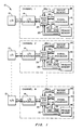
- Fig. 1 is an illustration of a redundant channel digital computer control system 10 having several redundant channels employed for system reliability.
- Each channel is illustrated generally as having three main components, i.e., input/output (I/O) 12, an I/O Interface 14, and a signal processor 16, typically a microprocessor.
- I/O input/output
- I/O Interface 14 I/O Interface
- signal processor 16 in each channel will normally interface with a primary memory space 18 over data, control and address lines 20, 22.
- a Backup Control System (BUCS) transfer mechanism may be functionally interposed between address and data lines 20 and data and address lines 22 in order to permit the substitution of a backup memory 24 in place of the primary memory 18 in the presence of several conditions including a generic software fault in the primary program memory.
- the address and data lines 26 and data and address lines 22 are used in lieu of the address and data lines 20, 22.
- a BUCS Transfer Mechanism 26 is functionally shown within each channel in Fig. 1 as the means whereby the transfer is effected.
- a Non-Maskable Interrupt Generator 28 is shown in each channel for providing and receiving various signals over a signal line 30 between the BUCS Transfer Mechanism 26 and the Signal Processor 16.
- a channel interrupt controller 28 is shown responsive to several priority interrupt signals on a line 32 for providing the various interrupts to the signal processor 16. These will include a Non-Maskable Interrupt request signal on a line 34 generated in response to the presence of a signal on a line 35 from a generic software failure detector indicator 35a.
- the detector/indicator 35a may be part of the BUCS Transfer Mechanism 26.
- the signal on the line 35 will be sent either if a generic software failure is detected or if requested, as indicated by a request signal on a line 35b.
- a number of channel failure (sever) signals are provided on a line 35c, each indicative of the status of its respective channel.
- the signal on line 34 will be sent to the processor 16 upon detection of, for example, a generic software failure, among other conditions.
- the signal processor 16 will have a machine cycle which can typically be dynamically varied, e.g., from one clock period to ten clock periods. A series of such machine cycles are shown in Fig. 3(a).
- an NMI request signal is transmitted to the signal processor, as illustrated in Fig. 3(b) by a waveform 36.
- the signal processor might be interrupted in the middle of the performance of some vital task such as addressing memory as shown in general by a machine cycle 38 in Fig. 3(a). It is essential for the proper operation of the BUCS Transfer Mechanism 26 of the present invention for the acknowledge signal to be sent only during a period of time in which the Signal Processor 16 is not disturbed in its normal read/write activity.
- Fig. 3(c) shows an acknowledge signal waveform 40 corresponding to an acknowledge signal on a line 42 in Fig. 2 as occurring only during a special period of time 41 during which the signal processor is guaranteed to have completed the previous machine cycle 38, so as to avoid interfering with the signal processor's normal read/write activity.
- Fig. 3(d) shows that the transfer to backup memory is also effected during the NMI ACK machine cycle 41 such that the next succeeding machine cycle 41a accesses the backup memory.
- a transition 41b indicates a transfer boundary between the signal processor's accessing primary as opposed to backup memory. The actual transfer is initiated by the acknowledge signal on the line 42.
- the acknowledge signal would normally be input to a state latch 42a which in turn provides a transfer signal on a line 42b to a link 44, which changes its position to that shown by phantom lines 46 in response thereto.
- the BUCS Transfer Mechanism 26 is only shown functionally so as to aid in understanding the invention.
- the mechanism is illustrated in Fig. 2 as a simple single pole double throw switch, which may be break before make, make before break, or any variation thereof.
- the function is to respond to the acknowledge signal on line 42 without software intervention to provide a switchover of the signal processor's address/data lines 22 from connection to the primary memory along line 20 to connection to the backup memory along lines 26a. This is effected by changing the position of the "link" 44 from the position shown in Fig. 2 to a second position 46 shown by phantom lines within the mechanism 26, as mentioned above.
- Fig. 2 is presented primarily as an aid for understanding the function of the BUCS transfer mechanism.
- a BUCS Transfer Mechanism 26 is shown in a way which better illustrates the signals input thereto and output therefrom and how the BUCS Transfer Mechanism interfaces with the signal processor.
- a BUCS Arm signal on a line 48 is provided from, for example, a pilot actuated switch indicating that the pilot wishes the BUCS Transfer Mechanism 26 to be enabled. In the absence of this signal being activiated, a transfer between primary and backup memories will never occur.
- a BUCS Engage signal on a line 50 is also provided, for example, from the pilot to the various channel to perform a transfer regardless of detection of a generic software fault. This signal is provided to the backup transfer mechanism for manual actuation whenever the pilot desires a transfer or perceives the presence of a generic software failure.
- the BUCS Transfer Mechanism 26 will also be responsive, in a quad channel system, to a group of four redundant channel power status signals 52 each indicative of the power status of one of the four redundant channels in the quad system.
- the Transfer Mechanism is designed to always commence channel activity in the primary operating mode upon restoration or power.
- One of the four signal lines 52 will originate with and be identical to one of four POR status signal lines 70 to be described below.
- One of the status signals on line 70 is merely routed back into the BUCS Transfer Mechanism via one of the signal lines 52.
- a break 52a in the signal line 52 is shown from its origination on signal output line 70 in order to indicate that the routing back of the POR status signal to the input may be rather circuitous and may involve routing outside of the channel and also may involve signal conditioning not shown.
- the BUCS Transfer Mechanism 26 is also responsive to a group of four sever status signals on a line 54 each indicative of the sever status of one of the four channels in the quad system, including its own channel. If it is determined that a majority of channels are presently severed then a transfer to the BUCS mode will be made, if the channel were operating in the primary mode at the time.
- the BUCS Transfer Mechanism 26 is also responsive to a group of four signals on a line 56 each indicative of the mode status of one of the channels in the quad system. If it is determined that a majority of powered channels, as determined by reference to the signals on line 52, are presently in the BUCS mode a channel will be transferred to the BUCS mode if it is presently still in the primary memory mode. It will be observed that one of the mode status signals originates at an output of the BUCS Transfer Mechanism, at a signal line 72, in a manner similar to that already described in connection with one of the signal lines 52. The same comments apply here.
- the plurality of input signals input on input line 54 do not have one of that plurality of signals originating at the output, as with one of the signals in each of the cases corresponding to input signal lines 52 and 56.
- the BUCS Transfer Mechanism 26 could also include the necessary circuitry for originating these signals. However, in the embodiment shown in Fig. 4, they have been located elsewhere (not shown). Thus, it will be understood that although the circuitry for originating the signals on lines 70 and 72 have been included in the BUCS Transfer Mechanism 26 of Fig. 4, they could just as easily be provided elsewhere and not shown in the same manner that the source of signals 54 has not been shown in Fig. 4. These entities are freely transferable in and out of the BUCS Transfer Mechanism and are not an essential part of the present invention.
- the BUCS Transfer Mechanism 26 is also responsive to a power-on-reset (POR) signal on a line 58 for indicating that the channel has just been powered up and that the channel should commence activity in the primary operating mode. Hence, the BUCS Transfer Mechanism 26 will ensure that the Primary Memory 18 will be utilized immediately after receiving a POR signal.
- POR power-on-reset
- the signal processor 16 provides a CPU commanded transfer signal on a line 62 to the transfer mechanism.
- the function of the signal on line 62 is to provide a CPU initiated transfer vehicle controlled by software.
- a sever detect enable signal on a line 64 is also provided for the purpose of disabling transfer to BUCS after system POR, i.e., to allow initial system operating in primary mode.
- a signal on a line 65 allows for a second attempt to unsever.
- a Non-Maskable Interrupt request signal on a line 66 is provided to the signal processor from the BUCS Transfer Mechanism.
- the function of this signal is similar to that of the signal on line 34 of Fig. 2 except that it is provided, in Fig. 4, from the BUCS Transfer Mechanism itself rather than from an interrupt controller 28, as in Fig. 2. Functionally, there is no difference.
- the signal processor 16 sends an acknowledge on a line 68 at the proper moment so as not to interfere with its read/write operations with memory.
- a group of four POR status signals on a line 70 are provided, one to each of the channels, including one to itself (see signal line 56), for the purpose of indicating the POR status of this particular channel to each of the other channels.
- a group of four channel mode status signals on a line 72 each indicative of the mode status of the particular channel associated with the particular BUCS Transfer Mechanism from which they emerge are also provided to all the channels in the sytem (one of these signals appears on line 56).
- a BUCS Engage lamp signal is provided on a line 74 for energizing an indicator lamp indicative of whether the backup memory is being utilized at a particular poit in time or not.
- a BUCS Armed lamp signal on a line 76 is provided for energizing a lamp indicative of whether the pilot has armed BUCS.
- An Unsever Arm latch signal on a line 78 is provided to rearm an unsever mechanism (not shown) for the purpose of restoring a severed channel's ability to unsever its outputs and commence operation in a new mode.
- a mode status signal is provided on a line 79 to the signal processor. This signal determines which of two chip select signals is active. Depending on which chip select signal is active, one or the other of the primary memory 18 or the backup memory 24 will be selected. Thus, the signal on line 79 may be thought of as the ultimate output signal of the BUCS Transfer Mechanism 26.
- Fig. 5 is an illustration of one embodiment of the internals of a BUCS Transfer Mechanism. It will be noted that the embodiment shown in Fig. 5 is a hardware embodiment. However, it will be understood by those skilled in the art, that an embodiment using a signal processor and a program memory designed, for example, in accordance with the flow chart of Fig. 6, could substitute as well. However, it will be understood that such a program must be independent of both the primary and secondary modes. Hence, the software can't share processing functions or memory functions with either the primary or secondary. For this reasons BUCS is usually more reliable and cost effective as a hardware embodiment. Therefore, Fig. 6 will primarily be useful as an aid to understanding and for illustrating one set of logical steps which might be carried out in implementing the present invention.
- a BUCS Arm signal on line 48 is provided to a Backup Arm Conditioning Circuit 80 which conditions the signal to a level compatible with the input of an OR gate 84 which is responsive to the conditional Backup Arm signal on line 82 and to the POR signal on line 58.
- the OR gate provides a signal on a line 86 to the RS input of a D flip-flop with asynchronous priority over the synchronous inputs.
- the flip-flop Q output will be high in the presence of a high input signal on a line 90 (preceded by a clock signal on a line 92) but will be overridden to produce a low at the Q output in the presence of a high signal on the line 86. This is to produce a non-maskable interrupt in the absence of the BUCS mechanism being armed or in the presence of POR.
- a Channel Sever Detector Majority Voter 94 is responsive to a clock signal on a line 95 and to the plurality of channel sever status signals 54 and provides an output signal on a line 96 to an AND gate 98 in the presence of three or more i.e., majority of the four signals 54 for a quad channel system indicating a sever condition.
- the AND gate 98 is also responsive to a Sever Detect Enable signal on the line 64 from the processor 16 of Fig. 4. Both the signal on the line 96 and the signal on the line 64 must be present before the AND gate 98 will provide an output signal on a line 100 to an OR gate 102.
- the plurality of signals indicated by the line 56 of Fig. 4 are provided to a majority voter 104 which provides an output signal on a line 106 to the OR gate 102 if three or more of the channel mode status signals indicate that three or more i.e., majority of channels in a quad channel system are in the BUCS mode. In that case, it would be required for the channel in questio nto also be in the BUCS mode and the signal on line 106 is provided to the OR gate 102 for that purpose, as will be described in more detail below.
- the BUCS Engage signal on the line 50 is provided in response to the pilot actuating a switch 108 in the cockpit.
- a Pilot Requet signal conditioner 110 is responsive to the Engage Signal on line 50 and provides a conditioned output signal on a line 112 which is conditioned to be compatible with the OR gate 102, e.g., a signal scaling from a high voltage of 12 VDC to a TTL compatible voltage of 5 VDC.
- the OR gate 102 is also responsive to the CPU generated Transfer Command signal on line 62. This signal permits a path for letting the channel join the system or unilaterally making the transfer in case of a generic software failure, as described above.
- the D flip-flop 88 provides the Non-Maskable Interrupt signal on the line 66 to the processor 16 of Fig. 4 in the presence of either a majority of the channels in sever, a majority of the channels in BUCS, a pilot request, or a CPU transfer command.
- the backup system must be armed before any of these conditions will actually result in a transfer to backup memory, as controlled at the RS input.
- the processor will respond with an NMI Acknowledge signal on the line 68 which is provided, along with the NMI signal itself, to an AND gate 114 which will provide an output signal a line 116 to another D flip-flop 118 only if both the NMI and NMI Acknowledge signals are both present. The ensures that the processor has finished with its present activity before the backup memory is selected.
- the D flip-flop 118 will provide an output signal on a line 120 to a Signal Buffer Module 122 which is also responsive to a number of signals including the backup arm signal on line 82, the POR signal on line 58, the pilot request signal on line 112, and the second unsever attempt signal on line 65.
- the Signal Buffer Module 122 provides the unsever arm latch signal on line 78, the BUCS armed lamp signal on line 76, the BUCS engage lamp signal on line 74, the channel mode status signals on line 72, the POR status signals on line 70 and, most importantly, the chip select switch signal on line 79.
- BUCS Transfer Mechanism of Fig. 4 has been shown in a particular hardware embodiment in Fig. 5, it will be realized that many other hardware embodiments similar to that shown in Fig. 5 are very easily implemented. Such implementations would include various gate arrays and discrete component implementations. It will also be possible to implement the Transfer Mechanism 26 by means of a separate signal processor using a set of instructions similar to those shown in Fig. 6 as long as it is not shared by either the primary or backup software programs resident in memory spaces 18, 24.
- the BUCS Transfer Mechanism 26 of Fig. 4 will, for the purposes of Fig. 6, actually be a signal processor including all of the necessary internal components for such a processor including a CPU, a ROM for holding the program steps illustrated in Fig. 6 in permanent memory, a RAM, a data bus, a control bus, an address bus, and all of the other necessary components of a signal processor.
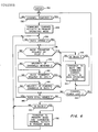
- the flow chart illustrating Fig. 6 begins with an enter step 130 after which a step 132 is next executed in which a determination is made as to whether or not the particular channel in which the Transfer Mechanism is located is powered or not. If not, step 132 is continually executed and re-executed until a determination is made that the channel being controlled for transfer is powered. Once this determination is made, a step 134 is next executed in which channel activity is commenced in the primary operating mode. In other words, the primary memory 18 is utilized rather than the backup memory 24.
- a step 136 is next executed in which a determination is made as to whether or not BUCS is armed or not. If not, step 136 is continually re-executed until a determination is made that BUCS is in fact armed. Once this determination is made, a step 138 is next executed in which a determination is made as to whether a BUCS transfer request has been made by the pilot, i.e., whether the signal on line 50 of Fig. 5 is present or not. If not, a step 140 is next executed in which a determination is made as to whether or not a majority of the channels are severed or not, i.e., as to whether a majority of the signals on lines 54 are severed or not.
- a step 142 is next executed in which a determination is made as to whether or not a majority of the channels are severed or not, i.e., as to whether a majority of the signals on lines 54 are severed or not. If not, a step 142 is next excecuted in which a determination is made as to whether or not the CPU has made a BUCS transfer request, i.e., whether the signal on line 62 of Figs. 4 and 5 is present or not. If not, a step 144 is next executed in which a determination is made as to whether or not a majority of the presently powered channels are in BUCS or not.
- a step 146 is next executed in which a determination is made as to whether or not BUCS is still armed. If so, the steps 138, 140, 142, and 144 are re-executed over and over again until a determination is made by one of the steps 138, 140, 142, 144 that a transfer to BUCS is appropriate as indicated by next executing a step 148 or BUCS is no longer armed, in which case a step 150 is next executed to determine whether or not the channel is using the primary memory 18 or the backup memory 24.
- step 148 is executed to determine whether the channel is already in BUCS or not. If not, a step 152 is executed in which a transfer to BUCS is effected and channel activity is commenced in that mode. If the channel were already in BUCS then step 152 would be unnecessary and a step 154 is directly executed in which a determination is made as to whether or not power has been lost or not in the particular channel. If so, the next step executed would be step 132 in which the program waits until the channel is powered up again and activity is recommenced in the primary mode. If channel power was not lost, then step 146 would next be executed in which a determination is made as to whether or not BUCS is still armed.
- step 150 determines whether or not the channel is still in BUCS. If so, a step 156 is next executed in which a transfer to the primary mode is made and channel activity is commenced in that mode. If it were determined in step 150 that the channel is no longer in BUCS then a transfer would be made directly to step 136 instead of executing step 156. In any event, step 136 is next executed after either step 150 or step 156 to determine whether BUCS is armed or not.
Abstract
Description
- This invention relates to transfer methods and mechanisms for digital control computers and, more particularly, to methods and mechanisms for transferring between a primary program memory and a backup program memory.
- In recent years, the increasing capabilities of digital microprocessors have led to the realization of redundant high performance digital control computer systems, e.g., for avionic applications. These powerful and reliable systems can perform complex computation and control functions, as well as detect, isolate and reconfigure the system elements with a high degree of reliability in the presence of hardware failures. However, the increasing complexity of the software resident in the systems, has led to the demand for software reliability and fault tolerance. In particular, there has been a strong demand for protection from the so-called generic software failure or error. Redundant digital systems utilizing identical software in all channels are particularly vulnerable to this type of error. This arises if all channels perform the same erroneous activity which cannot be predicted and which can lead to system failure. Therefore, there is a basic need for techniques that can protect the digital control system from generic software failures.
- The protection mechanism against generic software failures may take on many forms. For example, analog electronic computers may be used as backups for the primary digital system. An alternate solution involves the use of "in situ" alternate software which is switched on in case of detected generic software failure. In this case, the alternate software package is responsible for preventing loss of control of the system. This approach is quite cost effective, as the alternate software shares the same channel hardware, except for the program memory.
- The alternate software, resident in a backup memory, can be engaged or disengaged by means of a transfer mechanism. Clearly, the reliability of the overall system in the presence of generic common mode software faults is dependent on the reliability and fault tolerance of the transfer mechanism. Therefore, the problem of protection from generic software failures is closely associated with the need for a reliable, independent, fault tolerant backup mode transfer mechanism for digital control computer systems.
- An object of the present invenion is to provide a transfer mechanism for transferring from primary program memory to an alternate or backup program memory which is independent of the channel's software. In other words, the transfer must occur via a hardware mechanism free of any software control.
- Another object of the present invention is to provide a transfer method and mechanism for transferring all channels to and from the backup mode with near simultaneity. It will be understood that this cannot be done by a central transfer controller because of the possibility of a common mode hardware failure.
- Another object of the present invention is to provide a transfer mechanism and method that provides clean, transient free transfers, i.e., the process of transfer between the primary and backup program memories must not create transients or leave incompleted routines or apparent failures behind which can lead to loss of the system after the transfer.
- Another object of the present invention is to provide a transfer mechanism and method for a redundant system in which unambiguous performance is provided in the presence of a power loss to a subset of channels. In other words, once a transfer has taken place, it should be permanent (until disengaged) for the control system as a whole in the presence of any power-off transients to a subset of channels that may follow.
- Another object of the present invention is to provide a transfer mechanism method responsive to the detected occurrances of the so-called generic software fault and/or the occurrance of direct user transfer requests.
- According to the present invention, the transfer method and mechanism, when activated, sends a non-maskable interrupt to all of the channel processor(s) when a majority of channels detect (by means of a sever request, a user request or any other mechanism) a generic software failure; each of the processors then sends an acknowledge signal in response to the non-maskable interrupt after concluding the machine cycle in which it is engaged at the time it receives the interrupt; the acknowledge signal, which is purely a hardware driven signal, is then used to transfer the signal processor's program memory from a primary program memory to a backup program memory.
- In further accord with the present invention, the transfer method and mechanism remembers the "system" state and returns the channel to the system state after each restoration of power to the channel. In this manner, the transfer method and mechanism provides a transient free transfer without loss of control (sever) by the system.
- The method and mechanism of the present invention utilizes the technique of providing a shadow or backup memory for the primary program memory. The program contained in the shadow backup memory will be different from the program in the primary memory in order to provide for protection against a generic software failure in the primary software. A key element of this approach is the use of a non-maskable interrupt which cannot be disabled by software. The transfer is clean and transient free. Once the system is transferred into backup mode it will remain in backup mode unless the operator, e.g., the pilot, disarms the backup system for a transient-free return to primary mode.
- These and other objects, features and advantages of the present invention will become more apparent in light of the detailed description of a best mode embodiment thereof, as illustrated in the accompanying drawing.
-
- Fig. 1 is an illustration of a redundant digital computer control system in which the present invention is embodied in each channel;
- Fig. 2 is a functional illustration of the inventive concept of the present invention;
- Fig. 3 is a timing diagram presented as an aid for understanding the implementation of the transfer mechanism illustrated in Fig. 2;
- Fig. 4 is an illustration of a hardware implementation of the BUCS Transfer Mechamism, according to the present invention, particularly showing the various input and output signals which may be associated with such a Transfer Mechanism;
- Fig. 5 is a simplified block diagram illustration of a hardware implementation of the Transfer Mechanism of Fig. 4; and
- Fig. 6 is a simplified flow chart illustration of the logical steps which would be accomplished by a signal processor implementation of the Transfer Mechanism of Fig. 4.
- Fig. 1 is an illustration of a redundant channel digital
computer control system 10 having several redundant channels employed for system reliability. - Each channel is illustrated generally as having three main components, i.e., input/output (I/O) 12, an I/
O Interface 14, and asignal processor 16, typically a microprocessor. Eachsignal processor 16 in each channel will normally interface with aprimary memory space 18 over data, control andaddress lines data lines 20 and data andaddress lines 22 in order to permit the substitution of abackup memory 24 in place of theprimary memory 18 in the presence of several conditions including a generic software fault in the primary program memory. In the backup mode, the address anddata lines 26 and data andaddress lines 22 are used in lieu of the address anddata lines Transfer Mechanism 26 is functionally shown within each channel in Fig. 1 as the means whereby the transfer is effected. - A Non-Maskable
Interrupt Generator 28 is shown in each channel for providing and receiving various signals over asignal line 30 between the BUCSTransfer Mechanism 26 and theSignal Processor 16. - Referring now to Fig. 2, a
channel interrupt controller 28 is shown responsive to several priority interrupt signals on aline 32 for providing the various interrupts to thesignal processor 16. These will include a Non-Maskable Interrupt request signal on aline 34 generated in response to the presence of a signal on aline 35 from a generic softwarefailure detector indicator 35a. The detector/indicator 35a may be part of the BUCSTransfer Mechanism 26. The signal on theline 35 will be sent either if a generic software failure is detected or if requested, as indicated by a request signal on aline 35b. A number of channel failure (sever) signals are provided on a line 35c, each indicative of the status of its respective channel. The signal online 34 will be sent to theprocessor 16 upon detection of, for example, a generic software failure, among other conditions. - The
signal processor 16 will have a machine cycle which can typically be dynamically varied, e.g., from one clock period to ten clock periods. A series of such machine cycles are shown in Fig. 3(a). In the case illustrated, an NMI request signal is transmitted to the signal processor, as illustrated in Fig. 3(b) by awaveform 36. If an immediate acknowledge is returned by thesignal processor 16 to theinterrupt controller 28 then the signal processor might be interrupted in the middle of the performance of some vital task such as addressing memory as shown in general by a machine cycle 38 in Fig. 3(a). It is essential for the proper operation of the BUCSTransfer Mechanism 26 of the present invention for the acknowledge signal to be sent only during a period of time in which theSignal Processor 16 is not disturbed in its normal read/write activity. Thus, Fig. 3(c) shows anacknowledge signal waveform 40 corresponding to an acknowledge signal on aline 42 in Fig. 2 as occurring only during a special period of time 41 during which the signal processor is guaranteed to have completed the previous machine cycle 38, so as to avoid interfering with the signal processor's normal read/write activity. Fig. 3(d) shows that the transfer to backup memory is also effected during the NMI ACK machine cycle 41 such that the next succeeding machine cycle 41a accesses the backup memory. A transition 41b indicates a transfer boundary between the signal processor's accessing primary as opposed to backup memory. The actual transfer is initiated by the acknowledge signal on theline 42. The acknowledge signal would normally be input to a state latch 42a which in turn provides a transfer signal on aline 42b to alink 44, which changes its position to that shown byphantom lines 46 in response thereto. - Referring back to Fig. 2, it will be observed that the
BUCS Transfer Mechanism 26 is only shown functionally so as to aid in understanding the invention. The mechanism is illustrated in Fig. 2 as a simple single pole double throw switch, which may be break before make, make before break, or any variation thereof. The function, of course, is to respond to the acknowledge signal online 42 without software intervention to provide a switchover of the signal processor's address/data lines 22 from connection to the primary memory alongline 20 to connection to the backup memory alonglines 26a. This is effected by changing the position of the "link" 44 from the position shown in Fig. 2 to asecond position 46 shown by phantom lines within themechanism 26, as mentioned above. Of course, this purely functional description is not an accurate description of the actual means by which this would be effected in reality. In a real circuit, the function of themechanism 26 shown in Fig. 2 would be accomplished simply by thesignal processor 16 chip selecting a different memory at the proper time, as taught herein. Thus, it will be understood that Fig. 2 is presented primarily as an aid for understanding the function of the BUCS transfer mechanism. - Referring now to Fig. 4, a
BUCS Transfer Mechanism 26 is shown in a way which better illustrates the signals input thereto and output therefrom and how the BUCS Transfer Mechanism interfaces with the signal processor. - A BUCS Arm signal on a
line 48 is provided from, for example, a pilot actuated switch indicating that the pilot wishes theBUCS Transfer Mechanism 26 to be enabled. In the absence of this signal being activiated, a transfer between primary and backup memories will never occur. - A BUCS Engage signal on a
line 50 is also provided, for example, from the pilot to the various channel to perform a transfer regardless of detection of a generic software fault. This signal is provided to the backup transfer mechanism for manual actuation whenever the pilot desires a transfer or perceives the presence of a generic software failure. - The
BUCS Transfer Mechanism 26 will also be responsive, in a quad channel system, to a group of four redundant channel power status signals 52 each indicative of the power status of one of the four redundant channels in the quad system. The Transfer Mechanism is designed to always commence channel activity in the primary operating mode upon restoration or power. One of the foursignal lines 52 will originate with and be identical to one of four PORstatus signal lines 70 to be described below. One of the status signals online 70 is merely routed back into the BUCS Transfer Mechanism via one of the signal lines 52. Abreak 52a in thesignal line 52 is shown from its origination onsignal output line 70 in order to indicate that the routing back of the POR status signal to the input may be rather circuitous and may involve routing outside of the channel and also may involve signal conditioning not shown. - The
BUCS Transfer Mechanism 26 is also responsive to a group of four sever status signals on aline 54 each indicative of the sever status of one of the four channels in the quad system, including its own channel. If it is determined that a majority of channels are presently severed then a transfer to the BUCS mode will be made, if the channel were operating in the primary mode at the time. - The
BUCS Transfer Mechanism 26 is also responsive to a group of four signals on aline 56 each indicative of the mode status of one of the channels in the quad system. If it is determined that a majority of powered channels, as determined by reference to the signals online 52, are presently in the BUCS mode a channel will be transferred to the BUCS mode if it is presently still in the primary memory mode. It will be observed that one of the mode status signals originates at an output of the BUCS Transfer Mechanism, at asignal line 72, in a manner similar to that already described in connection with one of the signal lines 52. The same comments apply here. - It will also be observed that the plurality of input signals input on
input line 54 do not have one of that plurality of signals originating at the output, as with one of the signals in each of the cases corresponding to inputsignal lines BUCS Transfer Mechanism 26 could also include the necessary circuitry for originating these signals. However, in the embodiment shown in Fig. 4, they have been located elsewhere (not shown). Thus, it will be understood that although the circuitry for originating the signals onlines BUCS Transfer Mechanism 26 of Fig. 4, they could just as easily be provided elsewhere and not shown in the same manner that the source ofsignals 54 has not been shown in Fig. 4. These entities are freely transferable in and out of the BUCS Transfer Mechanism and are not an essential part of the present invention. - The
BUCS Transfer Mechanism 26 is also responsive to a power-on-reset (POR) signal on aline 58 for indicating that the channel has just been powered up and that the channel should commence activity in the primary operating mode. Hence, theBUCS Transfer Mechanism 26 will ensure that thePrimary Memory 18 will be utilized immediately after receiving a POR signal. - The
signal processor 16 provides a CPU commanded transfer signal on aline 62 to the transfer mechanism. The function of the signal online 62 is to provide a CPU initiated transfer vehicle controlled by software. A sever detect enable signal on aline 64 is also provided for the purpose of disabling transfer to BUCS after system POR, i.e., to allow initial system operating in primary mode. A signal on aline 65 allows for a second attempt to unsever. - A Non-Maskable Interrupt request signal on a
line 66 is provided to the signal processor from the BUCS Transfer Mechanism. The function of this signal is similar to that of the signal online 34 of Fig. 2 except that it is provided, in Fig. 4, from the BUCS Transfer Mechanism itself rather than from an interruptcontroller 28, as in Fig. 2. Functionally, there is no difference. Thesignal processor 16 sends an acknowledge on aline 68 at the proper moment so as not to interfere with its read/write operations with memory. - A group of four POR status signals on a
line 70 are provided, one to each of the channels, including one to itself (see signal line 56), for the purpose of indicating the POR status of this particular channel to each of the other channels. - A group of four channel mode status signals on a
line 72 each indicative of the mode status of the particular channel associated with the particular BUCS Transfer Mechanism from which they emerge are also provided to all the channels in the sytem (one of these signals appears on line 56). - A BUCS Engage lamp signal is provided on a
line 74 for energizing an indicator lamp indicative of whether the backup memory is being utilized at a particular poit in time or not. - A BUCS Armed lamp signal on a
line 76 is provided for energizing a lamp indicative of whether the pilot has armed BUCS. - An Unsever Arm latch signal on a
line 78 is provided to rearm an unsever mechanism (not shown) for the purpose of restoring a severed channel's ability to unsever its outputs and commence operation in a new mode. A mode status signal is provided on aline 79 to the signal processor. This signal determines which of two chip select signals is active. Depending on which chip select signal is active, one or the other of theprimary memory 18 or thebackup memory 24 will be selected. Thus, the signal online 79 may be thought of as the ultimate output signal of theBUCS Transfer Mechanism 26. - Fig. 5 is an illustration of one embodiment of the internals of a BUCS Transfer Mechanism. It will be noted that the embodiment shown in Fig. 5 is a hardware embodiment. However, it will be understood by those skilled in the art, that an embodiment using a signal processor and a program memory designed, for example, in accordance with the flow chart of Fig. 6, could substitute as well. However, it will be understood that such a program must be independent of both the primary and secondary modes. Hence, the software can't share processing functions or memory functions with either the primary or secondary. For this reasons BUCS is usually more reliable and cost effective as a hardware embodiment. Therefore, Fig. 6 will primarily be useful as an aid to understanding and for illustrating one set of logical steps which might be carried out in implementing the present invention.
- In Fig. 5, all of the input signals and output signals shown in Fig. 4 are illustrated. A BUCS Arm signal on
line 48 is provided to a BackupArm Conditioning Circuit 80 which conditions the signal to a level compatible with the input of anOR gate 84 which is responsive to the conditional Backup Arm signal online 82 and to the POR signal online 58. In the presence of either of these two asynchronous signals, the OR gate provides a signal on aline 86 to the RS input of a D flip-flop with asynchronous priority over the synchronous inputs. The flip-flop Q output will be high in the presence of a high input signal on a line 90 (preceded by a clock signal on a line 92) but will be overridden to produce a low at the Q output in the presence of a high signal on theline 86. This is to produce a non-maskable interrupt in the absence of the BUCS mechanism being armed or in the presence of POR. - A Channel Sever
Detector Majority Voter 94 is responsive to a clock signal on a line 95 and to the plurality of channel sever status signals 54 and provides an output signal on aline 96 to an ANDgate 98 in the presence of three or more i.e., majority of the foursignals 54 for a quad channel system indicating a sever condition. The ANDgate 98 is also responsive to a Sever Detect Enable signal on theline 64 from theprocessor 16 of Fig. 4. Both the signal on theline 96 and the signal on theline 64 must be present before the ANDgate 98 will provide an output signal on aline 100 to an OR gate 102. - The plurality of signals indicated by the
line 56 of Fig. 4 are provided to amajority voter 104 which provides an output signal on aline 106 to the OR gate 102 if three or more of the channel mode status signals indicate that three or more i.e., majority of channels in a quad channel system are in the BUCS mode. In that case, it would be required for the channel in questio nto also be in the BUCS mode and the signal online 106 is provided to the OR gate 102 for that purpose, as will be described in more detail below. - The BUCS Engage signal on the
line 50 is provided in response to the pilot actuating aswitch 108 in the cockpit. A PilotRequet signal conditioner 110 is responsive to the Engage Signal online 50 and provides a conditioned output signal on aline 112 which is conditioned to be compatible with the OR gate 102, e.g., a signal scaling from a high voltage of 12 VDC to a TTL compatible voltage of 5 VDC. - The OR gate 102 is also responsive to the CPU generated Transfer Command signal on
line 62. This signal permits a path for letting the channel join the system or unilaterally making the transfer in case of a generic software failure, as described above. - The D flip-
flop 88 provides the Non-Maskable Interrupt signal on theline 66 to theprocessor 16 of Fig. 4 in the presence of either a majority of the channels in sever, a majority of the channels in BUCS, a pilot request, or a CPU transfer command. Of course, the backup system must be armed before any of these conditions will actually result in a transfer to backup memory, as controlled at the RS input. - Once the Non-Maskable Interrupt signal on the
line 66 has been sent to the signal processor, the processor will respond with an NMI Acknowledge signal on theline 68 which is provided, along with the NMI signal itself, to an ANDgate 114 which will provide an output signal aline 116 to another D flip-flop 118 only if both the NMI and NMI Acknowledge signals are both present. The ensures that the processor has finished with its present activity before the backup memory is selected. - The D flip-
flop 118 will provide an output signal on aline 120 to aSignal Buffer Module 122 which is also responsive to a number of signals including the backup arm signal online 82, the POR signal online 58, the pilot request signal online 112, and the second unsever attempt signal online 65. - The
Signal Buffer Module 122 provides the unsever arm latch signal online 78, the BUCS armed lamp signal online 76, the BUCS engage lamp signal online 74, the channel mode status signals online 72, the POR status signals online 70 and, most importantly, the chip select switch signal online 79. - Although the BUCS Transfer Mechanism of Fig. 4 has been shown in a particular hardware embodiment in Fig. 5, it will be realized that many other hardware embodiments similar to that shown in Fig. 5 are very easily implemented. Such implementations would include various gate arrays and discrete component implementations. It will also be possible to implement the
Transfer Mechanism 26 by means of a separate signal processor using a set of instructions similar to those shown in Fig. 6 as long as it is not shared by either the primary or backup software programs resident inmemory spaces - Thus, the
BUCS Transfer Mechanism 26 of Fig. 4 will, for the purposes of Fig. 6, actually be a signal processor including all of the necessary internal components for such a processor including a CPU, a ROM for holding the program steps illustrated in Fig. 6 in permanent memory, a RAM, a data bus, a control bus, an address bus, and all of the other necessary components of a signal processor. - The flow chart illustrating Fig. 6 begins with an
enter step 130 after which astep 132 is next executed in which a determination is made as to whether or not the particular channel in which the Transfer Mechanism is located is powered or not. If not, step 132 is continually executed and re-executed until a determination is made that the channel being controlled for transfer is powered. Once this determination is made, astep 134 is next executed in which channel activity is commenced in the primary operating mode. In other words, theprimary memory 18 is utilized rather than thebackup memory 24. - A
step 136 is next executed in which a determination is made as to whether or not BUCS is armed or not. If not, step 136 is continually re-executed until a determination is made that BUCS is in fact armed. Once this determination is made, astep 138 is next executed in which a determination is made as to whether a BUCS transfer request has been made by the pilot, i.e., whether the signal online 50 of Fig. 5 is present or not. If not, astep 140 is next executed in which a determination is made as to whether or not a majority of the channels are severed or not, i.e., as to whether a majority of the signals onlines 54 are severed or not. If not, astep 142 is next executed in which a determination is made as to whether or not a majority of the channels are severed or not, i.e., as to whether a majority of the signals onlines 54 are severed or not. If not, astep 142 is next excecuted in which a determination is made as to whether or not the CPU has made a BUCS transfer request, i.e., whether the signal online 62 of Figs. 4 and 5 is present or not. If not, astep 144 is next executed in which a determination is made as to whether or not a majority of the presently powered channels are in BUCS or not. If not, astep 146 is next executed in which a determination is made as to whether or not BUCS is still armed. If so, thesteps steps step 148 or BUCS is no longer armed, in which case astep 150 is next executed to determine whether or not the channel is using theprimary memory 18 or thebackup memory 24. - If a determination is made by one of the steps 138-144 that a transfer to BUCS is appropriate, then step 148 is executed to determine whether the channel is already in BUCS or not. If not, a
step 152 is executed in which a transfer to BUCS is effected and channel activity is commenced in that mode. If the channel were already in BUCS then step 152 would be unnecessary and astep 154 is directly executed in which a determination is made as to whether or not power has been lost or not in the particular channel. If so, the next step executed would be step 132 in which the program waits until the channel is powered up again and activity is recommenced in the primary mode. If channel power was not lost, then step 146 would next be executed in which a determination is made as to whether or not BUCS is still armed. - If BUCS is not still armed, then a determination is made in
step 150 as to whether or not the channel is still in BUCS. If so, astep 156 is next executed in which a transfer to the primary mode is made and channel activity is commenced in that mode. If it were determined instep 150 that the channel is no longer in BUCS then a transfer would be made directly to step 136 instead of executingstep 156. In any event,step 136 is next executed after either step 150 or step 156 to determine whether BUCS is armed or not. - The program continues in the above described manner indefinitely and transfers may be made in and out of BUCS as indicated.
- Although the invention has been shown and described with respect to a best mode embodiment thereof, it should be understood by those skilled in the art that the foregoing and various other changes, omissions, and additions in the form and detail thereof may be made therein without departing from the spirit and scope of the invention.
Claims (7)
providing an interrupt signal to a signal processor, said interrupt signal being provided in response to the presence of a transfer request signal; and
providing a transfer signal in response to said interrupt signal after said signal processor concludes the machine cycle in which it is engaged at the time it receives said interrupt signal for initiating transfer of the signal processor's program memory from a primary program memory to a backup program memory.
means for providing an interrupt signal to an interrupt port of a signal processor, said port being associated with an uninterruptable interrupt function, said interrupt signal being provided in response to the presence of a transfer request signal; and
means for providing a transfer signal in response to said interrupt signal after concluding the machine cycle in which the signal processor is engaged at the time it receives said interrupt signal, said transfer signal for initiating transfer of the signal processor's program memory from a primary program memory to a backup program memory.
testing for the presence of signals indicative of incorrect operation in one or more of the channels;
providing an interrupt signal, in the presence of a majority of the channels providing signals indicative of incorrect operation;
permitting the signal processor to complete its present operation in response to said interrupt signal and then suspending further signal processing steps until the completion of a transfer from the primary memory to the alternate memory;
providing a suspend acknowledge signal in the presence of the signal processor suspending the execution of further steps;
disconnecting the signal processor from the primary memory in response to said suspend acknowledge signal; and
connecting the signal processor to the alternate memory.
Applications Claiming Priority (2)
| Application Number | Priority Date | Filing Date | Title |
|---|---|---|---|
| US92261786A | 1986-10-24 | 1986-10-24 | |
| US922617 | 1986-10-24 |
Publications (3)
| Publication Number | Publication Date |
|---|---|
| EP0265366A2 true EP0265366A2 (en) | 1988-04-27 |
| EP0265366A3 EP0265366A3 (en) | 1990-05-16 |
| EP0265366B1 EP0265366B1 (en) | 1995-06-28 |
Family
ID=25447332
Family Applications (1)
| Application Number | Title | Priority Date | Filing Date |
|---|---|---|---|
| EP19870630204 Expired - Lifetime EP0265366B1 (en) | 1986-10-24 | 1987-10-15 | An independent backup mode transfer method and mechanism for digital control computers |
Country Status (3)
| Country | Link |
|---|---|
| EP (1) | EP0265366B1 (en) |
| JP (1) | JPS63113701A (en) |
| DE (1) | DE3751374T2 (en) |
Cited By (2)
| Publication number | Priority date | Publication date | Assignee | Title |
|---|---|---|---|---|
| WO2001022220A1 (en) | 1999-09-22 | 2001-03-29 | Saab Ab | A computer device with a safety function |
| US7120772B2 (en) * | 2003-02-26 | 2006-10-10 | Cheertek Incorporation | Micro-system for burn-in system program from a plug-able subsystem into main memory and method thereof |
Families Citing this family (3)
| Publication number | Priority date | Publication date | Assignee | Title |
|---|---|---|---|---|
| JPH02297601A (en) * | 1989-05-11 | 1990-12-10 | Sanyo Electric Co Ltd | Electric apparatus such as washing machine or the like |
| JPH03131902A (en) * | 1989-10-18 | 1991-06-05 | Mitsubishi Electric Corp | Industrial control device |
| WO2003104616A1 (en) * | 2002-06-07 | 2003-12-18 | 三菱重工業株式会社 | Turbine bucket assembly and its assembling method |
Citations (4)
| Publication number | Priority date | Publication date | Assignee | Title |
|---|---|---|---|---|
| JPS56166000A (en) * | 1980-05-27 | 1981-12-19 | Mitsubishi Electric Corp | Duplicated memory |
| US4358823A (en) * | 1977-03-25 | 1982-11-09 | Trw, Inc. | Double redundant processor |
| EP0186965A1 (en) * | 1984-11-27 | 1986-07-09 | Honeywell Inc. | Digital fail operational automatic flight control system utilising redundant dissimilar data processing |
| GB2172722A (en) * | 1985-03-22 | 1986-09-24 | United Technologies Corp | Backup control system (bucs) |
-
1987
- 1987-10-15 EP EP19870630204 patent/EP0265366B1/en not_active Expired - Lifetime
- 1987-10-15 DE DE19873751374 patent/DE3751374T2/en not_active Expired - Fee Related
- 1987-10-19 JP JP26364087A patent/JPS63113701A/en active Pending
Patent Citations (4)
| Publication number | Priority date | Publication date | Assignee | Title |
|---|---|---|---|---|
| US4358823A (en) * | 1977-03-25 | 1982-11-09 | Trw, Inc. | Double redundant processor |
| JPS56166000A (en) * | 1980-05-27 | 1981-12-19 | Mitsubishi Electric Corp | Duplicated memory |
| EP0186965A1 (en) * | 1984-11-27 | 1986-07-09 | Honeywell Inc. | Digital fail operational automatic flight control system utilising redundant dissimilar data processing |
| GB2172722A (en) * | 1985-03-22 | 1986-09-24 | United Technologies Corp | Backup control system (bucs) |
Non-Patent Citations (3)
| Title |
|---|
| PATENT ABSTRACTS OF JAPAN, vol. 6, no. 51 (P-108)[929], 6th April 1982; & JP-A-56 166 000 (MITSUBISHI) 19-12-1981 * |
| PROCEEDINGS OF THE 7th IEEE/AIAA DIGITAL AVIONICS SYSTEMS CONFERENCE, 13th-16th October 1986, Fort Worth, Texas, US, pages 523-528; E.F. HITT: "Real-time fault tolerant software in distributed avionics systems architectures using digital data buses" * |
| REVIEW OF THE ELELCTRICAL COMMUNICATION LABORATORIES, vol. 33, no. 4, 1985, pages 697-705; K. UCHIYAMA et al.: "System reliability Techniques in the DIPS-106 Network OS" * |
Cited By (3)
| Publication number | Priority date | Publication date | Assignee | Title |
|---|---|---|---|---|
| WO2001022220A1 (en) | 1999-09-22 | 2001-03-29 | Saab Ab | A computer device with a safety function |
| US6959402B1 (en) | 1999-09-22 | 2005-10-25 | Saab Ab | Computer device with a safety function |
| US7120772B2 (en) * | 2003-02-26 | 2006-10-10 | Cheertek Incorporation | Micro-system for burn-in system program from a plug-able subsystem into main memory and method thereof |
Also Published As
| Publication number | Publication date |
|---|---|
| DE3751374T2 (en) | 1995-11-09 |
| DE3751374D1 (en) | 1995-08-03 |
| JPS63113701A (en) | 1988-05-18 |
| EP0265366B1 (en) | 1995-06-28 |
| EP0265366A3 (en) | 1990-05-16 |
Similar Documents
| Publication | Publication Date | Title |
|---|---|---|
| CA1259415A (en) | High level self-checking intelligent i/o controller | |
| US4757442A (en) | Re-synchronization system using common memory bus to transfer restart data from non-faulty processor to failed processor | |
| EP0088789B1 (en) | Multiprocessor computer system | |
| CA1255008A (en) | Virtual command rollback in a fault tolerant data processing system | |
| CN107347018B (en) | Three-redundancy 1553B bus dynamic switching method | |
| US4937741A (en) | Synchronization of fault-tolerant parallel processing systems | |
| JP5337022B2 (en) | Error filtering in fault-tolerant computing systems | |
| EP0441087A1 (en) | Checkpointing mechanism for fault-tolerant systems | |
| EP2153328B1 (en) | Data processing system, data processing method, and apparatus | |
| US5128943A (en) | Independent backup mode transfer and mechanism for digital control computers | |
| US7020800B2 (en) | System and method for memory failure recovery using lockstep processes | |
| JPH0812621B2 (en) | Information transfer method and device | |
| CA2339783A1 (en) | Fault tolerant computer system | |
| US5163138A (en) | Protocol for read write transfers via switching logic by transmitting and retransmitting an address | |
| CA2530913A1 (en) | Fault tolerant computer system and interrupt control method for the same | |
| EP0415546A2 (en) | Memory device | |
| US4486834A (en) | Multi-computer system having dual common memory | |
| US3833798A (en) | Data processing systems having multiplexed system units | |
| JPS59106056A (en) | Failsafe type data processing system | |
| EP0265366A2 (en) | An independent backup mode transfer method and mechanism for digital control computers | |
| JP2006512634A (en) | Method and circuit arrangement for synchronizing processing units synchronously or asynchronously clocked | |
| CA2002966C (en) | Method of checking test program in duplex processing apparatus | |
| EP0416732B1 (en) | Targeted resets in a data processor | |
| CA2498656A1 (en) | Method for synchronizing events, particularly for processors of fault-tolerant systems | |
| JPS5917467B2 (en) | Control computer backup method |
Legal Events
| Date | Code | Title | Description |
|---|---|---|---|
| PUAI | Public reference made under article 153(3) epc to a published international application that has entered the european phase |
Free format text: ORIGINAL CODE: 0009012 |
|
| AK | Designated contracting states |
Kind code of ref document: A2 Designated state(s): DE FR GB IT |
|
| PUAL | Search report despatched |
Free format text: ORIGINAL CODE: 0009013 |
|
| AK | Designated contracting states |
Kind code of ref document: A3 Designated state(s): DE FR GB IT |
|
| 17P | Request for examination filed |
Effective date: 19901024 |
|
| 17Q | First examination report despatched |
Effective date: 19921125 |
|
| GRAA | (expected) grant |
Free format text: ORIGINAL CODE: 0009210 |
|
| AK | Designated contracting states |
Kind code of ref document: B1 Designated state(s): DE FR GB IT |
|
| ET | Fr: translation filed | ||
| REF | Corresponds to: |
Ref document number: 3751374 Country of ref document: DE Date of ref document: 19950803 |
|
| ITF | It: translation for a ep patent filed |
Owner name: UFFICIO BREVETTI RICCARDI & C. |
|
| PLBE | No opposition filed within time limit |
Free format text: ORIGINAL CODE: 0009261 |
|
| STAA | Information on the status of an ep patent application or granted ep patent |
Free format text: STATUS: NO OPPOSITION FILED WITHIN TIME LIMIT |
|
| 26N | No opposition filed | ||
| PGFP | Annual fee paid to national office [announced via postgrant information from national office to epo] |
Ref country code: FR Payment date: 20001009 Year of fee payment: 14 |
|
| PGFP | Annual fee paid to national office [announced via postgrant information from national office to epo] |
Ref country code: GB Payment date: 20001017 Year of fee payment: 14 |
|
| PGFP | Annual fee paid to national office [announced via postgrant information from national office to epo] |
Ref country code: DE Payment date: 20001020 Year of fee payment: 14 |
|
| PG25 | Lapsed in a contracting state [announced via postgrant information from national office to epo] |
Ref country code: GB Free format text: LAPSE BECAUSE OF NON-PAYMENT OF DUE FEES Effective date: 20011015 |
|
| REG | Reference to a national code |
Ref country code: GB Ref legal event code: IF02 |
|
| GBPC | Gb: european patent ceased through non-payment of renewal fee |
Effective date: 20011015 |
|
| PG25 | Lapsed in a contracting state [announced via postgrant information from national office to epo] |
Ref country code: FR Free format text: LAPSE BECAUSE OF NON-PAYMENT OF DUE FEES Effective date: 20020628 |
|
| PG25 | Lapsed in a contracting state [announced via postgrant information from national office to epo] |
Ref country code: DE Free format text: LAPSE BECAUSE OF NON-PAYMENT OF DUE FEES Effective date: 20020702 |
|
| REG | Reference to a national code |
Ref country code: FR Ref legal event code: ST |
|
| PG25 | Lapsed in a contracting state [announced via postgrant information from national office to epo] |
Ref country code: IT Free format text: LAPSE BECAUSE OF NON-PAYMENT OF DUE FEES;WARNING: LAPSES OF ITALIAN PATENTS WITH EFFECTIVE DATE BEFORE 2007 MAY HAVE OCCURRED AT ANY TIME BEFORE 2007. THE CORRECT EFFECTIVE DATE MAY BE DIFFERENT FROM THE ONE RECORDED. Effective date: 20051015 |