EP0265096B1 - Unheading device and method for coking drums - Google Patents
Unheading device and method for coking drums Download PDFInfo
- Publication number
- EP0265096B1 EP0265096B1 EP87308664A EP87308664A EP0265096B1 EP 0265096 B1 EP0265096 B1 EP 0265096B1 EP 87308664 A EP87308664 A EP 87308664A EP 87308664 A EP87308664 A EP 87308664A EP 0265096 B1 EP0265096 B1 EP 0265096B1
- Authority
- EP
- European Patent Office
- Prior art keywords
- head unit
- drum
- coking drum
- flange
- plate
- Prior art date
- Legal status (The legal status is an assumption and is not a legal conclusion. Google has not performed a legal analysis and makes no representation as to the accuracy of the status listed.)
- Expired - Lifetime
Links
Images


Classifications
-
- C—CHEMISTRY; METALLURGY
- C10—PETROLEUM, GAS OR COKE INDUSTRIES; TECHNICAL GASES CONTAINING CARBON MONOXIDE; FUELS; LUBRICANTS; PEAT
- C10B—DESTRUCTIVE DISTILLATION OF CARBONACEOUS MATERIALS FOR PRODUCTION OF GAS, COKE, TAR, OR SIMILAR MATERIALS
- C10B33/00—Discharging devices; Coke guides
-
- C—CHEMISTRY; METALLURGY
- C10—PETROLEUM, GAS OR COKE INDUSTRIES; TECHNICAL GASES CONTAINING CARBON MONOXIDE; FUELS; LUBRICANTS; PEAT
- C10B—DESTRUCTIVE DISTILLATION OF CARBONACEOUS MATERIALS FOR PRODUCTION OF GAS, COKE, TAR, OR SIMILAR MATERIALS
- C10B25/00—Doors or closures for coke ovens
- C10B25/02—Doors; Door frames
- C10B25/08—Closing and opening the doors
- C10B25/10—Closing and opening the doors for ovens with vertical chambers
-
- Y—GENERAL TAGGING OF NEW TECHNOLOGICAL DEVELOPMENTS; GENERAL TAGGING OF CROSS-SECTIONAL TECHNOLOGIES SPANNING OVER SEVERAL SECTIONS OF THE IPC; TECHNICAL SUBJECTS COVERED BY FORMER USPC CROSS-REFERENCE ART COLLECTIONS [XRACs] AND DIGESTS
- Y10—TECHNICAL SUBJECTS COVERED BY FORMER USPC
- Y10T—TECHNICAL SUBJECTS COVERED BY FORMER US CLASSIFICATION
- Y10T29/00—Metal working
- Y10T29/49—Method of mechanical manufacture
- Y10T29/49718—Repairing
- Y10T29/49721—Repairing with disassembling
- Y10T29/4973—Replacing of defective part
Definitions
- This invention pertains to an unheading device for coking drums which is capable of remote operation. It pertains particularly to such an unheading device for removing and replacing a lower head unit for delayed coking drums and to a method for remote operation of the unheading device.
- the resulting coke is deposited on the inner walls of the drum and must be periodically removed, usually at 36-48 hour intervals.
- Such coke removal is accomplished through an opening in the lower end of the vertically-oriented drum, and is presently accomplished by manually removing a lower head unit and installing a chute to direct the coke removed to a desired location, such as to a hopper or rail car.
- the coker drum operates at relatively high temperatures of 260-482°C (500-900°F)
- removal of the hot coker drum lower head by manual means is slow and somewhat hazardous and is therefore undesirable.
- the present invention advantageously provides a novel unheading device for remote safe removal and replacement of coke drum lower head units and thereby provides for more rapid removal of coke from the drum during decoking operations.
- the present invention is directed at apparatus for the removal and replacement of the lower head unit of a coking drum, the head unit having an upper flange removably attached to a lower flange of the drum.
- Apparatus according to the invention comprises a plurality of clamping devices pivotally attached to the coking drum lower frange and having bolts for holding the head unit flange to the coking drum flange means equally spaced around the perimeter of the head unit for detensioning the bolts, and means for pivotally removing detensioned bolts from their holding position to disconnect the head unit from the coking drum; a platform device having a support plate movable vertically to lower the head unit from the coking drum and movable laterally therefrom, the plate including brackets for holding the coking drum thereon; means for tilting the plate through an angle of 20° to 60° with the horizontal plane when laterally spaced from the drum to tip the head unit thereon for cleaning; a coke chute attached to the platform device and coupled to the tilting means, to move into engagement with
- the fasteners are swung radially outwardly and upwardly by vertically-oriented piston actuators attached to the vessel and thus permit lowering the head unit.
- the preferred platform device includes upper and lower plates having dual lift lever linkages provided therebetween, and is operated by dual hydraulic piston actuators attached to the upper and lower plates of the platform.
- the chute can be attached to the platform upper plate. After unfastening the head unit mating flanges, the platform device lowers the head unit by operation of the piston actuator and moves it laterally from beneath the drum by another piston actuator which can extend through a lower portion of the head unit. The platform movement also raises the chute into contact with the coking drum lower flange for a suitable position for cleaning by action of the vertical piston located between the upper and lower plates of the platform.
- the platform is adapted to lower the coke chute and then move the head unit laterally to a position back under the drum lower flange, then raise the head unit into mating position for rebolting to the drum lower flange.
- the bolt detensioning and lift mechanisms for the head and coke chute can be advantageously operated by hydraulic pistons operated by remote control. This lift and chute arrangement can be advantageously used for either new or existing delayed coking drums to decoke the drums much more rapidly and with increased safety at intervals of 36-48 hours.
- the invention also provides a method of removing and replacing the lower head unit of a coking drum attached to a lower flange thereof, using apparatus as described above.
- the method comprises the steps of:
- the present invention enables a coker drum lower head unit to be conveniently removed from the coker drum using a remotely operated unheading device, which loosens the plurality of bolt fasteners and pivots the fasteners outwardly, then lowers the head unit and moves it laterally aside.
- the apparatus and method of the invention permit more rapid and safe removal of coke deposited in a coking drum, so as to increase the available operating time for the drum, and also improves personal safety by avoiding undesirable exposure of personnel to hot hydrocarbons, steam and water during such unheading operations.
- a delayed coking drum or vessel 10 is vertically-oriented and supported by an adjacent frame structure 11 and also supported by a platform structure 12 provided below the drum 10.
- Such delayed coking drums 10 for use in petroleum refineries are usually 6-8 m (20-26 ft.) diameter and 24.4-30.5 m (80-100ft.) tall, and have a tapered lower portion 10a attached to a lower flange 13 which is usually 5-7 ft. diameter.
- a removable head unit 14 is pressure-tightly attached to flange 13 by a plurality of clamp fastener means 20.
- the coke deposited in coking drum vessel 10 is removed from the drum periodically as needed by removing the head unit 14 and cutting the coke from within the vessel, so that the coke falls through a chute 16 into a storage pit, pad or rail car (not shown).
- head unit 14 which is fastened onto lower flange 13 by pivotable multiple clamp fastener means 20, is shown in greater detail by Fig. 2. It will be noted that head unit 14 includes a lateral conduit 18 used for feeding hydrocarbon, steam and water materials into the coker vessel 10. Conduit 18 is also used to drain water from the drum 10. As is shown in Fig. 2 and further shown in Fig. 3,16-48 swing type fasteners 20 are provided evenly spaced around the periphery of flange 13 for clamping upper flange 15 of the head unit 14 onto flange 13 of vessel 10.
- each clamping device 20 is constructed and operated similarly, and includes a clamp arm 21 which is pivotably attached at its upper end 21a to flange 13 by a pivot pin 22 pivotably secured to the upper surface of flange 13 at near the outer perimeter of the flange.
- the other or lower end 21b of clamp arm 21 is pivotally attached to a lower end of a piston actuator 24, and the upper end of actuator 24 is pivotably attached at 25 to the outer wall of coker drum 10.
- the lower end 21b of each clamp 21 is also rigidly connected via pivot pin 22 to the upper end of a bolt 26, which is provided in a vertical slot 27 provided in both the lower flange 13 of vessel 10 and in the mating upper flange 15 of the head unit 14.
- a remotely operated tensioning unit 28 is provided attached to each bolt 26 below flange 15.
- the bolt tensioning device 28 may be similar to that described in U.S. Patent 3,015,975 to Biach, which is incorporated herein by reference to the extent necessary to adequately disclose the present invention.
- the tensioning units 28 are usually operated by a suitable hydraulic pressure source.
- the bolt tensioning units 28 are first remotely actuated to detension the bolts 26 thereby lowering the head unit 14 by a distance of 0,6-2,5 cm (0.25-1 inch) onto top plate 31 of a lift platform support device 30.
- the swing actuator pistons 24 are contracted so as to swing the bolts 26 outwardly and upwardly to a disconnected or unfastened position as shown in Fig. 9.
- lift platform support device 30 is provided below head unit 14, as is shown in Figs. 2, 4 and 5.
- the platform device 30 is adapted for contacting the lower support plate 17 of head unit 14, as additionally shown by Figs. 9 and 10.
- PLatform device 30 includes upper plate 31 and pivoted lifting levers 32 and 33 pivotably and slidably attached to upper plate 31 and to lower plate 34.
- Fig. 10 shows an enlarged view of head unit 14, which shows upper support plate 31 in position in contact with lower plate 17 of head unit 14.
- the upper plate 31 of the platform device 30 is raised to be in within 0,6-2,5 cm (0.25-1 inch) of contact with plate 17 by action of the linkage members 32 and 33, which are slidably attached at their lower ends to plate 34.
- the head unit 14 is first lowered by 0,6-2,5 cm (0.25-1 inch) while detensioning bolts 26 using bolt tensioning devices 28 onto plate 31, and is then further lowered by action of platform device 30 linkage members 32 and 33, as shown in Figs. 11 and 12.
- head unit 14 Following such lowering of the head unit 14, it is then moved laterally to an offset position at one side as shown by Fig. 13 by retraction action of the piston actuator 36.
- the lower plate 17 of head unit 14 is retained by dual brackets 37a and 37b, which are fixed to tipped portion 31a of upper plate 31.
- head unit 14 is also tipper upwardly at an angle of preferably 30-50° to the horizontal plane at pivot 35 by action of piston 38, as is shown by Fig. 15.
- This tipped position of head unit 14 permits manually cleaning the head interior portion and also permits cleaning the conduit 18 attached thereto.
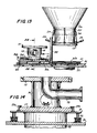
- chute 16 which is attached to untipped portion 31b of upper plate 31 of the platform device 30, is simultaneously raised by action of linkages 32, 33 and piston actuator 38 so that chute 16 contacts the lower flange 13 of the coker vessel 10.
- An enlarged partial view of the chute 16 being in contact with the lower flange 13 of the coker vessel 12 is shown by Fig. 16.
- the coke is removed from within drum 10 and falls through chute 16 to a storage pit or rail car (not shown).
- the head unit 14 is lowered and returned to its original position and reconnected onto the drum flange 13. This return movement is accomplished by first lowering platform 31 by actuator piston 38 then extending piston actuator 36 to move head unit 14 laterally to a position in vertical alignment below flange 13, then raising platform 31 so that head unit 14 is again placed against flange 13. Next, the swing actuators 24 are extended so as to pivot the bolts 26 downwardly into the slots 27. Then the multiple tensioning units 28 are actuated so as to clamp the mating flanges 13 and 15 tightly together again.
- coking drum used for delayed coking of petroleum feedstockes, after 36-48 hours of operation sufficient coke is deposited on the inner walls of the drum that removal of the coke is required before continued operation.
- the coking drum which is equipped with a lower head unit constructed and operated in accordance with this invention, is shut down, depressurized and the lower head unit is removed.
- Coker lower flange diameter 1.82m (72ins.) Head unit flange diameter, 1.82m (72ins.) Header length, 0.46m (18ins) Number of fastener swing bolts 36 Swing bolt diameter, 5cms (2ins) Bolt slot width, 6.25cms (2.5ins) Vertical movement of lift platform, 30.5cms (12ins) Lateral movement of head unit, 2.13m (84ins) Lift actuator hydraulic pressure, 10.34.106 N/m2 (1500psig)
Landscapes
- Chemical & Material Sciences (AREA)
- Engineering & Computer Science (AREA)
- Materials Engineering (AREA)
- Oil, Petroleum & Natural Gas (AREA)
- Organic Chemistry (AREA)
- Coke Industry (AREA)
Description
- This invention pertains to an unheading device for coking drums which is capable of remote operation. It pertains particularly to such an unheading device for removing and replacing a lower head unit for delayed coking drums and to a method for remote operation of the unheading device.
- During the operation of delayed coking drums or units for coking of various hydrocarbon feedstreams in petroleum refinery operations, the resulting coke is deposited on the inner walls of the drum and must be periodically removed, usually at 36-48 hour intervals. Such coke removal is accomplished through an opening in the lower end of the vertically-oriented drum, and is presently accomplished by manually removing a lower head unit and installing a chute to direct the coke removed to a desired location, such as to a hopper or rail car. Because the coker drum operates at relatively high temperatures of 260-482°C (500-900°F), such removal of the hot coker drum lower head by manual means is slow and somewhat hazardous and is therefore undesirable. The present invention advantageously provides a novel unheading device for remote safe removal and replacement of coke drum lower head units and thereby provides for more rapid removal of coke from the drum during decoking operations.
- The present invention is directed at apparatus for the removal and replacement of the lower head unit of a coking drum, the head unit having an upper flange removably attached to a lower flange of the drum. Apparatus according to the invention comprises a plurality of clamping devices pivotally attached to the coking drum lower frange and having bolts for holding the head unit flange to the coking drum flange means equally spaced around the perimeter of the head unit for detensioning the bolts, and means for pivotally removing detensioned bolts from their holding position to disconnect the head unit from the coking drum; a platform device having a support plate movable vertically to lower the head unit from the coking drum and movable laterally therefrom, the plate including brackets for holding the coking drum thereon; means for tilting the plate through an angle of 20° to 60° with the horizontal plane when laterally spaced from the drum to tip the head unit thereon for cleaning; a coke chute attached to the platform device and coupled to the tilting means, to move into engagement with the coking drum lower flange as the plate tilts to provide for coke removal; and means for reversing the movement of the coke chute, the plate and the clamping devices to return the lower head unit to the coking drum and secure the flanges with the bolts. The apparatus provides for the head unit to be returned laterally so as to be in vertical alignment with the coking drum lower flange and then lifted up into engagement with the lower flange, after which the head unit fasteners are refastened into place.
- In preferred apparatus of the inventor, the fasteners are swung radially outwardly and upwardly by vertically-oriented piston actuators attached to the vessel and thus permit lowering the head unit. The preferred platform device includes upper and lower plates having dual lift lever linkages provided therebetween, and is operated by dual hydraulic piston actuators attached to the upper and lower plates of the platform. The chute can be attached to the platform upper plate. After unfastening the head unit mating flanges, the platform device lowers the head unit by operation of the piston actuator and moves it laterally from beneath the drum by another piston actuator which can extend through a lower portion of the head unit. The platform movement also raises the chute into contact with the coking drum lower flange for a suitable position for cleaning by action of the vertical piston located between the upper and lower plates of the platform.
- After decoking of the coke drum is completed, the platform is adapted to lower the coke chute and then move the head unit laterally to a position back under the drum lower flange, then raise the head unit into mating position for rebolting to the drum lower flange. The bolt detensioning and lift mechanisms for the head and coke chute can be advantageously operated by hydraulic pistons operated by remote control. This lift and chute arrangement can be advantageously used for either new or existing delayed coking drums to decoke the drums much more rapidly and with increased safety at intervals of 36-48 hours.
- The invention also provides a method of removing and replacing the lower head unit of a coking drum attached to a lower flange thereof, using apparatus as described above. The method comprises the steps of:
- a) detensioning the bolts of the clamping devices while supporting the lower head unit on the upper plate of the platform device;
- b) pivoting the bolts outwardly and upwardly from the head unit;
- c) lowering the head unit on the plate and moving it laterally relative to the coking drum;
- d) tilting the plate to tip the
head unit 20° to 60° and simultaneously raising a coke chute into engagement with the coking drum lower flange; - e) removing coke from the coking drum through the chute while cleaning the head unit in its tipped orientation; and
- f) after completion of step e) reversing steps a) to d) to refit the head unit to the coking drum.
- The present invention enables a coker drum lower head unit to be conveniently removed from the coker drum using a remotely operated unheading device, which loosens the plurality of bolt fasteners and pivots the fasteners outwardly, then lowers the head unit and moves it laterally aside. The apparatus and method of the invention permit more rapid and safe removal of coke deposited in a coking drum, so as to increase the available operating time for the drum, and also improves personal safety by avoiding undesirable exposure of personnel to hot hydrocarbons, steam and water during such unheading operations.
- A preferred embodiment of the invention will now be described with reference to the accompanying drawings, in which:
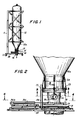
- Fig. 1 shows a vertically-oriented delayed coking drum with a removable lower head unit and platform support means provided at the drum lower end;
- Fig. 2 shows an enlarged elevation view of the coking drum head unit attached to the lower end of the drum by a plurality of fastener means and a lift platform device provided below the head unit;
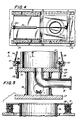
- Fig. 3 shows an enlarged cross-section view taken at line 3-3' of Fig. 2 and shows detensioning and actuator means for removing the multiple fasteners in the lower flange of the coker drum;
- Fig. 4 shows a plan view of the unheading device taken at line 4-4ʹ of Fig. 2;
- Fig. 5 shows a sectional elevation view taken through the head unit at line 5-5ʹ of Fig. 2, and also shows the coker head unit prior to its engagement by the head lift platform support;
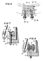
- Fig. 6 shows a detail plan view of one flange clamp fastening device taken at line 6-6ʹ of Fig. 5;
- Fig. 7 shows a sectional elevation view taken through the flange clamp fastener device at line 7-7ʹ of Fig. 6;
- Fig. 8 shows another sectional elevation view of the flange clamp fastener taken at line 8-8ʹ of Fig. 6;
- Fig. 9 shows an elevation view similar to Fig. 2, but after the lift platform device has contacted the head unit and the flange fastener clamps have been unlatched;
- Fig. 10 shows an enlarged sectional elevation view similar to Fig. 5 but after the lift platform device has contacted the coker head unit;
- Fig. 11 shows an elevation view similar to Fig. 9 but showing the coker head unit being lowered from the coker vessel;
- Fig. 12 shows an enlarged cross-sectional elevation view of the head unit ta ken at line 12-12ʹ of Fig. 11;
- Fig. 13 shows an elevation view of the coker head unit after being moved laterally away from the coker vessel lower flange;
- Fig. 14 shows an enlarged sectional elevation view of the head unit taken at line 14-14ʹ of Fig. 13;
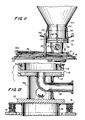
- Fig. 15 shows an elevational view of the head unit after being tipped for cleaning, and a chute connected to the coker drum lower flange for removal of the coke contained therein; and
- Fig. 16 shows an enlarged vertical sectional view of the coker flange and connected chute taken at line 16-16ʹ of Fig. 15.
- As generally shown in Fig. 1, a delayed coking drum or
vessel 10 is vertically-oriented and supported by anadjacent frame structure 11 and also supported by aplatform structure 12 provided below thedrum 10. Such delayed cokingdrums 10 for use in petroleum refineries are usually 6-8 m (20-26 ft.) diameter and 24.4-30.5 m (80-100ft.) tall, and have a taperedlower portion 10a attached to alower flange 13 which is usually 5-7 ft. diameter. Aremovable head unit 14 is pressure-tightly attached toflange 13 by a plurality of clamp fastener means 20. The coke deposited in cokingdrum vessel 10 is removed from the drum periodically as needed by removing thehead unit 14 and cutting the coke from within the vessel, so that the coke falls through achute 16 into a storage pit, pad or rail car (not shown). - The
head unit 14, which is fastened ontolower flange 13 by pivotable multiple clamp fastener means 20, is shown in greater detail by Fig. 2. It will be noted thathead unit 14 includes alateral conduit 18 used for feeding hydrocarbon, steam and water materials into thecoker vessel 10.Conduit 18 is also used to drain water from thedrum 10. As is shown in Fig. 2 and further shown in Fig. 3,16-48swing type fasteners 20 are provided evenly spaced around the periphery offlange 13 for clampingupper flange 15 of thehead unit 14 ontoflange 13 ofvessel 10. - As shown in greater detail by Figs. 5-8, each
clamping device 20 is constructed and operated similarly, and includes aclamp arm 21 which is pivotably attached at itsupper end 21a to flange 13 by apivot pin 22 pivotably secured to the upper surface offlange 13 at near the outer perimeter of the flange. The other orlower end 21b ofclamp arm 21 is pivotally attached to a lower end of apiston actuator 24, and the upper end ofactuator 24 is pivotably attached at 25 to the outer wall ofcoker drum 10. Thelower end 21b of eachclamp 21 is also rigidly connected viapivot pin 22 to the upper end of abolt 26, which is provided in avertical slot 27 provided in both thelower flange 13 ofvessel 10 and in the matingupper flange 15 of thehead unit 14. Also, a remotely operatedtensioning unit 28 is provided attached to eachbolt 26 belowflange 15. Thebolt tensioning device 28 may be similar to that described in U.S. Patent 3,015,975 to Biach, which is incorporated herein by reference to the extent necessary to adequately disclose the present invention. Thetensioning units 28 are usually operated by a suitable hydraulic pressure source. - When it is desired to open the joint between the
mating flanges bolt tensioning units 28 are first remotely actuated to detension thebolts 26 thereby lowering thehead unit 14 by a distance of 0,6-2,5 cm (0.25-1 inch) ontotop plate 31 of a liftplatform support device 30. The, theswing actuator pistons 24 are contracted so as to swing thebolts 26 outwardly and upwardly to a disconnected or unfastened position as shown in Fig. 9. - For supporting and removing the
head unit 14 from the coker vessellower flange 13, liftplatform support device 30 is provided belowhead unit 14, as is shown in Figs. 2, 4 and 5. Theplatform device 30 is adapted for contacting thelower support plate 17 ofhead unit 14, as additionally shown by Figs. 9 and 10.PLatform device 30 includesupper plate 31 andpivoted lifting levers upper plate 31 and tolower plate 34. After thefastener bolts 26 have been detensioned and the head unit initially lowered by 0,6-2,5 cm (0.25-1 inch) to provide agap 19 betweenflanges head unit 14 is is being supported byupper plate 31 ofplatform device 30, thebolts 26 are then swung radially outwardly and upwardly fromflanges head unit 14 is farther lowered and is moved laterally to one side, as shown by Figs. 9, 11 and 13. These vertical and lateral movements forhead unit 14 are accomplished by theplate 31 being vertically movable bydual toggle connectors upper plate 31 andlower base plate 34, in combination with a vertically orientedpiston actuator 38. - After the
head unit 14 has been lowered by action ofpiston actuator 38 as shown by Fig. 11, the head unit is moved aside byhorizontal piston actuator 36, one of which preferably extends through openings 14b inhead support portion 14a, and is preferably connected at one end tohead unit 14 at 36a. The orientation and relative position of the parts of liftingplatform device 30 is shown in a plan view ofplatform support device 30 by Fig. 4. Also, Fig. 10 shows an enlarged view ofhead unit 14, which showsupper support plate 31 in position in contact withlower plate 17 ofhead unit 14. - As seen in Figs. 9 and 10, the
upper plate 31 of theplatform device 30 is raised to be in within 0,6-2,5 cm (0.25-1 inch) of contact withplate 17 by action of thelinkage members head unit 14 is first lowered by 0,6-2,5 cm (0.25-1 inch) while detensioningbolts 26 usingbolt tensioning devices 28 ontoplate 31, and is then further lowered by action ofplatform device 30linkage members - Following such lowering of the
head unit 14, it is then moved laterally to an offset position at one side as shown by Fig. 13 by retraction action of thepiston actuator 36. Thelower plate 17 ofhead unit 14 is retained bydual brackets 37a and 37b, which are fixed to tippedportion 31a ofupper plate 31. Then afterhead unit 14 has been moved laterally to one side and retained in brackets 37, it is also tipper upwardly at an angle of preferably 30-50° to the horizontal plane atpivot 35 by action ofpiston 38, as is shown by Fig. 15. This tipped position ofhead unit 14 permits manually cleaning the head interior portion and also permits cleaning theconduit 18 attached thereto. Also,chute 16 which is attached to untipped portion 31b ofupper plate 31 of theplatform device 30, is simultaneously raised by action oflinkages piston actuator 38 so thatchute 16 contacts thelower flange 13 of thecoker vessel 10. An enlarged partial view of thechute 16 being in contact with thelower flange 13 of thecoker vessel 12 is shown by Fig. 16. The coke is removed from withindrum 10 and falls throughchute 16 to a storage pit or rail car (not shown). - After the decoking operation for the
coker drum 10 is completed, thehead unit 14 is lowered and returned to its original position and reconnected onto thedrum flange 13. This return movement is accomplished by first loweringplatform 31 byactuator piston 38 then extendingpiston actuator 36 to movehead unit 14 laterally to a position in vertical alignment belowflange 13, then raisingplatform 31 so thathead unit 14 is again placed againstflange 13. Next, theswing actuators 24 are extended so as to pivot thebolts 26 downwardly into theslots 27. Then themultiple tensioning units 28 are actuated so as to clamp themating flanges - This invention will be further described by the following example of operations, which should not be construed as limiting the invention.
- In a coking drum used for delayed coking of petroleum feedstockes, after 36-48 hours of operation sufficient coke is deposited on the inner walls of the drum that removal of the coke is required before continued operation. The coking drum, which is equipped with a lower head unit constructed and operated in accordance with this invention, is shut down, depressurized and the lower head unit is removed. Important characteristics of the coker drum head unit and unheading device are as follows:
Coker lower flange diameter, 1.82m (72ins.) Head unit flange diameter, 1.82m (72ins.) Header length, 0.46m (18ins) Number of fastener swing bolts 36 Swing bolt diameter, 5cms (2ins) Bolt slot width, 6.25cms (2.5ins) Vertical movement of lift platform, 30.5cms (12ins) Lateral movement of head unit, 2.13m (84ins) Lift actuator hydraulic pressure, 10.34.10⁶ N/m² (1500psig) - Following switch out of hydrocarbon feed, steam out, water quench and draining of the coking unit, the lower head unit is removed and replaced using the following procedure:
- a) Detension the fastener swing bolts by loosening the hydraulically-operated bolt tension units sufficiently to lower the bottom head unit 0,6-2,5 cm (0.251 inch) onto a lift platform, and permit the bolts to swing outwardly from the flange periphery.
- b) Pressurize the swing actuators and swing the fastener bolts outwardly and upwardly, thus freeing the head unit flange from the coking drum flange.
- c) Depressurize the lift platform actuators and lower the head unit, then move it aside by pressurizing and retracting the lateral actuator piston.
- d) Repressurize the lift actuator to move the coke chute upwardly to mate with the coking drum lower flange to permit removal of the coke, and also to tip the head unit to facilitate manual cleaning of the unit.
- e) Following removal of accumulated coke from the coking drum, lower the coke chute, move the head unit laterally to be in vertical alignment with the coking drum flange, and then lift the head unit to mate with the coking drum flange.
- f) Repressurize the swing actuator pistons to swing the bolts downward into the bolt slots, then actuate the tensioning units to retension the flange bolts to securely clamp the head unit onto the lower flange of the coking drum.
Claims (8)
- Apparatus for the removal and replacement of the lower head unit (14) of a coking drum (10), the head unit having an upper flange (15) removably attached to a lower flange (13) of the drum (10), which apparatus comprises:
a plurality of clamping devices (20) pivotally attached to the coking drum lower flange (13) and having bolts (26) for holding the head unit flange (15) to the coking drum flange (13), means (28) equally spaced around the perimeter of the head unit (14) for detensioning the bolts (26), and means (21) for pivotally removing detensioned bolts (26) from their holding position to disconnect the head unit (14) from the coking drum (10);
a platform device (30) having a support plate (31) movable vertically to lower the head unit (14) from the coking drum (10) and movable laterally therefrom, the plate (31) including brackets for holding the coking drum (10) thereon;
means (38) for tilting the plate (31) through an angle of 20° to 60° with the horizontal plane when laterally spaced from the drum (10) to tip the head unit (14) thereon for cleaning;
a coke chute (16) attached to the platform device (30) and coupled to the tilting means (38), to move into engagement with the coking drum lower flange (13) as the plate (31) tilts to provide for coke removal; and
means for reversing the movement of the coke chute (16), the plate (31) and the clamping devices (20) to return the lower head unit (14) to the coking drum (10) and secure the flanges (13,15) with the bolts (26). - Apparatus according to Claim 1 wherein each detensioning means (28) is operable by hydraulic pressure means, and disposed at the lower ends of the bolts (28).
- Apparatus according to Claim 1 or Claim 2 wherein the platform device (30) comprises two portions (31a, 31b) pivotally connected to one another, with the chute (16) attached to one portion (31b) and the other portion (31a) supporting the head unit (14) during tilting thereof.
- Apparatus according to any preceding Claim wherein the platform device (30) includes an upper (31) and a lower plate (34), the upper plate (31) being supported by a pivotable linkage (32, 33) provided between the upper and lower plates (31, 34), said linkage being moved by hydraulically-operated piston means (38) connected to the upper and lower plates (31, 34).
- Apparatus according to any preceding Claim wherein the platform device includes a hydraulic actuator piston (36) having one end extending horizontally through the head unit (14) for effecting said lateral movement.
- Apparatus according to any preceding Claim including at least eight clamping devices (20).
- Apparatus according to Claim 6 including sixteen to forty-eight clamping devices.
- A method of removing and replacing the lower head unit (14) of a coking drum (10) attached to a lower flange (13) thereof using apparatus according to any preceding Claim, and of cleaning the lower head unit and decoking the drum while the head unit is removed, the method comprising the steps of:a) detensioning the bolts (26) of the clamping devices (20) while supporting the lower head unit (14) on the upper plate (31) of the platform device (30);b) pivoting the bolts (26) outwardly and upwardly from the head unit (14);c) lowering the head unit (14) on the plate (31) and moving it laterally relative to the coking drum (10);d) tilting the plate (31) to tip the head unit (10) 20° to 60° and simultaneously raising a coke chute (16) into engagement with the coking drum lower flange (13);e) removing coke from the coking drum (10) through the chute (16) while cleaning the head unit (14) in its tipped orientation; andf) after completion of step e) reversing steps a) to d) to refit the head unit (14) to the coking drum (10).
Applications Claiming Priority (2)
| Application Number | Priority Date | Filing Date | Title |
|---|---|---|---|
| US06/917,443 US4726109A (en) | 1986-10-09 | 1986-10-09 | Unheading device and method for coking drums |
| US917443 | 2001-07-27 |
Publications (2)
| Publication Number | Publication Date |
|---|---|
| EP0265096A1 EP0265096A1 (en) | 1988-04-27 |
| EP0265096B1 true EP0265096B1 (en) | 1992-12-09 |
Family
ID=25438787
Family Applications (1)
| Application Number | Title | Priority Date | Filing Date |
|---|---|---|---|
| EP87308664A Expired - Lifetime EP0265096B1 (en) | 1986-10-09 | 1987-09-30 | Unheading device and method for coking drums |
Country Status (6)
| Country | Link |
|---|---|
| US (1) | US4726109A (en) |
| EP (1) | EP0265096B1 (en) |
| JP (1) | JPS63101485A (en) |
| CA (1) | CA1293218C (en) |
| DE (1) | DE3783010T2 (en) |
| ES (1) | ES2037090T3 (en) |
Cited By (1)
| Publication number | Priority date | Publication date | Assignee | Title |
|---|---|---|---|---|
| DE102004031911C5 (en) * | 2004-07-01 | 2015-03-12 | Hydrokomp Hydraulische Komponenten Gmbh | Coupling system and valve plate assembly for the transmission of liquid and / or gaseous media |
Families Citing this family (46)
| Publication number | Priority date | Publication date | Assignee | Title |
|---|---|---|---|---|
| CA1324973C (en) * | 1988-01-26 | 1993-12-07 | Frank A. Digiacomo | Bottom unheading device and method for vertical vessels |
| US4960358A (en) * | 1988-01-26 | 1990-10-02 | Foster Wheeler U.S.A. | Bottom-unheading device and method for vertical vessels |
| EP0353023B1 (en) * | 1988-07-29 | 1992-04-22 | Fluor Corporation | Coke drum unheading device |
| US5098524A (en) * | 1988-07-29 | 1992-03-24 | Flour Corporation | Coke drum unheading device |
| US5336375A (en) * | 1989-11-02 | 1994-08-09 | Fluor Corporation | Delayed coker drumhead handling apparatus |
| US5228825A (en) * | 1991-11-01 | 1993-07-20 | The M. W. Kellogg Company | Pressure vessel closure device |
| US5500094A (en) * | 1994-06-30 | 1996-03-19 | The M. W. Kellogg Company | Coke drum deheading device |
| US5628603A (en) * | 1994-11-30 | 1997-05-13 | Fluor Corporation | Automated chute system |
| CA2140380C (en) * | 1995-01-17 | 2000-09-26 | Nobby Rabet | Coke drum deheading system |
| US5947674A (en) * | 1996-07-19 | 1999-09-07 | Foster Wheeler Usa Corp. | Coking vessel unheading device and support structure |
| US5876568A (en) * | 1996-07-25 | 1999-03-02 | Kindersley; Peter | Safe and semi-automatic removal of heavy drum closures |
| BR9807153A (en) * | 1997-02-03 | 2000-04-25 | Automated Connectors Inc | Remote operable pressure vessel system |
| US6022454A (en) * | 1997-09-17 | 2000-02-08 | Fetzer; Kelly | Remotely operable pressure vessel system |
| US6367843B1 (en) | 1997-02-03 | 2002-04-09 | Automated Connectors Holdings, L.B. | Remote operable fastener and method of use |
| US6085929A (en) * | 1997-10-22 | 2000-07-11 | Foster Wheeler Usa Corporation | Stud tensioning device for flange cover |
| US6223925B1 (en) | 1999-04-22 | 2001-05-01 | Foster Wheeler Corporation | Stud tensioning device for flange cover |
| US7189310B2 (en) * | 2000-05-12 | 2007-03-13 | Fluor Technologies Corporation | Coke chute systems and methods therefor |
| US8282074B2 (en) * | 2001-03-12 | 2012-10-09 | Curtiss-Wright Flow Control Corporation | Delayed coker isolation valve systems |
| US7632381B2 (en) * | 2001-03-12 | 2009-12-15 | Curtiss-Wright Flow Control Corporation | Systems for providing continuous containment of delayed coker unit operations |
| US8123197B2 (en) | 2001-03-12 | 2012-02-28 | Curtiss-Wright Flow Control Corporation | Ethylene production isolation valve systems |
| DE10296367B3 (en) * | 2001-03-12 | 2006-06-22 | Curtiss-Wright Flow Control Corporation | De-capping system and de-capping valve and method for de-capping a coke drum |
| EP1379604B1 (en) | 2001-03-12 | 2010-02-24 | Curtiss-Wright Flow Control Corporation | Improved coke drum bottom de-heading system |
| US6964727B2 (en) * | 2001-03-12 | 2005-11-15 | Curtiss-Wright Flow Control Corporation | Coke drum bottom de-heading system |
| US8512525B2 (en) | 2001-03-12 | 2013-08-20 | Curtiss-Wright Flow Control Corporation | Valve system and method for unheading a coke drum |
| US6808602B2 (en) * | 2001-04-25 | 2004-10-26 | Conocophillips Company | Coke drum bottom head removal system |
| US6751852B2 (en) | 2001-05-11 | 2004-06-22 | Foster Wheeler Usa Corporation | Modular pressure vessel unheading and containment system |
| US6989082B2 (en) * | 2001-05-25 | 2006-01-24 | Foster Wheeler Usa Corporation | Hinged bottom cover for unheading a coke drum |
| US20030127314A1 (en) * | 2002-01-10 | 2003-07-10 | Bell Robert V. | Safe and automatic method for removal of coke from a coke vessel |
| US6843889B2 (en) * | 2002-09-05 | 2005-01-18 | Curtiss-Wright Flow Control Corporation | Coke drum bottom throttling valve and system |
| US8702911B2 (en) * | 2003-02-21 | 2014-04-22 | Curtiss-Wright Flow Control Corporation | Center feed system |
| US7316762B2 (en) | 2003-04-11 | 2008-01-08 | Curtiss-Wright Flow Control Corporation | Dynamic flange seal and sealing system |
| US6926807B2 (en) * | 2003-06-12 | 2005-08-09 | Chevron U.S.A. Inc. | Insulated transition spool apparatus |
| US7357848B2 (en) * | 2003-12-08 | 2008-04-15 | Curtiss-Wright Flow Control Corporation | Deheader valve installation system and method |
| US8679298B2 (en) * | 2004-04-22 | 2014-03-25 | Curtiss-Wright Flow Control Corporation | Remotely controlled decoking tool used in coke cutting operations |
| US7473337B2 (en) * | 2004-04-22 | 2009-01-06 | Curtiss-Wright Flow Control Corporation | Remotely controlled decoking tool used in coke cutting operations |
| US7117959B2 (en) * | 2004-04-22 | 2006-10-10 | Curtiss-Wright Flow Control Corporation | Systems and methods for remotely determining and changing cutting modes during decoking |
| US7534326B1 (en) * | 2004-09-29 | 2009-05-19 | Conocophillipcs Company | Coke drum bottom unheading system |
| US7819009B2 (en) | 2006-02-28 | 2010-10-26 | Frederic Borah | Vibration Monitoring System |
| US7931044B2 (en) * | 2006-03-09 | 2011-04-26 | Curtiss-Wright Flow Control Corporation | Valve body and condensate holding tank flushing systems and methods |
| US8440057B2 (en) * | 2008-01-23 | 2013-05-14 | Curtiss-Wright Flow Control Corporation | Linked coke drum support |
| US7871500B2 (en) * | 2008-01-23 | 2011-01-18 | Curtiss-Wright Flow Control Corporation | Coke drum skirt |
| JP5410950B2 (en) * | 2009-01-15 | 2014-02-05 | 株式会社日立ハイテクノロジーズ | Plasma processing equipment |
| US8545680B2 (en) | 2009-02-11 | 2013-10-01 | Curtiss-Wright Flow Control Corporation | Center feed system |
| US8851451B2 (en) | 2009-03-23 | 2014-10-07 | Curtiss-Wright Flow Control Corporation | Non-rising electric actuated valve operator |
| US8459608B2 (en) | 2009-07-31 | 2013-06-11 | Curtiss-Wright Flow Control Corporation | Seat and valve systems for use in delayed coker system |
| US9850430B2 (en) | 2013-03-12 | 2017-12-26 | Amec Foster Wheeler Usa Corporation | Method and system for utilizing selectively de-coupleable connections for modular installation of a coke drum |
Family Cites Families (7)
| Publication number | Priority date | Publication date | Assignee | Title |
|---|---|---|---|---|
| US2529046A (en) * | 1946-06-18 | 1950-11-07 | Padgett Grady | Discharge means for coke ovens |
| US2595245A (en) * | 1950-04-26 | 1952-05-06 | Kellogg M W Co | Apparatus for removing drum covers |
| US3160573A (en) * | 1961-07-31 | 1964-12-08 | K Bureau Koksohimmash Giprokok | Machine for removal and mounting of covers of the coke oven loading manholes and forsubsequent removal of coal charge around these manholes |
| US3379623A (en) * | 1964-04-16 | 1968-04-23 | James M. Forsyth | Bottom quick-opening door for coking tower or chamber |
| US3836434A (en) * | 1972-03-27 | 1974-09-17 | Great Lakes Carbon Corp | Process for decoking a delayed coker |
| US4626320A (en) * | 1984-02-22 | 1986-12-02 | Conoco Inc. | Method for automated de-coking |
| US4611613A (en) * | 1985-01-29 | 1986-09-16 | Standard Oil Company (Indiana) | Decoking apparatus |
-
1986
- 1986-10-09 US US06/917,443 patent/US4726109A/en not_active Expired - Lifetime
-
1987
- 1987-08-28 CA CA000545681A patent/CA1293218C/en not_active Expired - Lifetime
- 1987-09-30 ES ES198787308664T patent/ES2037090T3/en not_active Expired - Lifetime
- 1987-09-30 DE DE8787308664T patent/DE3783010T2/en not_active Expired - Lifetime
- 1987-09-30 EP EP87308664A patent/EP0265096B1/en not_active Expired - Lifetime
- 1987-10-08 JP JP62252613A patent/JPS63101485A/en active Granted
Cited By (2)
| Publication number | Priority date | Publication date | Assignee | Title |
|---|---|---|---|---|
| DE102004031911C5 (en) * | 2004-07-01 | 2015-03-12 | Hydrokomp Hydraulische Komponenten Gmbh | Coupling system and valve plate assembly for the transmission of liquid and / or gaseous media |
| DE102004031911C8 (en) * | 2004-07-01 | 2015-09-10 | Hydrokomp Hydraulische Komponenten Gmbh | Coupling system and valve plate assembly for the transmission of liquid and / or gaseous media |
Also Published As
| Publication number | Publication date |
|---|---|
| EP0265096A1 (en) | 1988-04-27 |
| JPH0426637B2 (en) | 1992-05-07 |
| CA1293218C (en) | 1991-12-17 |
| DE3783010D1 (en) | 1993-01-21 |
| JPS63101485A (en) | 1988-05-06 |
| US4726109A (en) | 1988-02-23 |
| ES2037090T3 (en) | 1993-06-16 |
| DE3783010T2 (en) | 1993-04-15 |
Similar Documents
| Publication | Publication Date | Title |
|---|---|---|
| EP0265096B1 (en) | Unheading device and method for coking drums | |
| US4960358A (en) | Bottom-unheading device and method for vertical vessels | |
| JP4372841B2 (en) | Device and support structure for removing head of caulking container | |
| US5500094A (en) | Coke drum deheading device | |
| EP0540000B1 (en) | Device and process for deheading a coke drum | |
| US5092963A (en) | Automated top head and stem guide assembly for coking drums | |
| EP1390439B1 (en) | Modular pressure vessel unheading and containment system | |
| EP0330295B1 (en) | Bottom unheading device and method for vertical vessels | |
| EP1641896A4 (en) | Coke drum bottom de-heading system | |
| EP0804518B1 (en) | Automated chute system | |
| US5336375A (en) | Delayed coker drumhead handling apparatus | |
| WO1996017038A9 (en) | Automated chute system | |
| US7189310B2 (en) | Coke chute systems and methods therefor | |
| KR960003937B1 (en) | Unheading device and method for coking drums | |
| CA2580354C (en) | Coke drum bottom unheading system and method |
Legal Events
| Date | Code | Title | Description |
|---|---|---|---|
| PUAI | Public reference made under article 153(3) epc to a published international application that has entered the european phase |
Free format text: ORIGINAL CODE: 0009012 |
|
| AK | Designated contracting states |
Kind code of ref document: A1 Designated state(s): DE ES FR GB IT NL |
|
| 17P | Request for examination filed |
Effective date: 19880719 |
|
| 17Q | First examination report despatched |
Effective date: 19890724 |
|
| GRAA | (expected) grant |
Free format text: ORIGINAL CODE: 0009210 |
|
| AK | Designated contracting states |
Kind code of ref document: B1 Designated state(s): DE ES FR GB IT NL |
|
| ITF | It: translation for a ep patent filed |
Owner name: ING. C. GREGORJ S.P.A. |
|
| REF | Corresponds to: |
Ref document number: 3783010 Country of ref document: DE Date of ref document: 19930121 |
|
| ET | Fr: translation filed | ||
| REG | Reference to a national code |
Ref country code: ES Ref legal event code: FG2A Ref document number: 2037090 Country of ref document: ES Kind code of ref document: T3 |
|
| PLBE | No opposition filed within time limit |
Free format text: ORIGINAL CODE: 0009261 |
|
| STAA | Information on the status of an ep patent application or granted ep patent |
Free format text: STATUS: NO OPPOSITION FILED WITHIN TIME LIMIT |
|
| 26N | No opposition filed | ||
| REG | Reference to a national code |
Ref country code: GB Ref legal event code: IF02 |
|
| PGFP | Annual fee paid to national office [announced via postgrant information from national office to epo] |
Ref country code: ES Payment date: 20050927 Year of fee payment: 19 |
|
| PGFP | Annual fee paid to national office [announced via postgrant information from national office to epo] |
Ref country code: FR Payment date: 20060918 Year of fee payment: 20 |
|
| PGFP | Annual fee paid to national office [announced via postgrant information from national office to epo] |
Ref country code: NL Payment date: 20060924 Year of fee payment: 20 |
|
| PGFP | Annual fee paid to national office [announced via postgrant information from national office to epo] |
Ref country code: GB Payment date: 20060925 Year of fee payment: 20 |
|
| PGFP | Annual fee paid to national office [announced via postgrant information from national office to epo] |
Ref country code: IT Payment date: 20060930 Year of fee payment: 20 |
|
| PGFP | Annual fee paid to national office [announced via postgrant information from national office to epo] |
Ref country code: DE Payment date: 20061031 Year of fee payment: 20 |
|
| REG | Reference to a national code |
Ref country code: GB Ref legal event code: PE20 |
|
| PG25 | Lapsed in a contracting state [announced via postgrant information from national office to epo] |
Ref country code: GB Free format text: LAPSE BECAUSE OF EXPIRATION OF PROTECTION Effective date: 20070929 |
|
| NLV7 | Nl: ceased due to reaching the maximum lifetime of a patent |
Effective date: 20070930 |
|
| REG | Reference to a national code |
Ref country code: ES Ref legal event code: FD2A Effective date: 20071001 |
|
| PG25 | Lapsed in a contracting state [announced via postgrant information from national office to epo] |
Ref country code: NL Free format text: LAPSE BECAUSE OF EXPIRATION OF PROTECTION Effective date: 20070930 Ref country code: ES Free format text: LAPSE BECAUSE OF EXPIRATION OF PROTECTION Effective date: 20071001 |