EP0263732A1 - Combined radiator shell and heat exchanger - Google Patents
Combined radiator shell and heat exchanger Download PDFInfo
- Publication number
- EP0263732A1 EP0263732A1 EP87402050A EP87402050A EP0263732A1 EP 0263732 A1 EP0263732 A1 EP 0263732A1 EP 87402050 A EP87402050 A EP 87402050A EP 87402050 A EP87402050 A EP 87402050A EP 0263732 A1 EP0263732 A1 EP 0263732A1
- Authority
- EP
- European Patent Office
- Prior art keywords
- heat exchanger
- elastic
- calender
- combined heat
- grille
- Prior art date
- Legal status (The legal status is an assumption and is not a legal conclusion. Google has not performed a legal analysis and makes no representation as to the accuracy of the status listed.)
- Withdrawn
Links
Images
Classifications
-
- B—PERFORMING OPERATIONS; TRANSPORTING
- B60—VEHICLES IN GENERAL
- B60K—ARRANGEMENT OR MOUNTING OF PROPULSION UNITS OR OF TRANSMISSIONS IN VEHICLES; ARRANGEMENT OR MOUNTING OF PLURAL DIVERSE PRIME-MOVERS IN VEHICLES; AUXILIARY DRIVES FOR VEHICLES; INSTRUMENTATION OR DASHBOARDS FOR VEHICLES; ARRANGEMENTS IN CONNECTION WITH COOLING, AIR INTAKE, GAS EXHAUST OR FUEL SUPPLY OF PROPULSION UNITS IN VEHICLES
- B60K11/00—Arrangement in connection with cooling of propulsion units
- B60K11/02—Arrangement in connection with cooling of propulsion units with liquid cooling
- B60K11/04—Arrangement or mounting of radiators, radiator shutters, or radiator blinds
-
- F—MECHANICAL ENGINEERING; LIGHTING; HEATING; WEAPONS; BLASTING
- F28—HEAT EXCHANGE IN GENERAL
- F28F—DETAILS OF HEAT-EXCHANGE AND HEAT-TRANSFER APPARATUS, OF GENERAL APPLICATION
- F28F9/00—Casings; Header boxes; Auxiliary supports for elements; Auxiliary members within casings
- F28F9/001—Casings in the form of plate-like arrangements; Frames enclosing a heat exchange core
- F28F9/002—Casings in the form of plate-like arrangements; Frames enclosing a heat exchange core with fastening means for other structures
-
- F—MECHANICAL ENGINEERING; LIGHTING; HEATING; WEAPONS; BLASTING
- F28—HEAT EXCHANGE IN GENERAL
- F28F—DETAILS OF HEAT-EXCHANGE AND HEAT-TRANSFER APPARATUS, OF GENERAL APPLICATION
- F28F2275/00—Fastening; Joining
- F28F2275/08—Fastening; Joining by clamping or clipping
- F28F2275/085—Fastening; Joining by clamping or clipping with snap connection
-
- F—MECHANICAL ENGINEERING; LIGHTING; HEATING; WEAPONS; BLASTING
- F28—HEAT EXCHANGE IN GENERAL
- F28F—DETAILS OF HEAT-EXCHANGE AND HEAT-TRANSFER APPARATUS, OF GENERAL APPLICATION
- F28F2275/00—Fastening; Joining
- F28F2275/14—Fastening; Joining by using form fitting connection, e.g. with tongue and groove
- F28F2275/143—Fastening; Joining by using form fitting connection, e.g. with tongue and groove with pin and hole connections
Definitions
- the present invention relates to a motor vehicle and more particularly it relates to a combined assembly incorporating at least one heat exchanger and at least part of the vehicle body.
- the part of the body of the vehicle of the handset according to the invention may comprise only a frame provided on one side with a ferrule and a support for at least one motor-fan, or this same frame can be produced. of a part with other parts of the body or of the vehicle body.
- the invention solves this problem while making possible the installation of the exchanger by only mechanical means, that is to say without human intervention by making it possible that this installation is carried out by a simple linear movement with rectilinear trajectory.
- the combined heat exchanger calender in which the calender consists of at least one frame comprising upper and lower crosspieces is characterized in that the calender has an open part and folded legs turned in the opposite direction to that of a fan shroud, the tabs delimiting between them the opening, the width of which corresponds at least to the length of an assembly of the water box collector plate of a heat exchanger, brackets and elastic latching means connecting the heat exchanger to the legs and at least one additional elastic block being provided between the heat exchanger and at least one cradle formed by the grille.
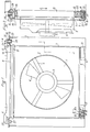
- FIG. 1 designates a grille which is made entirely of metal or synthetic material.
- grid is meant not only what is shown in the drawing and described in the following but also possibly elements such as a bumper shield and made in one piece with the grille, this shield can itself form other parts of the vehicle body.
- the shell delimits a ferrule 2 having an opening 3 in which is arranged a fan 4 driven by an electric motor 5 which is supported by radial arms 6.
- the shell 1 also forms a frame 7 delimiting upper crosspieces 8 and lower 9.
- the cross member 8 has at its ends folded tabs 10, 11 which project forward, beyond the ferrule 2, and which define between them an open part 12, for example a notch whose width is at least equal to the length of the manifold plate 13 - water box 14 assembly of a heat exchanger 15 to be carried by the calender 1.
- the lower cross member 9 of the frame 7 forms at least one cradle 16 and preferably two cradles 16, 17, as shown.
- the cradles 16, 17 also project forward of the grille 1 beyond the ferrule 2.
- a section 9a can be fixed to the cross-member 9 to delimit the cradles 16, 17.
- the heat exchanger 15 fulfills the function of cooler exchanger for the coolant of the engine of a vehicle.
- the illustrated exchanger comprises tubes 18, 18a, ... which are bent in a pin form an elbow 19 and which are threaded through passages of fin tubes 20 or other heat dissipating elements.
- At least some of the bends 19 of the tubes 18, 18a, ... which are located opposite the cradle (s) 16, 17 are provided with elastic shims 21 which also have, as illustrated in section in FIGS. 1 and 2, notches 22 in which the elbows 19 are force-fitted so that they are well fitted together with tight friction and that the elastic wedges 21 cannot escape.
- the cradles 16, 17 when produced by molding can directly form the elastic shims, for example by delimiting ribs tightening the tubes. It is also possible that the elastic shims are formed by molding on the tubes.
- the drawing also shows that the elastic wedges 21 are introduced into the cradles 16, 17 but so as to leave free a space 23 with the bottom of said cradles.
- a space is left free between their bottom and the tubes.
- the manifold plate 13 - water box 14 assembly which can equally be produced in one or more pieces forms on its lateral sides brackets 24, 25 below which protruding pins 26, 27 possibly elastic.
- the pins 26, 27 have flares 28 or other retaining projections.
- Elastic linings 29 are placed in holes in the folded-down legs 10, 11.
- the elastic linings 29 have the shape of a socket and delimit a bearing surface 30 bearing on the top of the legs 10, 11.
- flares 28 of the pins 26, 27 tend to spread the part of the elastic linings 29 which is located under the legs 10, 11 so that vibrations or other stresses cannot allow the heat exchanger 15 to rise. If desired flares 28 can protrude beyond the linings 29.
- the tubes 18, 18a ... can expand more or less but these variations in expansion do not cause any harmful phenomenon because the elastic shims 21 can deform elastically and / or are moved inside the cradle (s) 16, 17 since there is a free space 23 between the underside of the wedges and the cradles.
- the exchanger is in fact elastically connected to the calender 1 and held by snap-fastening and locking of elastic connection means.
- the tabs 10, 11 can themselves form the elastic linings 29, c that is to say that they may have sleeves which may be internally annealed to receive the pins 26, 27.
- pins 26, 27 are replaced or supplemented by elastic metal or plastic clips gripping a bar or other protruding element of the tabs 10, 11 of the upper crossmember. 8 of the grille.
- the invention is not limited to the embodiment shown and described in detail, because various modifications can be made without departing from its scope.
- it can be implemented each time the grille has a passage or well for receiving the heat exchanger without the underside or one side of it being accessible in the mounted position.
- the tabs 10, 11 are located on one side of the grille and that the cradles 16, 17 are thus located on the other lateral side of the grille. This latter arrangement allows the tubes 18 to be arranged horizontally.
Landscapes
- Engineering & Computer Science (AREA)
- Mechanical Engineering (AREA)
- Chemical & Material Sciences (AREA)
- Combustion & Propulsion (AREA)
- Transportation (AREA)
- Physics & Mathematics (AREA)
- Thermal Sciences (AREA)
- General Engineering & Computer Science (AREA)
- Heat-Exchange Devices With Radiators And Conduit Assemblies (AREA)
Abstract
Description
La présente invention concerne un véhicule automobile et plus particulièrement elle est relative à un ensemble combiné incorporant au moins un échangeur de chaleur et au moins une partie de la caisse du véhicule.The present invention relates to a motor vehicle and more particularly it relates to a combined assembly incorporating at least one heat exchanger and at least part of the vehicle body.
La partie de la caisse du véhicule du combiné selon l'invention peut ne comprendre qu'un bâti muni d'un côté d'une virole et d'un support d'au moins un moto-ventilateur ou encore ce même bâti peut être réalisé d'une pièce avec d'autres parties de la caisse ou de la carrosserie du véhicule.The part of the body of the vehicle of the handset according to the invention may comprise only a frame provided on one side with a ferrule and a support for at least one motor-fan, or this same frame can be produced. of a part with other parts of the body or of the vehicle body.
Etant donné que ce qui est dénommé dans ce qui suit par calandre peut être de forme complexe, ainsi qu'il est dit ci-dessus, des difficultés sont apparues pour la mise en place d'au moins un échangeur de chaleur destiné, en particulier, au refroidissement du fluide de circulation utilisé lui-même pour le refroidissement du moteur.Since what is referred to in the following as a calender can be of complex shape, as stated above, difficulties have arisen for the installation of at least one heat exchanger intended, in particular , cooling the circulation fluid itself used for cooling the engine.
L'invention résout ce problème tout en rendant possible la mise en place de l'échangeur par des moyens uniquement mécaniques, c'est-à-dire sans intervention humaine en rendant possible que cette mise en place soit effectuée par un simple mouvement linéaire à trajectoire rectiligne.The invention solves this problem while making possible the installation of the exchanger by only mechanical means, that is to say without human intervention by making it possible that this installation is carried out by a simple linear movement with rectilinear trajectory.
Conformément à l'invention, le combiné calandre échangeur de chaleur dans lequel la calandre est constituée par au moins un bâti comprenant des traverses supérieure et inférieure est caractérisé en ce que la calandre présente une partie ouverte et des pattes rabattues tournées dans le sens opposé à celui d'une virole d'un ventilateur, les pattes délimitant entre elles l'ouverte dont la largeur correspond au moins à la longueur d'un ensemble plaque collectrice boîte à eau d'un échangeur de chaleur, des potences et des moyens d'encliquetage élastiques reliant l'échangeur de chaleur aux pattes et au moins une cale élastique supplémentaire étant prévue entre l'échangeur de chaleur et au moins un berceau formé par la calandre.According to the invention, the combined heat exchanger calender in which the calender consists of at least one frame comprising upper and lower crosspieces is characterized in that the calender has an open part and folded legs turned in the opposite direction to that of a fan shroud, the tabs delimiting between them the opening, the width of which corresponds at least to the length of an assembly of the water box collector plate of a heat exchanger, brackets and elastic latching means connecting the heat exchanger to the legs and at least one additional elastic block being provided between the heat exchanger and at least one cradle formed by the grille.
Diverses autres caractéristiques de l'invention ressortent d'ailleurs de la description détaillée qui suit.Various other characteristics of the invention will also emerge from the detailed description which follows.
Une forme de réalisation de l'objet de l'invention est représentée, à titre d'exemple non limitatif, aux dessins annexés.
- La fig. 1 est une élévation vue depuis l'arrière du combiné calandre échangeur de chaleur objet de l'invention.
- La fig. 2 est une élévation latérale partie en coupe suivant la ligne II-II de la fig. 1.
- Fig. 1 is an elevation seen from the rear of the combined heat exchanger calender object of the invention.
- Fig. 2 is a side elevation partly in section along line II-II of FIG. 1.
1 désigne une calandre qui est réalisée entièrement en métal ou en matière synthétique.1 designates a grille which is made entirely of metal or synthetic material.
Par "calandre", il faut entendre non seulement ce qui est représenté au dessin et décrit dans ce qui suit mais encore éventuellement des éléments tels qu'un bouclier formant pare-chocs et réalisé d'une seule pièce avec la calandre, ce bouclier pouvant lui-même former d'autres parties de la carrosserie d'un véhicule.By "grille" is meant not only what is shown in the drawing and described in the following but also possibly elements such as a bumper shield and made in one piece with the grille, this shield can itself form other parts of the vehicle body.
Dans la représentation des fig. 1 et 2, la calandre délimite une virole 2 présentant une ouverture 3 dans laquelle est disposé un ventilateur 4 entraîné par un moteur électrique 5 qui est supporté par des bras radiaux 6. La calandre 1 forme également un bâti 7 délimitant des traverses supérieure 8 et inférieure 9.In the representation of fig. 1 and 2, the shell delimits a
La traverse 8 présente à ses extrémités des pattes rabattues 10, 11 qui font saillie vers l'avant, au-delà de la virole 2, et qui délimitent entre elles une partie ouverte 12, par exemple une encoche dont la largeur est au moins égale à la longueur de l'ensemble plaque collectrice 13 - boîte à eau 14 d'un échangeur de chaleur 15 devant être porté par la calandre 1.The
La traverse inférieure 9 du bâti 7 forme au moins un berceau 16 et de préférence deux berceaux 16, 17, comme cela est représenté. Les berceaux 16, 17 font également saillie vers l'avant de la calandre 1 au-delà de la virole 2. Un profilé 9a peut être fixé à la traverse 9 pour délimiter les berceaux 16, 17.The
Dans l'exemple repré senté, l'échangeur de chaleur 15 remplit la fonction d'échangeur refroidisseur pour le fluide de refroidissement du moteur d'un véhicule. L'échangeur illustré comporte des tubes 18, 18a, ... qui sont pliés en épingle en formant un coude 19 et qui sont enfilés dans des passages de tubes d'ailettes 20 ou autres éléments dissipateurs de chaleur.In the example shown, the
Certains au moins des coudes 19 des tubes 18, 18a,... qui se trouvent en regard du ou des berceaux 16, 17 sont munis de cales élastiques 21 qui présentent aussi, comme cela est illustré en coupe aux fig. 1 et 2, des encoches 22 dans lesquelles les coudes 19 sont insérés à force de façon qu'ils soient bien emboîtés à frottement serré et que les cales élastiques 21 ne puissent pas s'échapper. Les berceaux 16, 17 lorsqu'ils sont fabriqués par moulage peuvent former directement les cales élastiques par exemple en délimitant des nervures serrant les tubes. Il est possible aussi que les cales élastiques soient formées par moulage sur les tubes.At least some of the
Le dessin montre aussi que les cales élastiques 21 sont introduites dans les berceaux 16, 17 mais de façon à laisser libre un espace 23 avec le fond desdits berceaux. Lorsque les cales 21 sont formées par les berceaux, un espace est laissé libre entre leur fond et les tubes.The drawing also shows that the
L'ensemble plaque collectrice 13 - boîte à eau 14 qui peut indifféremment être réalisé en une ou plusieurs pièces forme sur ses côtés latéraux des potences 24, 25 en dessous desquelles font saillie des pions 26, 27 éventuellement élastiques. Les pions 26, 27 présentent des évasements 28 ou autres saillies de retenue.The manifold plate 13 -
Des garnitures élastiques 29 sont mises en place dans des trous des pattes rabattues 10, 11. Les garnitures élastiques 29 présentent la forme de douille et délimitent une portée 30 prenant appui sur le dessus des pattes 10, 11.
Comme cela ressort de ce qui précède, pour mettre en place l'échangeur de chaleur 15, il suffit de l'engager dans l'encoche 12 de la traverse supérieure 8 puis de le déplacer vers le bas dans le sens de la flèche f₁ de la fig. 2. De cette manière, les cales élastiques 21 sont introduites dans le berceau 16 ou les berceaux 16, 17 et simultanément les pions 26, 27 sont engagés dans les garnitures élastiques 29. En fin de course, l'échangeur de chaleur 15 prend appui sur le dessus des garnitures élastiques 29 par ses potences 24, 25 et en même temps les cales élastiques 21 sont pincées entre les côtés latéraux des berceaux 16 et 17.As is apparent from the above, to set up the
Les évasements 28 des pions 26, 27 tendent à écarter la partie des garnitures élastiques 29 qui se trouve en dessous des pattes 10, 11 de sorte que des vibrations ou d'autres contraintes ne peuvent pas permettre le soulèvement de l'échangeur de chaleur 15. Si on le désire les évasements 28 peuvent faire saillie au-delà des garnitures 29.The
Lors des variations de température que subit l'échangeur de chaleur 15, les tubes 18, 18a ... peuvent se dilater plus ou moins mais ces variations de dilatation n'engendrent aucun phénomène néfaste car les cales élastiques 21 peuvent se déformer élastiquement et/ou sont déplacées à l'intérieur du ou des berceaux 16, 17 puisqu'il existe un espace libre 23 entre le dessous des cales et les berceaux.During the temperature variations undergone by the
Comme cela ressort de ce qui précède, l'échangeur est en fait relié élastiquement à la calandre 1 et maintenu par encliquetage et verrouillage de moyens élastiques de liaison.As is apparent from the above, the exchanger is in fact elastically connected to the
On se sortirait pas du cadre de l'invention en remplaçant les moyens élastiques décrits par d'autres éléments, en particulier lorsque la calandre 1 est fabriquée en matière synthétique, les pattes 10, 11 peuvent former elles-mêmes les garnitures élastiques 29, c'est-à-dire qu'elles peuvent présenter des manchons éventuellement annelés intérieurement pour recevoir les pions 26, 27.We would not go beyond the scope of the invention by replacing the elastic means described by other elements, in particular when the
Il est possible aussi, comme exposé précédemment, que ce soit la calandre qui délimite la ou les cales élastiques 21, la calandre présentant alors des encoches pour recevoi r les coudes des tubes 18, 18a ... .It is also possible, as explained above, that it is the grille which delimits the elastic block (s) 21, the grille then having notches for receiving the elbows of the
On ne sortirait pas non plus du cadre de l'invention en prévoyant que les pions 26, 27 soient remplacés ou complétés par des pinces élastiques métalliques ou en matière plastique venant coiffer une barrette ou autre élément saillant des pattes 10, 11 de la traverse supérieure 8 de la calandre.It would also not depart from the scope of the invention to provide that the
Bien que l'invention ait été décrite dans ce qui précède dans une réalisation comportant un échangeur de chaleur 15 à tube en épingle, elle peut être mise en oeuvre de semblable façon avec un échangeur conventionnel comprenant deux ensembles à plaque collectrice en boîte à eau. En effet, dans ce cas, la boîte à eau inférieure correspondrait aux coudes 19 des tubes 18, 18a ... et pourrait être maintenue de même manière dans les berceaux 16, 17.Although the invention has been described in the foregoing in an embodiment comprising a
L'invention n'est pas limitée à l'exemple de réalisation représenté et décrit en détail, car diverses modifications peuvent y être apportées sans sortir de son cadre. En particulier, elle peut être mise en oeuvre chaque fois que la calandre présente un couloir ou puits pour recevoir l'échangeur de chaleur sans que le dessous ou un côté de celui-ci soit accessible en position montée. Il est en effet possible dans le cadre de l'invention que les pattes 10, 11 se trouvent sur un côté de la calandre et que les berceaux 16, 17 se trouvent de la sorte sur l'autre côté latéral de la calandre. Cette dernière disposition permet que les tubes 18 soient disposés horizontalement. The invention is not limited to the embodiment shown and described in detail, because various modifications can be made without departing from its scope. In particular, it can be implemented each time the grille has a passage or well for receiving the heat exchanger without the underside or one side of it being accessible in the mounted position. It is indeed possible within the framework of the invention that the
Claims (11)
Applications Claiming Priority (2)
| Application Number | Priority Date | Filing Date | Title |
|---|---|---|---|
| FR8613585 | 1986-09-30 | ||
| FR8613585A FR2604403B1 (en) | 1986-09-30 | 1986-09-30 | HEAT EXCHANGER CALENDER COMBINATION |
Publications (1)
| Publication Number | Publication Date |
|---|---|
| EP0263732A1 true EP0263732A1 (en) | 1988-04-13 |
Family
ID=9339386
Family Applications (1)
| Application Number | Title | Priority Date | Filing Date |
|---|---|---|---|
| EP87402050A Withdrawn EP0263732A1 (en) | 1986-09-30 | 1987-09-15 | Combined radiator shell and heat exchanger |
Country Status (2)
| Country | Link |
|---|---|
| EP (1) | EP0263732A1 (en) |
| FR (1) | FR2604403B1 (en) |
Cited By (4)
| Publication number | Priority date | Publication date | Assignee | Title |
|---|---|---|---|---|
| EP0354387A2 (en) * | 1988-08-06 | 1990-02-14 | Adam Opel Aktiengesellschaft | Front crossbeam |
| EP0494353A2 (en) * | 1990-12-11 | 1992-07-15 | Behr GmbH & Co. | Cooling unit for a vehicle engine |
| GB2299158A (en) * | 1995-03-21 | 1996-09-25 | Valeo Uk | Method and apparatus for securing a fan motor and heat exchanger to a structure |
| EP0870638A1 (en) * | 1997-04-09 | 1998-10-14 | Valeo Thermique Moteur S.A. | Collecting box for a heat exchanger, especially in a motor vehicle |
Citations (3)
| Publication number | Priority date | Publication date | Assignee | Title |
|---|---|---|---|---|
| GB877353A (en) * | 1959-03-31 | 1961-09-13 | Serck Radiators Ltd | Improvements in mountings for air-cooled radiators |
| FR2336268A1 (en) * | 1975-12-22 | 1977-07-22 | Daimler Benz Ag | VEHICLE RADIATOR MOUNTING SYSTEM, ESPECIALLY AUTOMOTIVE |
| DE2634990A1 (en) * | 1976-08-04 | 1978-02-09 | Audi Nsu Auto Union Ag | Elastic mounting for vehicle radiator - has studs with elastic grommets to press into mounting holes in body |
-
1986
- 1986-09-30 FR FR8613585A patent/FR2604403B1/en not_active Expired
-
1987
- 1987-09-15 EP EP87402050A patent/EP0263732A1/en not_active Withdrawn
Patent Citations (3)
| Publication number | Priority date | Publication date | Assignee | Title |
|---|---|---|---|---|
| GB877353A (en) * | 1959-03-31 | 1961-09-13 | Serck Radiators Ltd | Improvements in mountings for air-cooled radiators |
| FR2336268A1 (en) * | 1975-12-22 | 1977-07-22 | Daimler Benz Ag | VEHICLE RADIATOR MOUNTING SYSTEM, ESPECIALLY AUTOMOTIVE |
| DE2634990A1 (en) * | 1976-08-04 | 1978-02-09 | Audi Nsu Auto Union Ag | Elastic mounting for vehicle radiator - has studs with elastic grommets to press into mounting holes in body |
Cited By (8)
| Publication number | Priority date | Publication date | Assignee | Title |
|---|---|---|---|---|
| EP0354387A2 (en) * | 1988-08-06 | 1990-02-14 | Adam Opel Aktiengesellschaft | Front crossbeam |
| EP0354387A3 (en) * | 1988-08-06 | 1990-10-17 | Adam Opel Aktiengesellschaft | Front crossbeam |
| EP0494353A2 (en) * | 1990-12-11 | 1992-07-15 | Behr GmbH & Co. | Cooling unit for a vehicle engine |
| EP0494353A3 (en) * | 1990-12-11 | 1993-12-01 | Behr Gmbh & Co | Cooling unit for a vehicle engine |
| GB2299158A (en) * | 1995-03-21 | 1996-09-25 | Valeo Uk | Method and apparatus for securing a fan motor and heat exchanger to a structure |
| GB2299158B (en) * | 1995-03-21 | 1999-08-04 | Valeo Uk | Fan and heat exchanger support bracket |
| EP0870638A1 (en) * | 1997-04-09 | 1998-10-14 | Valeo Thermique Moteur S.A. | Collecting box for a heat exchanger, especially in a motor vehicle |
| FR2762077A1 (en) * | 1997-04-09 | 1998-10-16 | Valeo Thermique Moteur Sa | COLLECTOR BOX OF A HEAT EXCHANGER, PARTICULARLY IN A MOTOR VEHICLE, AND METHOD FOR REPAIRING THE BOX |
Also Published As
| Publication number | Publication date |
|---|---|
| FR2604403B1 (en) | 1988-12-30 |
| FR2604403A1 (en) | 1988-04-01 |
Similar Documents
| Publication | Publication Date | Title |
|---|---|---|
| EP1067005B1 (en) | Arrangement for fastening modules to a support in a motor vehicle | |
| FR2785379A1 (en) | HEAT EXCHANGE MODULE COMPRISING A FAN NOZZLE AND A HEAT EXCHANGER, PARTICULARLY FOR A MOTOR VEHICLE | |
| FR2793741A1 (en) | Mechanism for fitting radiator in car comprises support and fixing ring, which is attached in rotation on support through coaxial apertures | |
| EP0263732A1 (en) | Combined radiator shell and heat exchanger | |
| FR2825964A1 (en) | Front end of motor vehicle with integrated fittings, uses side pods to accommodate head lamp housings and has top and bottom rails that attach to side rails of vehicle structure | |
| EP1089048A1 (en) | Device for assembling an insert with a heat exchanger, more particularly for automotive vehicle | |
| FR2699962A1 (en) | Cooling module of an internal combustion engine of motor vehicles. | |
| FR2752108A1 (en) | IMPROVED DEVICE FOR ELASTIC FIXING OF AN ELECTRIC MOTOR, PARTICULARLY FOR A MOTOR VEHICLE | |
| EP0647824B1 (en) | Heat exchanger used more particularly as oil cooler | |
| EP1457684B1 (en) | Cooling unit with radial tension ring for the ventilator motor, cooling unit for front part, and vehicle equipped with such a cooling unit | |
| WO2018172710A1 (en) | Cooling device for the battery of a motor vehicle | |
| EP0780584A1 (en) | Device for fixing in place a heat exchanger for a vehicle heating and/or air conditioning installation | |
| FR2745075A1 (en) | HEAT EXCHANGER COMPRISING A TUBULAR BLOCK WITH FINS | |
| EP0478403A1 (en) | Mounting arrangement of a cooling radiator for a vehicle motor | |
| FR2822941A1 (en) | SIMPLIFIED MOUNT HEAT EXCHANGE MODULE FOR MOTOR VEHICLE | |
| FR2677937A1 (en) | FIXING STRUCTURE FOR ATTACHING PIECE FOR MODULAR WIPING APPARATUS. | |
| FR2768261A1 (en) | BASE FOR MOTOR VEHICLE ALTERNATOR POWER DIODE | |
| EP0193423B1 (en) | Heat exchanger with u-shaped tubes | |
| FR2800862A1 (en) | COOLING FLUID RADIATOR COMPRISING A COMPENSATION TANK | |
| FR2526932A1 (en) | HEAT EXCHANGER SUCH AS A MOTOR VEHICLE RADIATOR | |
| FR3064404A1 (en) | COOLING DEVICE FOR MOTOR VEHICLE BATTERIES | |
| FR2852156A1 (en) | Pipe support for supporting electrical wires in raceway, has two lateral flanges spreading from base to free end, where free end is covered by rigid profile e.g. folded sheet, integrated to flange | |
| FR2781724A1 (en) | Electrical motor support for a vehicle heater or air conditioning system comprising an integral cylindrical housing for the motor | |
| WO2016042231A1 (en) | Cooling assembly for a functional member to be cooled comprising a radiator and a motor-fan support | |
| FR2841974A1 (en) | EQUIPMENT AND METHOD FOR MOUNTING A HEAT EXCHANGER, PARTICULARLY FOR A MOTOR VEHICLE |
Legal Events
| Date | Code | Title | Description |
|---|---|---|---|
| PUAI | Public reference made under article 153(3) epc to a published international application that has entered the european phase |
Free format text: ORIGINAL CODE: 0009012 |
|
| 17P | Request for examination filed |
Effective date: 19870918 |
|
| AK | Designated contracting states |
Kind code of ref document: A1 Designated state(s): DE ES FR GB IT |
|
| 17Q | First examination report despatched |
Effective date: 19890907 |
|
| RAP1 | Party data changed (applicant data changed or rights of an application transferred) |
Owner name: VALEO THERMIQUE MOTEUR |
|
| STAA | Information on the status of an ep patent application or granted ep patent |
Free format text: STATUS: THE APPLICATION IS DEEMED TO BE WITHDRAWN |
|
| 18D | Application deemed to be withdrawn |
Effective date: 19900323 |
|
| RIN1 | Information on inventor provided before grant (corrected) |
Inventor name: LEGAUYER, PHILIPPE |