EP0263644B1 - Method for investigating drag and torque loss in the drilling process - Google Patents
Method for investigating drag and torque loss in the drilling process Download PDFInfo
- Publication number
- EP0263644B1 EP0263644B1 EP87308701A EP87308701A EP0263644B1 EP 0263644 B1 EP0263644 B1 EP 0263644B1 EP 87308701 A EP87308701 A EP 87308701A EP 87308701 A EP87308701 A EP 87308701A EP 0263644 B1 EP0263644 B1 EP 0263644B1
- Authority
- EP
- European Patent Office
- Prior art keywords
- drill string
- torque
- weight
- bit
- determining
- Prior art date
- Legal status (The legal status is an assumption and is not a legal conclusion. Google has not performed a legal analysis and makes no representation as to the accuracy of the status listed.)
- Expired - Lifetime
Links
Images


Classifications
-
- E—FIXED CONSTRUCTIONS
- E21—EARTH DRILLING; MINING
- E21B—EARTH DRILLING, e.g. DEEP DRILLING; OBTAINING OIL, GAS, WATER, SOLUBLE OR MELTABLE MATERIALS OR A SLURRY OF MINERALS FROM WELLS
- E21B44/00—Automatic control systems specially adapted for drilling operations, i.e. self-operating systems which function to carry out or modify a drilling operation without intervention of a human operator, e.g. computer-controlled drilling systems; Systems specially adapted for monitoring a plurality of drilling variables or conditions
Definitions
- This invention relates to the field of measurements while drilling, and more specifically to planning and analysis of the drilling process.
- Drag and torque loss affect the drilling of all hydrocarbon wells, and are especially problematic in deviated wells. Drag manifests itself as an extra load over and above the rotating string weight when tripping out of the hole. Torsional loss from the rotating drill string while drilling causes the power available for rock destruction to be considerably lower than that applied at the rotary table. Problems of drag and torque loss normally occur together and can be particularly marked in long reach wells.
- the side force profile is essentially determined by well geometry, and can be broadly divided into the effects of poor hole conditions or inappropriate mud weight, and effects of the well path itself.
- the conditions under which an earth boring apparatus such as a conventional drill bit operates are analyzed by measuring the torque applied at the surface to the drill string and the effective torque acting on the drill bit.
- the applied torque and effective torque are compared to determine torque loss.
- applied weight on the drill string and effective weight acting on the drill bit may be measured and compared to determine drag losses.
- These measurements and comparisons may be done in real-time to diagnose unfavorable drilling conditions, or to assist the driller in decisions such as whether to trip out to change a bottom hole assembly, or to attempt a hole cleaning process such as a wiper trip, or to perform other procedures.
- the torque or weight measurements may be used to calculate a variable coefficient of friction acting on the drilling string. Trends in the torque or weight losses, or in the value of the coefficient of friction, may be observed on a plot of these quantities as a function of depth.
- the present invention thus provides a method for analyzing torque and weight transfer along a drill string, to give the driller an enhanced insight into drilling efficiency and problem situations in the drilling process.
- the real-time analysis may be performed with the bit on bottom by detecting and interpreting trends of abnormal torque transfers.
- Abnormal weight transfers are analyzed based on hookload and weight transfer analysis.
- the techniques of the present invention produce expected trends for weight and torque transfers in a given environment including the well profile, the bottom hole assembly design, the lithological sequence and the mud program. Weight and torque losses for several such drilling plans may be calculated, so that the most favorable plan may be chosen.
- an apparatus suitable for performing a method according to a preferred embodiment of the invention includes a measurement-while-drilling (MWD) tool 10 dependently coupled to the end of a drill string 11 comprised of one or more drill collars 12 and a plurality of tandemly connected joints 13 of drill pipe.
- Earth boring means such as a conventional drill bit 14, are positioned below the MWD tools.
- the drill string 11 is rotated by a rotary table 16 on a conventional drilling rig 15 at the surface. Mud is circulated through the drill string 11 and bit 14 in the direction of the arrows 17 and 18.
- the tool 10 further comprises a plurality of heavy walled tubular bodies which are tandemly coupled to enclose weight and torque measuring means 20 adapted for measuring the torque and weight acting on the drill bit 14, as well as typical position measuring means 21 adapted for measuring parameters such as the direction and inclination of the tool 10 so as to indicate its spatial position.
- Typical data signaling means 22 are adapted for transmitting encoded acoustic signals representative of the output of the sensors 20 and 21 to the surface through the downwardly flowing mud stream in the drill string 11. These acoustic signals are converted to electrical signals by a transducer 34 at the surface. The electrical signals will be analyzed by appropriate data processing means 33 at the surface.
- a total depth sensor (not shown) is provided to allow for the correlation of measurements made during the drilling and tripping modes.
- the external body 24 of the force-measuring means 20 of a preferred embodiment is depicted somewhat schematically to illustrate the spatial relationships of the measurement axes of the body as the force-measuring means 20 measure weight and torque acting on the drill bit 14 during a typical drilling operation.
- the thick-walled tubular body 24 is cooperatively arranged as a separate sub that can be mounted just above the drill bit 14 for obtaining more accurate measurements of the various forces acting on the bit.
- housings such as, for example, those shown in U.S. Patent No. 3,855,857 or U.S. Patent No. 4,359,898 could be used as depicted there or with modifications as needed for devising alternative embodiments of force-measuring apparatus suitable for use in the appartus and method of the present invention.
- the body 24 has a longitudinal or axial bore 25 of an appropriate diameter for carrying the stream of drilling mud flowing through the drill string 11.
- the body 24 is provided with a set of radial openings, B1, B2, B3 and B4, having their axes all lying in a transverse plane that intersects the longitudinal Z-axis 26 of the body. It will, of course, be recognized that in the depicted arrangement of the body 24 of the force-measuring means 20, these openings are cooperatively positioned so that they are respectively aligned with one another in the transverse plane that perpendicularly intersects the Z-axis 26 of the body.
- one pair of the holes B1 and B3, are respectively located on opposite sides of the body 24 and axially aligned with each other so that their respective central axes lie in the transverse plane and together define an X-axis 27 that is perpendicular to the Z-axis 26 of the body.
- the other two openings B2 and B4 are located in diametrically-opposite sides of the body 24 and are angularly offset by 90 degrees from the first set of openings B1 and B3 so that their aligned central axes respectively define the Y-axis 28 perpendicular to the Z-axis 26 as well as the X-axis 27.
- FIGURE 4 an isometric view is shown of the openings B1-B4, the X-axis 27, the Y-axis 28 and the Z-axis 26.
- force-sensing means are mounted in each quadrant of the openings B1 and B2.
- these force-sensing means (such as typical strain gauges 401 a-401 and 403a-403d) are respectively mounted at the 0-degrees, 90-degrees, 180-degrees and 270-degrees positions within the openings B1 and B3.
- rotational force-sensing means such as typical strain gauges 402a-402d and 404a-404d, are mounted in each quadrant of the openings B2 and B4. As depicted, it has been found that maximum sensitivity is provided by mounting the strain gauges 402a-402d at the 45-degrees, 135-degrees, 223-degrees and 315-degrees positions in the opening B2 and by mounting the other strain gauges 404a-404d at the same angular positions in the opening B4.
- Measurement of the weight-on-bit is, therefore, obtained by arranging the several strain gauges 401a-401d and 403a-403d In a typical Wheatstone bridge B1-B3 to provide corresponding output signals (Le., WOB).
- the torque measurements are obtained by connecting the several gauges 402a-402d and 404a-404d into another bridge B2-B4 that produces corresponding output signals (i.e., torque).
- the several sensors described by reference to FIGURE 3 can be mounted in various arrangements on the body 24.
- the force sensors 401 a and 401 b are each mounted at their respective optimum locations in the same openings as are the torque sensors 402a-402d.
- the several sensors located in the opening B1 are each secured to the body 24 in a typical manner such as with a suitable adhesive.
- Other sensors 201 a and 201 b for example, may also be so mounted.
- mount one or more terminal strips 31 and 32 in each of the several openings to facilitate the interconnection of the force sensors in any given opening to one another as well as to provide convenient terminal that will facilitate connecting the sensors to various conductors 33 leading to the measuring circuitry in the MWD tool 10 (not seen in FIGURE 5).
- the several force sensors be protected from the borehole fluids and the extreme pressures and temperatures normally encountered in boreholes by sealing the sensors within their respective openings B1-B4 by means of typical fluid-tight closure members (not shown in the drawings).
- the enclosed spaces defined in these openings and their associated interconnecting wire passages are usually filled with a suitable oil that is maintained at an elevated pressure by means such as a piston or other typical pressure-compensating member that is responsive to borehole conditions.
- Standard feed through connectors (not shown in the drawings) are arranged as needed for interconnecting the conductors in these sealed spaces with their corresponding conductors outside of the oil- filled spaces.
- a tension T and torque TOR act on the downhole end of an incremental length of drill string 40, while an uphole tension T+dT and torque TOR+d(TOR) act on the uphole end.
- a buoyancy force Fb acts in an upward vertical direction while a gravitational force Fg acts in an opposing direction.
- An additional side force component due to stiffness of the drill string can be computed using the theory of bending and twisting of elastic rods. Models using such theories are known to those having ordinary skills in the art, and are contained in the literature associated with this field. One such model is discussed in Jogi et al, "Three Dimensional Bottomhole Assembly Model Improves Directional Drilling," SPE Paper No. 14768, February, 1986. This component may, if desired, be added to Tn in equation (1) to correct for stiffness of the drill string.
- a drag force acts along the length of the drill string increment 40, and is assumed to be proportional to the side force Tn acting on the drill string.
- the proportionality coefficient ⁇ (s) (which is not necessarily constant but may be a function of the distance s from the bit) appears in this model as a sliding friction coefficient.
- the resulting frictional force u(s)Tn acts against the motion of the drill string increment 40, leading to drag while tripping out and torque lose while rotating.
- the friction profile tt(s) can be calculated on an incremental basis as follows:
- equations (1) and (4) provide the elements of an incremental (generally numerical) solution for the effective tension T(s).
- the evaluation of T(s) at the surface gives the hook load, and the overpull is the difference between the hook load and the free rotating weight of the drill string.
- a preferred embodiment of the invention described here proposes a running calculation of the friction profile ⁇ (s). This has the effect of generating a far more sensitive characterization of the frictional effects than is provided by the global friction approach which effectively smears local effects over the entire drill string.
- This quantity yields useful information about how drilling is progressing. For example, if the bottom hole assembly remains unchanged, then an increase in the coefficient of friction indicates a change in hole condition, hole shape or lithology, or a malfunction of the bottom hole assembly.
- the quantity is preferrably calculated and recorded as a function of depth while drilling (or tripping) progresses, to produce a log useful in the diagnosing of drilling or well bore problems.
- Values for HKLD and DWOB, as well as STOR and DTOR, can be compared at successive depths to determine torque and weight losses. Such losses, as is the quantity ⁇ , are preferably correlated with depth and recorded as a function of depth on a log. Trends and changes can then be observerd.
- FIGURES 6, 7 and 8 show an illustrative example of how a method according to a preferred embodiment of the invention may be used. These figures show logs obtained according to a preferred embodiment of the present invention in a relatively straight well having a constant inclination.
- FIGURE 7 shows a log of weight and torque losses, computed from inputs taken from the DATA log of Figure 6.
- Track 1 of the WEIGHT AND TORQUE LOSSES log shows the calculated free rotating hookload (THDC).
- Track 2 shows the weight-on-bit losses between surface and downhole (WODC). The best weight transfer is achieved in the section from A-A to B-B when WODC is minimal.
- the torque transfer (TODM) the difference between the measured surface torque and the measured downhole torque, is shown in Track 3.
- the ANALYSIS log was produced in order to investigate explanations for weight-on-bit and torque transfer problems related to hole stability and crookedness. Correlations were sought between weight-on-bit and torque transfer and drilling practice (especially off bottom periods between the drilling sequences), lithology, and bottomhole assembly configuration.
- the ANALYSIS leg in FIGURE 8 clearly shows the effectiveness of the reaming when the joint is drilled out in the WODC track, which shows an improved weight transfer when the drilling is resumed at C-C.
- This log also shows that the weight-on-bit transfer is better in the less argileaous sections up to C-C.
- the transfer decreases when the clay content increases between C-C and D-D.
- a circulation exceeding 20 minutes was done at C-C is shown to drastically increase the transfer, Off bottom time at C-C exceeded 50 minutes, for a wiper trip.
- the C-C level is also the level where the last stabilizer reached a cleaner limestone section starting at B-B. Trends can be seen on the log which reflect the overall interaction between the borehole walls and the drillstring.
- the ANALYSIS log shows the friction factor correction FFDC due to weight-on-bit loss to be, in effect a normalization of the weight-on-bit transfer WODC, since the FFDC track follows the trends of the weight-on-bit transfer track.
- Equations (2) and (3) can be used for well planning by assuming a constant value for over a portion of a well and calculating the torsional and drag losses which should be expected for a given trajectory.
- the assumed value for may be chosen from knowledge of wells in similar lithologies, as in the case of multiple wells drilled from a single platform.
- a value of 0.3 as an estimate of has been found to work satisfactorily for comparison purposes where torque and drag losses for several trajectories are computed and compared to determine the optimal trajectory. It would also be possible to assume a particular functional form for l i(s) and an initial value to arrive at torque and drag loss.
- FIGURE 9 shows an example of a graphical representation of calculation results which is useful in well planning.
- trends in the torque and weight parameters are shown for the drilling ahead of a well from 2,286 meters (7,500 feet) to 4,572 meters (15,00 feet).
- the coefficient of friction was assumed to be a constant 0.3
- weight-on-bit was taken to be a constant 13,608 kilograms (30 kilopounds).
- the weight transfer was assumed complete, so that the surface and downhole weight-on-bit are the same.
- the buoyant drill string weight i.e., the weight of the drill string immersed in mud, was calculated and is indicated by curve 42.
- the rotating string load, indicated by curve 43 is the drill string tension under the hook while rotating.
- This quantity includes the effect of inclination of sections of the well.
- the increase in buoyant weight and rotating string load is linear due to the addition of a single type of drill pipe while drilling this portion of the well.
- the torque losses represent the difference between the surface and the downhole torque.
- the shape of the torque loss curve 44 is due to different grades of drill pipe used within the string. For example, the section of lower increase in torque loss (2,895 meters to 3,810 meters or 9,500 feet to 12,500 feet) shows the effect of using 914 meters (3,000 feet) of aluminium drill pipe within the string.
- the expected loads and torque losses for a particular drill string and bottomhole assembly can be predicted, and the appropriateness of particular equipment configurations can be assessed.
Description
- This invention relates to the field of measurements while drilling, and more specifically to planning and analysis of the drilling process.
- Drag and torque loss affect the drilling of all hydrocarbon wells, and are especially problematic in deviated wells. Drag manifests itself as an extra load over and above the rotating string weight when tripping out of the hole. Torsional loss from the rotating drill string while drilling causes the power available for rock destruction to be considerably lower than that applied at the rotary table. Problems of drag and torque loss normally occur together and can be particularly marked in long reach wells.
- There are a variety of sources of drag and torque loss including differential sticking, keyseating, hole instabilities, poor hole cleaning, and the frictional interaction associated with side forces along the drill string. The side force profile is essentially determined by well geometry, and can be broadly divided into the effects of poor hole conditions or inappropriate mud weight, and effects of the well path itself.
- U.S. Patent No. 4,549,431 to Soeiinah (assigned to Mobil Oil Corporation) discloses a method of detecting some of these problems in the drilling of a well from uphole measurements of hook load and free rotating torque. But experience has shown that noticeable differences occur between the torque and weight applied at the surface and that effectively applied at the bit, especially in areas of potential drilling problems. Likewise, the hookload values and the weight of the drill string in mud usually differ. Thus, the technique of the Soeiinah patent has serious inherent limitations.
- The 1983 paper, "Torque and Drag in Directional Wells -- Prediction and Measurement," by C. A. Johancsik, D. B. Friesen, and Rapier Dawson (IADC/SPE 1983 Drilling Conference, Paper No. 11380), proposed a computer model of drill string torque and drag, but like the Soeiinah method, this model suffers from failure to analyze downhole torque and weight parameters.
- Because the available techniques lack a way of investigating and analyzing downhole torque and weight on bit, which may differ significantly from the corresponding surface measurements of torque and hookload, there remains a gap between planned optimization of a drilling program and its implementation. Thus, a need has arisen for a new technique by which torque and weight transfer along the drill string can be analyzed, both in real-time for diagnosis of drilling problems and in advance for planning.
- In a preferred embodiment of the invention, the conditions under which an earth boring apparatus such as a conventional drill bit operates are analyzed by measuring the torque applied at the surface to the drill string and the effective torque acting on the drill bit. The applied torque and effective torque are compared to determine torque loss. Likewise, applied weight on the drill string and effective weight acting on the drill bit may be measured and compared to determine drag losses. These measurements and comparisons may be done in real-time to diagnose unfavorable drilling conditions, or to assist the driller in decisions such as whether to trip out to change a bottom hole assembly, or to attempt a hole cleaning process such as a wiper trip, or to perform other procedures. The torque or weight measurements may be used to calculate a variable coefficient of friction acting on the drilling string. Trends in the torque or weight losses, or in the value of the coefficient of friction, may be observed on a plot of these quantities as a function of depth.
- In addition to this real-time analysis, it is a further embodiment of the invention to plan or predict what is to be expected in a drilling process by assuming predetermined values for the coefficient of friction for the hole as a function of depth and calculating therefrom the torque and drag losses which are to be expected.
- The present invention thus provides a method for analyzing torque and weight transfer along a drill string, to give the driller an enhanced insight into drilling efficiency and problem situations in the drilling process. In a preferred embodiment of the invention, the real-time analysis may be performed with the bit on bottom by detecting and interpreting trends of abnormal torque transfers. Abnormal weight transfers are analyzed based on hookload and weight transfer analysis. These techniques can be used alone or in combination to diagnose and quantify drilling problems related to drag and torque loss.
- As a planning tool, the techniques of the present invention produce expected trends for weight and torque transfers in a given environment including the well profile, the bottom hole assembly design, the lithological sequence and the mud program. Weight and torque losses for several such drilling plans may be calculated, so that the most favorable plan may be chosen.
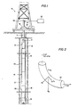
- FIGURE 1 shows a preferred embodiment of an apparatus according to the present invention as it may appear while practicing the method of a preferred embodiment of the invention while drilling;
- FIGURE 2 shows a schematic diagram of a torque and tension model as used in the preferred embodiment of the invention;
- FIGURE 3 is an isometric view of a preferred embodiment of a force measuring means in the Figure 1 embodiment;
- FIGURE 4 is a schematic representation of the force measuring means shown in FIGURE 3 showing preferred locations for various sets of force sensors and bridge circuits associated with these sensors;
- FIGURE 5 is an enlarged view of one portion of the force measuring means of FIGURE 2 illustrating a preferred mounting arrangement for the force sensors;
- FIGURE 6 shows a log of data obtained in a well with an apparatus and method according to a preferred embodiment of the invention;
- FIGURE 7 shows a log of weight and torque losses; and
- FIGURE 8 shows a log correlating weight and torque loss to drilling practices, lithology and bottomhole assembly.
- FIGURE 9 shows a graphical representation of calculations of various load parameters in accordance with the present invention.
- Turning now to Figure 1, an apparatus suitable for performing a method according to a preferred embodiment of the invention includes a measurement-while-drilling (MWD)
tool 10 dependently coupled to the end of adrill string 11 comprised of one ormore drill collars 12 and a plurality of tandemly connectedjoints 13 of drill pipe. Earth boring means, such as a conventional drill bit 14, are positioned below the MWD tools. Thedrill string 11 is rotated by a rotary table 16 on aconventional drilling rig 15 at the surface. Mud is circulated through thedrill string 11 and bit 14 in the direction of thearrows - As depicted in Figure 1, the
tool 10 further comprises a plurality of heavy walled tubular bodies which are tandemly coupled to enclose weight and torque measuring means 20 adapted for measuring the torque and weight acting on the drill bit 14, as well as typicalposition measuring means 21 adapted for measuring parameters such as the direction and inclination of thetool 10 so as to indicate its spatial position. Typical data signaling means 22 are adapted for transmitting encoded acoustic signals representative of the output of thesensors drill string 11. These acoustic signals are converted to electrical signals by atransducer 34 at the surface. The electrical signals will be analyzed by appropriate data processing means 33 at the surface. - Conventional sensors for measuring hookload and torque applied to the drill string, 36 and 37 respectively, are located at the surface. A total depth sensor (not shown) is provided to allow for the correlation of measurements made during the drilling and tripping modes.
- Turning now to FIGURE 3, the
external body 24 of the force-measuring means 20 of a preferred embodiment is depicted somewhat schematically to illustrate the spatial relationships of the measurement axes of the body as the force-measuring means 20 measure weight and torque acting on the drill bit 14 during a typical drilling operation. Rather than making the force-measuring means 20 an integral portion of theMWD tool 10, in a preferred embodiment, the thick-walledtubular body 24 is cooperatively arranged as a separate sub that can be mounted just above the drill bit 14 for obtaining more accurate measurements of the various forces acting on the bit. It will, or course, be appreciated that other types of housings such as, for example, those shown in U.S. Patent No. 3,855,857 or U.S. Patent No. 4,359,898 could be used as depicted there or with modifications as needed for devising alternative embodiments of force-measuring apparatus suitable for use in the appartus and method of the present invention. - As seen in FIGURE 3, the
body 24 has a longitudinal oraxial bore 25 of an appropriate diameter for carrying the stream of drilling mud flowing through thedrill string 11. Thebody 24 is provided with a set of radial openings, B1, B2, B3 and B4, having their axes all lying in a transverse plane that intersects the longitudinal Z-axis 26 of the body. It will, of course, be recognized that in the depicted arrangement of thebody 24 of the force-measuring means 20, these openings are cooperatively positioned so that they are respectively aligned with one another in the transverse plane that perpendicularly intersects the Z-axis 26 of the body. For example, as illustrated, one pair of the holes B1 and B3, are respectively located on opposite sides of thebody 24 and axially aligned with each other so that their respective central axes lie in the transverse plane and together define anX-axis 27 that is perpendicular to the Z-axis 26 of the body. In like fashion, the other two openings B2 and B4 are located in diametrically-opposite sides of thebody 24 and are angularly offset by 90 degrees from the first set of openings B1 and B3 so that their aligned central axes respectively define the Y-axis 28 perpendicular to the Z-axis 26 as well as theX-axis 27. - Turning now to FIGURE 4, an isometric view is shown of the openings B1-B4, the
X-axis 27, the Y-axis 28 and the Z-axis 26. As depicted, to measure the longitudinal force acting downwardly on thebody member 24 in order to determine the effective weight-on-bit, force-sensing means are mounted in each quadrant of the openings B1 and B2. To achieve maximum sensitivity, these force-sensing means (such as typical strain gauges 401 a-401 and 403a-403d) are respectively mounted at the 0-degrees, 90-degrees, 180-degrees and 270-degrees positions within the openings B1 and B3. In a like fashion, to measure the rotational torque imposed on thebody member 24, rotational force-sensing means, such astypical strain gauges 402a-402d and 404a-404d, are mounted in each quadrant of the openings B2 and B4. As depicted, it has been found that maximum sensitivity is provided by mounting thestrain gauges 402a-402d at the 45-degrees, 135-degrees, 223-degrees and 315-degrees positions in the opening B2 and by mounting theother strain gauges 404a-404d at the same angular positions in the opening B4. Measurement of the weight-on-bit is, therefore, obtained by arranging theseveral strain gauges 401a-401d and 403a-403d In a typical Wheatstone bridge B1-B3 to provide corresponding output signals (Le., WOB). In a like manner, the torque measurements are obtained by connecting theseveral gauges 402a-402d and 404a-404d into another bridge B2-B4 that produces corresponding output signals (i.e., torque). - Those skilled in the art will, of course, appreciate that the several sensors described by reference to FIGURE 3 along with other force measuring sensors as desired for other purposes, can be mounted in various arrangements on the
body 24. However, it has been found most advantageous to mount the several force sensors in the openings B1-B4 in such a manner that although the force sensors in a given opening are separated from one another, each sensor is located in an optimum position for providing the best possible response. For example, as depicted in the developed view of the opening B1 seen in FIGURE 5, theforce sensors torque sensors 402a-402d. It will, or course, be recognized that the several sensors located in the opening B1 are each secured to thebody 24 in a typical manner such as with a suitable adhesive.Other sensors means 20 it has also been found advantageous to mount one or moreterminal strips various conductors 33 leading to the measuring circuitry in the MWD tool 10 (not seen in FIGURE 5). - As is typical, it is preferred that the several force sensors be protected from the borehole fluids and the extreme pressures and temperatures normally encountered in boreholes by sealing the sensors within their respective openings B1-B4 by means of typical fluid-tight closure members (not shown in the drawings). The enclosed spaces defined in these openings and their associated interconnecting wire passages are usually filled with a suitable oil that is maintained at an elevated pressure by means such as a piston or other typical pressure-compensating member that is responsive to borehole conditions. Standard feed through connectors (not shown in the drawings) are arranged as needed for interconnecting the conductors in these sealed spaces with their corresponding conductors outside of the oil- filled spaces.
- Turning now the principles of operation of the present invention, in a preferred embodiment, torque and weight transfer are analyzed using a dynamic torque and tension model diagrammed in FIGURE 2. In this model, a tension T and torque TOR act on the downhole end of an incremental length of
drill string 40, while an uphole tension T+dT and torque TOR+d(TOR) act on the uphole end. A buoyancy force Fb acts in an upward vertical direction while a gravitational force Fg acts in an opposing direction. These forces all contribute to a resultant side force Tn acting in a direction perpendicular to a plane tangent to the incrementaldrill string length 40. - The side force Tn given by the equation

- An additional side force component due to stiffness of the drill string can be computed using the theory of bending and twisting of elastic rods. Models using such theories are known to those having ordinary skills in the art, and are contained in the literature associated with this field. One such model is discussed in Jogi et al, "Three Dimensional Bottomhole Assembly Model Improves Directional Drilling," SPE Paper No. 14768, February, 1986. This component may, if desired, be added to Tn in equation (1) to correct for stiffness of the drill string.
- A drag force acts along the length of the
drill string increment 40, and is assumed to be proportional to the side force Tn acting on the drill string. The proportionality coefficient µ(s) (which is not necessarily constant but may be a function of the distance s from the bit) appears in this model as a sliding friction coefficient. The resulting frictional force u(s)Tn acts against the motion of thedrill string increment 40, leading to drag while tripping out and torque lose while rotating. -
- Consider that the well has been drilled to some pipe depth D and that the friction µD(s) down to this point is known (having been calculated in previous increments). The well is now drilled to a pipe depth D+o and the friction coefficient µo for this last segment is to be calculated (we must assume the go is a constant over this last segment). The effective tension while rotating, at some height s above the bit is given by

s ) is the buoyed weight per unit length of the tubulars and e (5) is the inclination ats obtained from survey data (S is an integration variable ranging from zero to s). - The side force at s, which is Tn(s), can now be calculated from equation (1) using equation (2) in conjunction with the survey data.
- The torque lost between surface and the bit is given by

- s = height above the bit
- R(s) = active radius of tubulars
- STOR = surface torque
- DTOR = effective bit torque
- and where µD(s) is known. Equation (3) thus provides a means of calculating µo so that the friction profile is now known (at least piecewise) to the new depth D+o. This updated profile is then incorporated in the next increment when the well has reached a pipe depth D+2o.
- It should be noted that a significant contrast will be expected between friction coefficients for open and cased hole. In particular it will be necessary to recalculate µ(s) when casing is set. This can be done by assuming that the new length of casing is characterized by a fixed coefficient u which is calculated, as described above, when drilling commences after the casing is set.
- Once g(s) is determined the overpull when tripping can be calculated. (This will be of substantial value for estimating the overpull for planned wells and may be used to aid in the design of well trajectories). While tripping out of hole the incremental change in effective tension AT for a pipe increment of length As is given by AT = As W(s) cos e(s) + µ(s) Tn(s)(4)
- Given µ(s) then equations (1) and (4) provide the elements of an incremental (generally numerical) solution for the effective tension T(s). The evaluation of T(s) at the surface gives the hook load, and the overpull is the difference between the hook load and the free rotating weight of the drill string.
- As distinct from the proposals of Johancsik et al who, in the above-referenced paper, define a global coefficient of friction, a preferred embodiment of the invention described here proposes a running calculation of the friction profile µ(s). This has the effect of generating a far more sensitive characterization of the frictional effects than is provided by the global friction approach which effectively smears local effects over the entire drill string.
- This quantity yields useful information about how drilling is progressing. For example, if the bottom hole assembly remains unchanged, then an increase in the coefficient of friction indicates a change in hole condition, hole shape or lithology, or a malfunction of the bottom hole assembly. The quantity is preferrably calculated and recorded as a function of depth while drilling (or tripping) progresses, to produce a log useful in the diagnosing of drilling or well bore problems.
- Values for HKLD and DWOB, as well as STOR and DTOR, can be compared at successive depths to determine torque and weight losses. Such losses, as is the quantity µ, are preferably correlated with depth and recorded as a function of depth on a log. Trends and changes can then be observerd.
- FIGURES 6, 7 and 8 show an illustrative example of how a method according to a preferred embodiment of the invention may be used. These figures show logs obtained according to a preferred embodiment of the present invention in a relatively straight well having a constant inclination.
- The following data is shown on the DATA log of FIGURE 6:
- Track 1: mud weight in (MWTI), total hook load (THKD), and off-bottom time (OBTI);
- Track 2: flow rate (RPM) in rotations per minute;
- Track 3: gamma ray (GR) and rate of penetration averaged over 1.524 meter (five foot) intervals (ROPS);
- Track 4: off-bottom flag (OBFL); downhole weight on bit (DWOB); surface weight on bit (SWOB);
- Track 5: off-bottom flag (OBFL); downhole torque (DTOR); surface torque (STOR).
- FIGURE 7 shows a log of weight and torque losses, computed from inputs taken from the DATA log of Figure 6. Track 1 of the WEIGHT AND TORQUE LOSSES log shows the calculated free rotating hookload (THDC). Track 2 shows the weight-on-bit losses between surface and downhole (WODC). The best weight transfer is achieved in the section from A-A to B-B when WODC is minimal. The torque transfer (TODM), the difference between the measured surface torque and the measured downhole torque, is shown in Track 3.
- Referring now to FIGURE 8, the ANALYSIS log was produced in order to investigate explanations for weight-on-bit and torque transfer problems related to hole stability and crookedness. Correlations were sought between weight-on-bit and torque transfer and drilling practice (especially off bottom periods between the drilling sequences), lithology, and bottomhole assembly configuration.
- The following variables already defined in the previous logs are shown in FIGURE 8:
- Track 1: mud weight in, total hookload and free rotating string weight;
- Track 2: rpm and flow rate;
- Track 5; gamma ray and rop; and
- Track 4: weight-on-bit loss
- The calculated variables shown in this log are:
- Track 1: off bottom flag each time the bit has been taken off bottom (OBFL);
- Track 2: off bottom pumping time up to 20 min. (OBPT);
- Track 3: friction factor (FFCS) calculated with the torque losses from bit to surface;
- Track 6: friction factor correlation (FFDC) calculated with the WOB losses (WODC) from bit to surface.
- The ANALYSIS leg in FIGURE 8 clearly shows the effectiveness of the reaming when the joint is drilled out in the WODC track, which shows an improved weight transfer when the drilling is resumed at C-C. This log also shows that the weight-on-bit transfer is better in the less argileaous sections up to C-C. The transfer decreases when the clay content increases between C-C and D-D. A circulation exceeding 20 minutes was done at C-C is shown to drastically increase the transfer, Off bottom time at C-C exceeded 50 minutes, for a wiper trip. The C-C level is also the level where the last stabilizer reached a cleaner limestone section starting at B-B. Trends can be seen on the log which reflect the overall interaction between the borehole walls and the drillstring.
- The ANALYSIS log shows the friction factor correction FFDC due to weight-on-bit loss to be, in effect a normalization of the weight-on-bit transfer WODC, since the FFDC track follows the trends of the weight-on-bit transfer track.
- Between E-E and F-F, there is a constant decrease of the weight-on-bit transfer while a single joint is drilled. Nine hundred and seven kilograms (two thousand pounds) are regularly lost between the beginning and the end of the kelly length drilled out.
- At G-G, a complete WOB transfer was obtained. This corresponds to a connection with a 10-minute circulation. The 15-minute reaming operation was particularly efficient due to an increased flow rate used at this point. This beneficial effect is also noted in the friction factor decrease. It shows also that the benefit of this procedure lasted only for 13.7 meters (45 feet). This kind of information will be useful to a driller in deciding whether to perform such procedures.
- Turning now to another embodiment of this invention, Equations (2) and (3) can be used for well planning by assuming a constant value for over a portion of a well and calculating the torsional and drag losses which should be expected for a given trajectory. The assumed value for may be chosen from knowledge of wells in similar lithologies, as in the case of multiple wells drilled from a single platform. Alternatively, a value of 0.3 as an estimate of has been found to work satisfactorily for comparison purposes where torque and drag losses for several trajectories are computed and compared to determine the optimal trajectory. It would also be possible to assume a particular functional form for li(s) and an initial value to arrive at torque and drag loss.
- FIGURE 9 shows an example of a graphical representation of calculation results which is useful in well planning. In the particular example presented, trends in the torque and weight parameters are shown for the drilling ahead of a well from 2,286 meters (7,500 feet) to 4,572 meters (15,00 feet). The coefficient of friction was assumed to be a constant 0.3, while weight-on-bit was taken to be a constant 13,608 kilograms (30 kilopounds). The weight transfer was assumed complete, so that the surface and downhole weight-on-bit are the same. The buoyant drill string weight, i.e., the weight of the drill string immersed in mud, was calculated and is indicated by curve 42. The rotating string load, indicated by curve 43, is the drill string tension under the hook while rotating. This quantity includes the effect of inclination of sections of the well. The increase in buoyant weight and rotating string load is linear due to the addition of a single type of drill pipe while drilling this portion of the well. The torque losses represent the difference between the surface and the downhole torque. The shape of the torque loss curve 44 is due to different grades of drill pipe used within the string. For example, the section of lower increase in torque loss (2,895 meters to 3,810 meters or 9,500 feet to 12,500 feet) shows the effect of using 914 meters (3,000 feet) of aluminium drill pipe within the string. Thus, the expected loads and torque losses for a particular drill string and bottomhole assembly can be predicted, and the appropriateness of particular equipment configurations can be assessed.
Claims (12)
Applications Claiming Priority (2)
| Application Number | Priority Date | Filing Date | Title |
|---|---|---|---|
| US06/916,268 US4760735A (en) | 1986-10-07 | 1986-10-07 | Method and apparatus for investigating drag and torque loss in the drilling process |
| US916268 | 1986-10-07 |
Publications (3)
| Publication Number | Publication Date |
|---|---|
| EP0263644A2 EP0263644A2 (en) | 1988-04-13 |
| EP0263644A3 EP0263644A3 (en) | 1989-02-22 |
| EP0263644B1 true EP0263644B1 (en) | 1990-08-29 |
Family
ID=25436970
Family Applications (1)
| Application Number | Title | Priority Date | Filing Date |
|---|---|---|---|
| EP87308701A Expired - Lifetime EP0263644B1 (en) | 1986-10-07 | 1987-10-01 | Method for investigating drag and torque loss in the drilling process |
Country Status (5)
| Country | Link |
|---|---|
| US (1) | US4760735A (en) |
| EP (1) | EP0263644B1 (en) |
| CA (1) | CA1312217C (en) |
| DE (1) | DE3764599D1 (en) |
| NO (1) | NO167226C (en) |
Cited By (1)
| Publication number | Priority date | Publication date | Assignee | Title |
|---|---|---|---|---|
| WO2023033788A1 (en) * | 2021-08-30 | 2023-03-09 | Landmark Graphics Corporation | Determining parameters for a wellbore plug and abandonment operation |
Families Citing this family (55)
| Publication number | Priority date | Publication date | Assignee | Title |
|---|---|---|---|---|
| US4811597A (en) * | 1988-06-08 | 1989-03-14 | Smith International, Inc. | Weight-on-bit and torque measuring apparatus |
| US5044198A (en) * | 1988-10-03 | 1991-09-03 | Baroid Technology, Inc. | Method of predicting the torque and drag in directional wells |
| US4848144A (en) * | 1988-10-03 | 1989-07-18 | Nl Sperry-Sun, Inc. | Method of predicting the torque and drag in directional wells |
| US4972703A (en) * | 1988-10-03 | 1990-11-27 | Baroid Technology, Inc. | Method of predicting the torque and drag in directional wells |
| GB8916459D0 (en) * | 1989-07-19 | 1989-09-06 | Forex Neptune Serv Tech Sa | Method of monitoring the drilling of a borehole |
| US5660239A (en) * | 1989-08-31 | 1997-08-26 | Union Oil Company Of California | Drag analysis method |
| US5181172A (en) * | 1989-11-14 | 1993-01-19 | Teleco Oilfield Services Inc. | Method for predicting drillstring sticking |
| US5220963A (en) * | 1989-12-22 | 1993-06-22 | Patton Consulting, Inc. | System for controlled drilling of boreholes along planned profile |
| IE910209A1 (en) * | 1990-02-28 | 1991-09-11 | Union Oil Co | Drag analysis method |
| DE69031310D1 (en) * | 1990-07-10 | 1997-09-25 | Schlumberger Services Petrol | Method and device for determining the torque applied to a drill pipe over the day |
| US5448911A (en) * | 1993-02-18 | 1995-09-12 | Baker Hughes Incorporated | Method and apparatus for detecting impending sticking of a drillstring |
| US5358058A (en) * | 1993-09-27 | 1994-10-25 | Reedrill, Inc. | Drill automation control system |
| US5431046A (en) * | 1994-02-14 | 1995-07-11 | Ho; Hwa-Shan | Compliance-based torque and drag monitoring system and method |
| NO315670B1 (en) * | 1994-10-19 | 2003-10-06 | Anadrill Int Sa | Method and apparatus for measuring drilling conditions by combining downhole and surface measurements |
| US5637795A (en) * | 1995-11-01 | 1997-06-10 | Shell Oil Company | Apparatus and test methodology for measurement of bit/stabilizer balling phenomenon in the laboratory |
| US6879947B1 (en) * | 1999-11-03 | 2005-04-12 | Halliburton Energy Services, Inc. | Method for optimizing the bit design for a well bore |
| US6547016B2 (en) * | 2000-12-12 | 2003-04-15 | Aps Technology, Inc. | Apparatus for measuring weight and torque on drill bit operating in a well |
| EA009114B1 (en) * | 2002-04-19 | 2007-10-26 | Марк У. Хатчинсон | A method for classifying data measured during drilling operations at a wellbore |
| US6684949B1 (en) | 2002-07-12 | 2004-02-03 | Schlumberger Technology Corporation | Drilling mechanics load cell sensor |
| US7207396B2 (en) * | 2002-12-10 | 2007-04-24 | Intelliserv, Inc. | Method and apparatus of assessing down-hole drilling conditions |
| US8672055B2 (en) | 2006-12-07 | 2014-03-18 | Canrig Drilling Technology Ltd. | Automated directional drilling apparatus and methods |
| US11725494B2 (en) | 2006-12-07 | 2023-08-15 | Nabors Drilling Technologies Usa, Inc. | Method and apparatus for automatically modifying a drilling path in response to a reversal of a predicted trend |
| US8600679B2 (en) * | 2008-02-27 | 2013-12-03 | Baker Hughes Incorporated | System and method to locate, monitor and quantify friction between a drillstring and a wellbore |
| GB2466812B (en) | 2009-01-08 | 2011-10-19 | Schlumberger Holdings | Drillstring dynamics |
| US8525690B2 (en) * | 2009-02-20 | 2013-09-03 | Aps Technology, Inc. | Synchronized telemetry from a rotating element |
| US8397562B2 (en) | 2009-07-30 | 2013-03-19 | Aps Technology, Inc. | Apparatus for measuring bending on a drill bit operating in a well |
| CA3013281C (en) * | 2010-04-12 | 2020-07-28 | Shell Internationale Research Maatschappij B.V. | Method of steering a drill bit |
| WO2011137348A1 (en) | 2010-04-30 | 2011-11-03 | Aps Technology, Inc. | Apparatus and method for determining axial forces on a drill string during underground drilling |
| CN103270243B (en) * | 2010-12-22 | 2016-07-06 | 国际壳牌研究有限公司 | Control the vibration in well system |
| US9091604B2 (en) | 2011-03-03 | 2015-07-28 | Vetco Gray Inc. | Apparatus and method for measuring weight and torque at downhole locations while landing, setting, and testing subsea wellhead consumables |
| US9019118B2 (en) | 2011-04-26 | 2015-04-28 | Hydril Usa Manufacturing Llc | Automated well control method and apparatus |
| US20140196949A1 (en) * | 2011-06-29 | 2014-07-17 | University Of Calgary | Autodriller system |
| US9512708B2 (en) | 2011-06-29 | 2016-12-06 | Halliburton Energy Services, Inc. | System and method for automatic weight-on-bit sensor calibration |
| US8672040B2 (en) | 2011-10-27 | 2014-03-18 | Vetco Gray Inc. | Measurement of relative turns and displacement in subsea running tools |
| US9953114B2 (en) | 2012-03-27 | 2018-04-24 | Exxonmobil Upstream Research Company | Designing a drillstring |
| US10094210B2 (en) | 2013-10-01 | 2018-10-09 | Rocsol Technologies Inc. | Drilling system |
| CN105874146B (en) * | 2013-11-14 | 2017-09-22 | 哈里伯顿能源服务公司 | Depth, load and torque reference in pit shaft |
| GB2537565A (en) | 2014-02-03 | 2016-10-19 | Aps Tech Inc | System, apparatus and method for guiding a drill bit based on forces applied to a drill bit |
| US9927310B2 (en) | 2014-02-03 | 2018-03-27 | Aps Technology, Inc. | Strain sensor assembly |
| US10113363B2 (en) | 2014-11-07 | 2018-10-30 | Aps Technology, Inc. | System and related methods for control of a directional drilling operation |
| US10233700B2 (en) | 2015-03-31 | 2019-03-19 | Aps Technology, Inc. | Downhole drilling motor with an adjustment assembly |
| EP3728791A4 (en) | 2017-12-23 | 2021-09-22 | Noetic Technologies Inc. | System and method for optimizing tubular running operations using real-time measurements and modelling |
| US11002108B2 (en) | 2018-02-26 | 2021-05-11 | Saudi Arabian Oil Company | Systems and methods for smart multi-function hole cleaning sub |
| NO20211057A1 (en) | 2019-06-30 | 2021-09-03 | Halliburton Energy Services Inc | Integrated collar sensor for measuring health of a downhole tool |
| WO2021002827A1 (en) | 2019-06-30 | 2021-01-07 | Halliburton Energy Services, Inc. | Integrated collar sensor for a downhole tool |
| WO2021002830A1 (en) | 2019-06-30 | 2021-01-07 | Halliburton Energy Services, Inc. | Integrated collar sensor for measuring performance characteristics of a drill motor |
| NO20211056A1 (en) | 2019-06-30 | 2021-09-03 | Halliburton Energy Services Inc | Integrated collar sensor for measuring mechanical impedance of the downhole tool |
| WO2021021140A1 (en) * | 2019-07-30 | 2021-02-04 | Landmark Graphics Corporation | Predictive torque and drag estimation for real-time drilling |
| US11655701B2 (en) * | 2020-05-01 | 2023-05-23 | Baker Hughes Oilfield Operations Llc | Autonomous torque and drag monitoring |
| GB2614646A (en) * | 2020-09-16 | 2023-07-12 | Baker Hughes Oilfield Operations Llc | System to model distributed torque, drag and friction along a string |
| CA3198834A1 (en) * | 2020-10-16 | 2022-04-21 | Schlumberger Canada Limited | Adaptive drillstring condition determination |
| US11549356B2 (en) | 2020-12-28 | 2023-01-10 | Landmark Graphics Corporation | Effect of hole cleaning on torque and drag |
| CN113218646A (en) * | 2021-05-14 | 2021-08-06 | 徐州徐工基础工程机械有限公司 | Drill rod load testing method for rotary drilling rig |
| CN113530525B (en) * | 2021-07-20 | 2022-11-29 | 北京蓝海智信能源技术有限公司 | Method and device for analyzing well cleaning condition and computer storage medium |
| CN115217166B (en) * | 2022-09-20 | 2022-12-09 | 中交公路长大桥建设国家工程研究中心有限公司 | Rotary friction coefficient measuring method and system based on annular loading |
Family Cites Families (8)
| Publication number | Priority date | Publication date | Assignee | Title |
|---|---|---|---|---|
| US3855857A (en) * | 1973-05-09 | 1974-12-24 | Schlumberger Technology Corp | Force-measuring apparatus for use in a well bore pipe string |
| US4064749A (en) * | 1976-11-11 | 1977-12-27 | Texaco Inc. | Method and system for determining formation porosity |
| US4324297A (en) * | 1980-07-03 | 1982-04-13 | Shell Oil Company | Steering drill string |
| US4359898A (en) * | 1980-12-09 | 1982-11-23 | Schlumberger Technology Corporation | Weight-on-bit and torque measuring apparatus |
| US4384483A (en) * | 1981-08-11 | 1983-05-24 | Mobil Oil Corporation | Preventing buckling in drill string |
| US4549431A (en) * | 1984-01-04 | 1985-10-29 | Mobil Oil Corporation | Measuring torque and hook load during drilling |
| FR2566906B1 (en) * | 1984-06-27 | 1986-07-25 | Alsthom Atlantique | DEVICE FOR MEASURING EFFORTS TRANSMITTED BY A SHAFT IN PARTICULAR TO A DRILLING TOOL |
| GB8416708D0 (en) * | 1984-06-30 | 1984-08-01 | Prad Res & Dev Nv | Drilling motor |
-
1986
- 1986-10-07 US US06/916,268 patent/US4760735A/en not_active Expired - Lifetime
-
1987
- 1987-10-01 EP EP87308701A patent/EP0263644B1/en not_active Expired - Lifetime
- 1987-10-01 DE DE8787308701T patent/DE3764599D1/en not_active Expired - Fee Related
- 1987-10-05 CA CA000548563A patent/CA1312217C/en not_active Expired - Fee Related
- 1987-10-06 NO NO874191A patent/NO167226C/en not_active IP Right Cessation
Cited By (3)
| Publication number | Priority date | Publication date | Assignee | Title |
|---|---|---|---|---|
| WO2023033788A1 (en) * | 2021-08-30 | 2023-03-09 | Landmark Graphics Corporation | Determining parameters for a wellbore plug and abandonment operation |
| US11761298B2 (en) | 2021-08-30 | 2023-09-19 | Landmark Graphics Corporation | Determining parameters for a wellbore plug and abandonment operation |
| GB2623254A (en) * | 2021-08-30 | 2024-04-10 | Landmark Graphics Corp | Determining parameters for a wellbore plug and abandonment operation |
Also Published As
| Publication number | Publication date |
|---|---|
| DE3764599D1 (en) | 1990-10-04 |
| NO874191L (en) | 1988-04-08 |
| US4760735A (en) | 1988-08-02 |
| NO167226C (en) | 1991-10-16 |
| EP0263644A2 (en) | 1988-04-13 |
| NO874191D0 (en) | 1987-10-06 |
| NO167226B (en) | 1991-07-08 |
| EP0263644A3 (en) | 1989-02-22 |
| CA1312217C (en) | 1993-01-05 |
Similar Documents
| Publication | Publication Date | Title |
|---|---|---|
| EP0263644B1 (en) | Method for investigating drag and torque loss in the drilling process | |
| CA1311372C (en) | Method and apparatus for controlled directional drilling of boreholes | |
| US4804051A (en) | Method of predicting and controlling the drilling trajectory in directional wells | |
| US7555391B2 (en) | Multiple distributed force measurements | |
| AU2018270450B2 (en) | Automatic controlling of drilling weight on bit | |
| US8417495B2 (en) | Method of training neural network models and using same for drilling wellbores | |
| US5646611A (en) | System and method for indirectly determining inclination at the bit | |
| US4848144A (en) | Method of predicting the torque and drag in directional wells | |
| US4972703A (en) | Method of predicting the torque and drag in directional wells | |
| US20050150689A1 (en) | Method and apparatus for enhancing directional accuracy and control using bottomhole assembly bending measurements | |
| Cook et al. | First real time measurements of downhole vibrations, forces, and pressures used to monitor directional drilling operations | |
| US5044198A (en) | Method of predicting the torque and drag in directional wells | |
| US11448058B2 (en) | Comprehensive structural health monitoring method for bottom hole assembly | |
| AU2013276979B2 (en) | Multiple distributed force measurements | |
| Inglis | Current and Future Developments |
Legal Events
| Date | Code | Title | Description |
|---|---|---|---|
| PUAI | Public reference made under article 153(3) epc to a published international application that has entered the european phase |
Free format text: ORIGINAL CODE: 0009012 |
|
| AK | Designated contracting states |
Kind code of ref document: A2 Designated state(s): DE FR GB IT NL |
|
| PUAL | Search report despatched |
Free format text: ORIGINAL CODE: 0009013 |
|
| AK | Designated contracting states |
Kind code of ref document: A3 Designated state(s): DE FR GB IT NL |
|
| 17P | Request for examination filed |
Effective date: 19890627 |
|
| 17Q | First examination report despatched |
Effective date: 19891006 |
|
| GRAA | (expected) grant |
Free format text: ORIGINAL CODE: 0009210 |
|
| AK | Designated contracting states |
Kind code of ref document: B1 Designated state(s): DE FR GB IT NL |
|
| ITF | It: translation for a ep patent filed |
Owner name: BARZANO' E ZANARDO MILANO S.P.A. |
|
| REF | Corresponds to: |
Ref document number: 3764599 Country of ref document: DE Date of ref document: 19901004 |
|
| ET | Fr: translation filed | ||
| PLBE | No opposition filed within time limit |
Free format text: ORIGINAL CODE: 0009261 |
|
| STAA | Information on the status of an ep patent application or granted ep patent |
Free format text: STATUS: NO OPPOSITION FILED WITHIN TIME LIMIT |
|
| 26N | No opposition filed | ||
| ITTA | It: last paid annual fee | ||
| PGFP | Annual fee paid to national office [announced via postgrant information from national office to epo] |
Ref country code: FR Payment date: 19930826 Year of fee payment: 7 |
|
| PG25 | Lapsed in a contracting state [announced via postgrant information from national office to epo] |
Ref country code: FR Effective date: 19950630 |
|
| REG | Reference to a national code |
Ref country code: FR Ref legal event code: ST |
|
| PGFP | Annual fee paid to national office [announced via postgrant information from national office to epo] |
Ref country code: DE Payment date: 19951213 Year of fee payment: 9 |
|
| PG25 | Lapsed in a contracting state [announced via postgrant information from national office to epo] |
Ref country code: DE Effective date: 19970701 |
|
| REG | Reference to a national code |
Ref country code: GB Ref legal event code: IF02 |
|
| PGFP | Annual fee paid to national office [announced via postgrant information from national office to epo] |
Ref country code: GB Payment date: 20031001 Year of fee payment: 17 |
|
| PGFP | Annual fee paid to national office [announced via postgrant information from national office to epo] |
Ref country code: NL Payment date: 20031008 Year of fee payment: 17 |
|
| PG25 | Lapsed in a contracting state [announced via postgrant information from national office to epo] |
Ref country code: GB Free format text: LAPSE BECAUSE OF NON-PAYMENT OF DUE FEES Effective date: 20041001 |
|
| PG25 | Lapsed in a contracting state [announced via postgrant information from national office to epo] |
Ref country code: NL Free format text: LAPSE BECAUSE OF NON-PAYMENT OF DUE FEES Effective date: 20050501 |
|
| GBPC | Gb: european patent ceased through non-payment of renewal fee |
Effective date: 20041001 |
|
| NLV4 | Nl: lapsed or anulled due to non-payment of the annual fee |
Effective date: 20050501 |
|
| PG25 | Lapsed in a contracting state [announced via postgrant information from national office to epo] |
Ref country code: IT Free format text: LAPSE BECAUSE OF NON-PAYMENT OF DUE FEES;WARNING: LAPSES OF ITALIAN PATENTS WITH EFFECTIVE DATE BEFORE 2007 MAY HAVE OCCURRED AT ANY TIME BEFORE 2007. THE CORRECT EFFECTIVE DATE MAY BE DIFFERENT FROM THE ONE RECORDED. Effective date: 20051001 |