EP0263273B1 - Process of laminating - Google Patents
Process of laminating Download PDFInfo
- Publication number
- EP0263273B1 EP0263273B1 EP87111965A EP87111965A EP0263273B1 EP 0263273 B1 EP0263273 B1 EP 0263273B1 EP 87111965 A EP87111965 A EP 87111965A EP 87111965 A EP87111965 A EP 87111965A EP 0263273 B1 EP0263273 B1 EP 0263273B1
- Authority
- EP
- European Patent Office
- Prior art keywords
- substrate
- photosensitive layer
- application rolls
- nip
- rolls
- Prior art date
- Legal status (The legal status is an assumption and is not a legal conclusion. Google has not performed a legal analysis and makes no representation as to the accuracy of the status listed.)
- Expired - Lifetime
Links
Images

Classifications
-
- B—PERFORMING OPERATIONS; TRANSPORTING
- B32—LAYERED PRODUCTS
- B32B—LAYERED PRODUCTS, i.e. PRODUCTS BUILT-UP OF STRATA OF FLAT OR NON-FLAT, e.g. CELLULAR OR HONEYCOMB, FORM
- B32B37/00—Methods or apparatus for laminating, e.g. by curing or by ultrasonic bonding
- B32B37/14—Methods or apparatus for laminating, e.g. by curing or by ultrasonic bonding characterised by the properties of the layers
- B32B37/16—Methods or apparatus for laminating, e.g. by curing or by ultrasonic bonding characterised by the properties of the layers with all layers existing as coherent layers before laminating
- B32B37/22—Methods or apparatus for laminating, e.g. by curing or by ultrasonic bonding characterised by the properties of the layers with all layers existing as coherent layers before laminating involving the assembly of both discrete and continuous layers
- B32B37/223—One or more of the layers being plastic
- B32B37/226—Laminating sheets, panels or inserts between two continuous plastic layers
-
- B—PERFORMING OPERATIONS; TRANSPORTING
- B32—LAYERED PRODUCTS
- B32B—LAYERED PRODUCTS, i.e. PRODUCTS BUILT-UP OF STRATA OF FLAT OR NON-FLAT, e.g. CELLULAR OR HONEYCOMB, FORM
- B32B37/00—Methods or apparatus for laminating, e.g. by curing or by ultrasonic bonding
- B32B37/0038—Methods or apparatus for laminating, e.g. by curing or by ultrasonic bonding involving application of liquid to the layers prior to lamination, e.g. wet laminating
-
- B—PERFORMING OPERATIONS; TRANSPORTING
- B32—LAYERED PRODUCTS
- B32B—LAYERED PRODUCTS, i.e. PRODUCTS BUILT-UP OF STRATA OF FLAT OR NON-FLAT, e.g. CELLULAR OR HONEYCOMB, FORM
- B32B37/00—Methods or apparatus for laminating, e.g. by curing or by ultrasonic bonding
- B32B37/0076—Methods or apparatus for laminating, e.g. by curing or by ultrasonic bonding characterised in that the layers are not bonded on the totality of their surfaces
-
- B—PERFORMING OPERATIONS; TRANSPORTING
- B32—LAYERED PRODUCTS
- B32B—LAYERED PRODUCTS, i.e. PRODUCTS BUILT-UP OF STRATA OF FLAT OR NON-FLAT, e.g. CELLULAR OR HONEYCOMB, FORM
- B32B37/00—Methods or apparatus for laminating, e.g. by curing or by ultrasonic bonding
- B32B37/10—Methods or apparatus for laminating, e.g. by curing or by ultrasonic bonding characterised by the pressing technique, e.g. using action of vacuum or fluid pressure
- B32B37/1045—Intermittent pressing, e.g. by oscillating or reciprocating motion of the pressing means
-
- B—PERFORMING OPERATIONS; TRANSPORTING
- B32—LAYERED PRODUCTS
- B32B—LAYERED PRODUCTS, i.e. PRODUCTS BUILT-UP OF STRATA OF FLAT OR NON-FLAT, e.g. CELLULAR OR HONEYCOMB, FORM
- B32B38/00—Ancillary operations in connection with laminating processes
- B32B38/18—Handling of layers or the laminate
- B32B38/1825—Handling of layers or the laminate characterised by the control or constructional features of devices for tensioning, stretching or registration
-
- G—PHYSICS
- G03—PHOTOGRAPHY; CINEMATOGRAPHY; ANALOGOUS TECHNIQUES USING WAVES OTHER THAN OPTICAL WAVES; ELECTROGRAPHY; HOLOGRAPHY
- G03F—PHOTOMECHANICAL PRODUCTION OF TEXTURED OR PATTERNED SURFACES, e.g. FOR PRINTING, FOR PROCESSING OF SEMICONDUCTOR DEVICES; MATERIALS THEREFOR; ORIGINALS THEREFOR; APPARATUS SPECIALLY ADAPTED THEREFOR
- G03F7/00—Photomechanical, e.g. photolithographic, production of textured or patterned surfaces, e.g. printing surfaces; Materials therefor, e.g. comprising photoresists; Apparatus specially adapted therefor
- G03F7/16—Coating processes; Apparatus therefor
- G03F7/161—Coating processes; Apparatus therefor using a previously coated surface, e.g. by stamping or by transfer lamination
-
- B—PERFORMING OPERATIONS; TRANSPORTING
- B32—LAYERED PRODUCTS
- B32B—LAYERED PRODUCTS, i.e. PRODUCTS BUILT-UP OF STRATA OF FLAT OR NON-FLAT, e.g. CELLULAR OR HONEYCOMB, FORM
- B32B2457/00—Electrical equipment
- B32B2457/08—PCBs, i.e. printed circuit boards
-
- Y—GENERAL TAGGING OF NEW TECHNOLOGICAL DEVELOPMENTS; GENERAL TAGGING OF CROSS-SECTIONAL TECHNOLOGIES SPANNING OVER SEVERAL SECTIONS OF THE IPC; TECHNICAL SUBJECTS COVERED BY FORMER USPC CROSS-REFERENCE ART COLLECTIONS [XRACs] AND DIGESTS
- Y10—TECHNICAL SUBJECTS COVERED BY FORMER USPC
- Y10T—TECHNICAL SUBJECTS COVERED BY FORMER US CLASSIFICATION
- Y10T156/00—Adhesive bonding and miscellaneous chemical manufacture
- Y10T156/10—Methods of surface bonding and/or assembly therefor
- Y10T156/1052—Methods of surface bonding and/or assembly therefor with cutting, punching, tearing or severing
- Y10T156/1084—Methods of surface bonding and/or assembly therefor with cutting, punching, tearing or severing of continuous or running length bonded web
-
- Y—GENERAL TAGGING OF NEW TECHNOLOGICAL DEVELOPMENTS; GENERAL TAGGING OF CROSS-SECTIONAL TECHNOLOGIES SPANNING OVER SEVERAL SECTIONS OF THE IPC; TECHNICAL SUBJECTS COVERED BY FORMER USPC CROSS-REFERENCE ART COLLECTIONS [XRACs] AND DIGESTS
- Y10—TECHNICAL SUBJECTS COVERED BY FORMER USPC
- Y10T—TECHNICAL SUBJECTS COVERED BY FORMER US CLASSIFICATION
- Y10T156/00—Adhesive bonding and miscellaneous chemical manufacture
- Y10T156/12—Surface bonding means and/or assembly means with cutting, punching, piercing, severing or tearing
- Y10T156/1317—Means feeding plural workpieces to be joined
- Y10T156/1343—Cutting indefinite length web after assembly with discrete article
-
- Y—GENERAL TAGGING OF NEW TECHNOLOGICAL DEVELOPMENTS; GENERAL TAGGING OF CROSS-SECTIONAL TECHNOLOGIES SPANNING OVER SEVERAL SECTIONS OF THE IPC; TECHNICAL SUBJECTS COVERED BY FORMER USPC CROSS-REFERENCE ART COLLECTIONS [XRACs] AND DIGESTS
- Y10—TECHNICAL SUBJECTS COVERED BY FORMER USPC
- Y10T—TECHNICAL SUBJECTS COVERED BY FORMER US CLASSIFICATION
- Y10T156/00—Adhesive bonding and miscellaneous chemical manufacture
- Y10T156/17—Surface bonding means and/or assemblymeans with work feeding or handling means
- Y10T156/1702—For plural parts or plural areas of single part
- Y10T156/1712—Indefinite or running length work
- Y10T156/1741—Progressive continuous bonding press [e.g., roll couples]
-
- Y—GENERAL TAGGING OF NEW TECHNOLOGICAL DEVELOPMENTS; GENERAL TAGGING OF CROSS-SECTIONAL TECHNOLOGIES SPANNING OVER SEVERAL SECTIONS OF THE IPC; TECHNICAL SUBJECTS COVERED BY FORMER USPC CROSS-REFERENCE ART COLLECTIONS [XRACs] AND DIGESTS
- Y10—TECHNICAL SUBJECTS COVERED BY FORMER USPC
- Y10T—TECHNICAL SUBJECTS COVERED BY FORMER US CLASSIFICATION
- Y10T156/00—Adhesive bonding and miscellaneous chemical manufacture
- Y10T156/17—Surface bonding means and/or assemblymeans with work feeding or handling means
- Y10T156/1702—For plural parts or plural areas of single part
- Y10T156/1744—Means bringing discrete articles into assembled relationship
Definitions
- This invention relates to an improved process for laminating a discrete section of a photosensitive layer to at least one substrate and automatically trimming the laminated sections.
- Del Bianco a continuing series of panels to be laminated are advanced through successive preparatory stations before laminating occurs.
- Each panel is preheated by rolls which advance the panels toward the nip of rolls which actually perform the lamination step.
- a sensor immediately upstream of the nip of the laminating rolls senses the leading and trailing edges of a panel to cause time delayed operation of the laminating rolls. This results in a discontinuous operation with the stated desired result of uniformly spacing the resultant laminated panels from each other.
- the laminating rolls remain closed at all times and rotate continuously while a panel is inserted between them. As a result, the entire length of a panel is laminated. Also, the rolls operate discontinuously. Once they start to rotate, they continue until the panel advances through and beyond them. Successive panels are loosely joined by an interconnecting length of film and no mechanism is disclosed for severing the film from the panel.
- a board to be laminated is heated, then advanced into the open nip of a pair of pressure rolls.
- a web of photosensitive film which includes a photosensitive layer coated on a carrier web is advanced from a feed roll to the open nip and over each pressure roll so that the photosensitive layer faces inward toward the advancing board.
- the pressure rolls are brought together at a specific distance behind the leading edge of the board to form a line of pressure perpendicular to the direction of advance.
- the board continues to advance through the closed nip and the photosensitive layer is laminated to the board surface until a second specified distance along the board is reached, at which time, with the board still advancing, the pressure rolls are separated and returned to the open nip configuration.
- the photosensitive layer is trimmed from the carrier web at the locations at which the lamination respectively begins and ends on the board.
- Each pressure roll for applying the photosensitive film is then reversed so that the terminal edge of the photosensitive film on the carrier web is returned to the nip of the pressure rolls for lamination on a subsequent board on a further surface of the same board to thereby avoid waste.
- Prior Art having the general nature of the patents just described exhibit some drawbacks. For example, it often occurred that substrates operated on by prior art processes, when laminated, would exhibit a photosensitive layer having localized poor adhesion on the substrate resulting in ragged edges of the photosensitive layer along the line of demarcation at which the photosensitive layer is laminated to the substrate. In turn, small chips or flakes of the photosensitive layer then tend to break off and adhere to the surface of the laminated substrate at other locations. Such adherence at other locations will cause undesirable exposure variations during a later step which adversely affect the end product.
- Another drawback of prior art processes resided in the fact that they required greater spacing between successive substrates resulting in a lower production rate than desirable. This often resulted in wastage of photosensitive layer material.
- the present invention pertains to a process for laminating discrete sections of a supported photosensitive layer onto a continuing series of sheet substrates.
- Each substrate is advanced to and through the nip of heated application rolls at the same time that a continuous length of the supported photosensitive layer is also supplied to the nip.
- all movement ceases except that the rolls move from an inactive disengaged position toward the substrate to an active position to cause pressure contact between the photosensitive layer and the substrate to thereby laminate the photosensitive layer to the substrate.
- the substrate When the substrate reaches a second location, all motion ceases once again and there is another pause for another predetermined period of time with the rolls in the active positions after which the rolls are withdrawn to an inactive position. During the second pause, a successive substrate continues to advance toward the preceding stationary substrate. At appropriate times, the supported photosensitive layer is trimmed from the laminated photosensitive layer.
- the resulting laminated substrate is provided with well defined edges of the photosensitive layer where it is firmly laminated to the substrate along lines spaced from the leading and trailing edges of the substrate. This desirably results in an unlaminated margin adjacent the leading and trailing edges of the substrate.
- a unique feature of the invention resides in the operation of the lamination process in the course of which the application rolls are caused to pause in an active position where they cause pressure contact between the sensitive layer and the substrate for laminating the former to the latter near the leading edge and near the trailing edge of the substrate.
- the pause which occurs for a predetermined period of time allows pressure and temperature to become substantially more uniform across the photosensitive layer and substrate and thereby establishes a distinct "foot print". This has the result that a straighter, less ragged line of demarcation of the photosensitive layer is achieved where it adheres to the substrate.
- Another feature of the invention is that it improves the accuracy of placement of the lines of demarcation on the substrate.
- a concomitant benefit is the repeatability of placement of the photosensitive layer on the substrate. This is achieved because the substrate is stopped at a known location when the rolls are closed and when they are opened.
- Yet another feature of the invention is that it assures a high rate of productivity of laminated substrates by continuing to advance successive substrates during the pause at a substrate presently being laminated, and at the same time reducing waste of the photosensitive layer.
- Yet another feature is the unique method used to regulate the amount of water present on the substrate surface during lamination.
- Previous equipment used gravity loaded linen covered rollers to both apply and remove the excess water necessary for adhesion of the photosensitive layer.
- the new invention uses a set of rubber coated squeegee rolls. The correct amount of retained water is obtained by adjusting the pressure on two air cylinders which force the squeegee rollers together.
- the new method is superior to the previous method because of its adjustability and because the rubber coating now used never requires replacement as did the old.
- the present invention has been conceived and reduced to practice in order to satisfy recent requirements of the end product design.
- an improved capability was sought for placing a photosensitive layer, sometimes referred to as "photo resist", on a copper-epoxy/glass substrate in a manner assuring a margin around the periphery of the substrate which is free of the photo resist.
- photo resist a photosensitive layer
- known processes have been modified and, as disclosed herein, have resulted in a markedly improved end product.
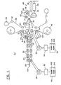
- Figure 1 illustrates a computer controlled lamination system 20 which operates on a plurality of substrates 22 as they are advanced from left to right by suitable conveyor rolls 24 which are continuously rotating.
- the rolls 24 may have an outer covering of polyurethane rubber or other suitable resilient material to have improved frictional characteristics as well as to prevent harm to the substrates 22.
- the conveyor rolls 24 are operated by means of a drive motor 26.
- a pair of opposed application rolls 28 positioned to the right of the conveyor rolls 24 are aligned with the opposed conveyor rolls and are operated by a suitable drive motor 30. It is important that the motors 26 and 30 be synchronized so that the rotational speeds of the rolls 24 and 28 are equal, a typical surface speed being in the range of approximately 1.2 to 1.8 m/mn (four to six feet per minute).
- the application rolls 28 are preferably formed of steel with an outer coating of silicon rubber or other suitable resilient material.
- squeegee rollers 31 Intermediate the application rolls 28 and the conveyor rolls 24 are a pair of similarly opposed squeegee rollers 31 between which the substrates 22 pass.
- the squeegee rollers are covered, in a fashion generally similar to the application rolls, with rubber or a rubber-like material.
- One or more pressure cylinders 31A serve to urge the squeegee rollers into engagement with the substrates at the same time that water is applied to their outer surfaces as schematically represented by a nozzle 31 B. Since either too much water or too little water will detract from the ability of the photoresist to adhere to the substrate, the pressure cylinders 31 A are operated to assure that just the correct amount of water is retained on the rollers when they engage the substrate.
- a suitable encoder/pulse generator 32 and 34 Associated with each of the drive motors 26 and 30 is, respectfully, a suitable encoder/pulse generator 32 and 34, and, in turn, a counter/preset device, 36 and 38.
- a suitable encoder/pulse generator 32 and 34 Associated with each of the drive motors 26 and 30 is, respectfully, a suitable encoder/pulse generator 32 and 34, and, in turn, a counter/preset device, 36 and 38.
- an encoder/pulse generator suitable for purposes of the invention is Type RE1-600 sold by Shimpo of Cedarhurst, New York.
- An example of a counter/preset device suitable for purposes of the invention is Model CB-126 manufactured by Dynapar of Gurnee, IL.
- a substrate 22 is advanced by the conveyor rolls 24 toward and through the preloaded squeegee rollers 31, then toward and through a nip 40 (see Figure 2A) between converging surfaces of the opposed heated application rolls 28.
- the nip 40 can be defined as that region between the opposed application rolls 28 and lying in a plane which includes the rotational axes of the rolls.
- a web of photosensitive material 42 which includes a photosensitive layer 44 coated on a polyester carrier web 46 which may be, for example, manufactured by E.I. duPont de Nemours and Company under the trademark "MYLAR" is advanced from a feed roll 48 to the nip 40 upon rotation of the application rolls 28. Specifically, the web material 42 is drawn across the heated application rolls 28 such that rotation of the application rolls serves to draw the web material from each associated feed roll.
- Each feed roll 48 is preferably provided with a drag clutch (not shown) to impart tension to the web material 42.
- An additional expedient to maintain tension of the web material 42 at a relatively constant level is a tension roll 50 (see Figure 1).
- the tension roll 50 is rotatably engagable with the web material 42, being biased thereagainst by a spring 52.
- the tension roll 50 may be rotatably mounted on a rocker arm 54 which, in turn, is pivotally mounted about an axis 56 generally parallel to the axis of rotation of the tension roll 50.
- each substrate 22 as it moves through the system 20 is detected by a series of suitable sensors 58, 60, and 62 provided at spaced locations along the path of a substrate.
- the encoder pulse generators 32, 34 associated with the respective motors generate electrical pulses and transmit these pulses to associated counter/preset devices 36, 38.
- the counter/preset devices 36, 38 are notified by the sensors when to start counting the pulses received from the encoder pulse generators. Whenever the number of the pulses received and counted reaches a preset number, the appropriate counter/preset device signals the system controller that it is time for some event to occur.
- the further operation of the sensors 58, 60, and 62, particularly in conjunction with the counter/preset devices 36, 38 will be described subsequently.
- the application rolls 28 remain withdrawn in the inactive position (figure 2A), but the drive motor 30 is activated so as to advance the web of photosensitive material 42 beyond the nip 40. This is for the reason that the photosensitive layer 44 has been positioned against the application rolls 28 for a sufficient period of time with the rolls stationary that the heat of the application rolls adversely affects the chemical makeup of the photosensitive layer 44.
- the time of the pause as well as the temperature of the application rolls 28 depends upon whether the substrates 22 are "thick” or "thin".
- a temperature of approximately 125 ° C. would be appropriate for a duration of 0.75 seconds.
- a temperature of 100°C. is appropriate for a duration of 0.33 seconds.
- a typical "foot print” would be about 6.35 mm (0.25) inches in length and is effective to cause the photosensitive layer 44 to be evenly bonded to the surface of the substrate 22.
- the motors 26 and 30 are activated, once again, to advance the substrate 22 along its path through the system 20 ( Figures 2C and 4).
- the substrate reaches a second location, still positioned between the application rolls 28 but such that a trailing edge 66 of the substrate is positioned a small distance to the left ( Figure 1) of the nip 40, only the drive motor 30 is interrupted in its operation while the application rolls 28 remain in the active position. This happens for a second predetermined period of time which may be of the same duration as the first predetermined period of time.
- the application rolls are withdrawn to the inactive position ( Figure 2D) and the drive motor 30 is again activated so as to advance the web material 42 and substrate 22 beyond the nip 40. While the application rolls 28 are stopped on the trailing edge of the substrate, as discussed above, the conveyor rolls 24 continue in operation and convey the next substrate 22 through the squeegee rollers 31 and under the sensor 60, starting operation of the counter/preset device 36. At this point, the application cycle begins for the next substrate.
- the pause of the application rolls in the active position which thereby causes pressure contact between the photosensitive layer 44 and the substrate 22 thereby defines, viewing Figure 3, a margin 72 between the leading edge 64 of the substrate and a beginning line of demarcation 74 of the photosensitive layer where it is laminated to the substrate.
- a margin 76 is defined between the trailing edge 66 of the substrate and a terminal line of demarcation 78 of the photosensitive layer where it is laminated to the substrate.
- the photosensitive layer 44 separates along the line of demarcation 74 partly by shearing and partly by elongation.
- the line of demarcation thus created is a clean one by reason of the earlier pause of the application rolls 28 in the active position which resulted in a uniform pressure and temperature being applied to the photosensitive layer 44 and to the substrate 22.
- a grip and trim unit 86 (Figure 1) which is of generally known design is effective to draw the substrate 22 toward the right ( Figure 1) after the trailing edge 66 has advanced beyond the application rolls 28.
- the grip and trim unit 86 includes upper and lower pancake members 88 and 90, respectively, which move as a unit along a track 92.
- a hydraulic cylinder 94 which extends and retracts a piston rod 96 is effective to move the pancake members 88, 90 along the track 92.
- a gripper 98 is advanced by a suitable actuator 100 to thereby grip the substrate end and draw it rightwardly upon operation of the cylinder 94. In this manner, the substrate is drawn beyond the trimming wedges 68 and is in position for a subsequent operation.
- the preset/counter device 36 has a pair of preset members in the form of decade thumbwheels 102 and 104.
- the thumbwheel 102 establishes leading edge placement. That is, it sets the encoder pulse generator 32 to count up to a predetermined number of pulses beginning when the leading edge 64 of the substrate is opposite the sensor 60. By the time the count is completed, the substrate will have advanced so that the leading edge 64 extends into, and slightly beyond the nip 40 whereupon the motors 26 and 30 temporarily terminate their operation. Immediately thereafter, the application rolls 28 are moved to their active positions.
- the thumbwheel 104 establishes for the encoder pulse generator 32 a preset number of pulses after which control is turned over to the preset/counter device 38.
- a decade thumbwheel 106 establishes the number of pulses to be counted up to by the encoder pulse generator 34 beginning when the trailing edge 66 passes the sensor 60.
- a decade thumbwheel 108 establishes the preset count to be reached after which the grip and trim unit 86 operates to draw the substrate 22 to the right after the lamination process has been completed.
- Preset counter device 38 starts the count for trailing edge grip trimming after the leading edge has blocked the sensor 62.
- the steps of the operation performed by the lamination system 20 is generally as follows, in sequence;
Description
- This invention relates to an improved process for laminating a discrete section of a photosensitive layer to at least one substrate and automatically trimming the laminated sections.
- Typical of the prior art of laminating processes in which a relatively thin layer of material is applied to a relatively thick substrate are the U.S. patents to Del Bianco, No. 4,214,936, and to Gebrian et al, No. 4,495,014 (EP-A 117 483).
- According to Del Bianco, a continuing series of panels to be laminated are advanced through successive preparatory stations before laminating occurs. Each panel is preheated by rolls which advance the panels toward the nip of rolls which actually perform the lamination step. A sensor immediately upstream of the nip of the laminating rolls senses the leading and trailing edges of a panel to cause time delayed operation of the laminating rolls. This results in a discontinuous operation with the stated desired result of uniformly spacing the resultant laminated panels from each other. As disclosed in Del Bianco, the laminating rolls remain closed at all times and rotate continuously while a panel is inserted between them. As a result, the entire length of a panel is laminated. Also, the rolls operate discontinuously. Once they start to rotate, they continue until the panel advances through and beyond them. Successive panels are loosely joined by an interconnecting length of film and no mechanism is disclosed for severing the film from the panel.
- In Gebrian et al, a board to be laminated is heated, then advanced into the open nip of a pair of pressure rolls. A web of photosensitive film which includes a photosensitive layer coated on a carrier web is advanced from a feed roll to the open nip and over each pressure roll so that the photosensitive layer faces inward toward the advancing board. The pressure rolls are brought together at a specific distance behind the leading edge of the board to form a line of pressure perpendicular to the direction of advance. The board continues to advance through the closed nip and the photosensitive layer is laminated to the board surface until a second specified distance along the board is reached, at which time, with the board still advancing, the pressure rolls are separated and returned to the open nip configuration. The photosensitive layer is trimmed from the carrier web at the locations at which the lamination respectively begins and ends on the board. Each pressure roll for applying the photosensitive film is then reversed so that the terminal edge of the photosensitive film on the carrier web is returned to the nip of the pressure rolls for lamination on a subsequent board on a further surface of the same board to thereby avoid waste.
- Another prior art laminating process is disclosed in US-A 4 025 380. Discrete section of a supported photosensitive layer are laminated to a sheet substrate by advancing the preheated substrate to and through a nip between converging surfaces of opposed application rolls and by applying a continuous length of the supported photosensitive layer to the nip. The application rolls and the substrate are stopped only for shearing the photosensitive layer into sheets which are of the size required.
- Prior Art having the general nature of the patents just described exhibit some drawbacks. For example, it often occurred that substrates operated on by prior art processes, when laminated, would exhibit a photosensitive layer having localized poor adhesion on the substrate resulting in ragged edges of the photosensitive layer along the line of demarcation at which the photosensitive layer is laminated to the substrate. In turn, small chips or flakes of the photosensitive layer then tend to break off and adhere to the surface of the laminated substrate at other locations. Such adherence at other locations will cause undesirable exposure variations during a later step which adversely affect the end product. Another drawback of prior art processes resided in the fact that they required greater spacing between successive substrates resulting in a lower production rate than desirable. This often resulted in wastage of photosensitive layer material. Since the photosensitive layer material generally continues to advance to the nip of the pressure rolls even when it extends between successive substrates, it follows that the greater the distance between successive substrates, the greater the wastage of the photosensitive layer material. Additionally, systems for performing prior art processes often lacked the ability to readily read just so as to accommodate, as desired, different sizes of substrates and different sizes of placements of the photosensitive layer.
- The invention as claimed is intended to remedy these drawbacks.
- The present invention pertains to a process for laminating discrete sections of a supported photosensitive layer onto a continuing series of sheet substrates. Each substrate is advanced to and through the nip of heated application rolls at the same time that a continuous length of the supported photosensitive layer is also supplied to the nip. When the substrate reaches a first location positioned between the application rolls, all movement ceases except that the rolls move from an inactive disengaged position toward the substrate to an active position to cause pressure contact between the photosensitive layer and the substrate to thereby laminate the photosensitive layer to the substrate. There is a pause for a predetermined period of time with the rolls in the active positions before the substrate is again advanced with the rolls still in the active positions and the photosensitive layer again supplied to the nip. When the substrate reaches a second location, all motion ceases once again and there is another pause for another predetermined period of time with the rolls in the active positions after which the rolls are withdrawn to an inactive position. During the second pause, a successive substrate continues to advance toward the preceding stationary substrate. At appropriate times, the supported photosensitive layer is trimmed from the laminated photosensitive layer. The resulting laminated substrate is provided with well defined edges of the photosensitive layer where it is firmly laminated to the substrate along lines spaced from the leading and trailing edges of the substrate. This desirably results in an unlaminated margin adjacent the leading and trailing edges of the substrate.
- There are a number of benefits which flow directly from the invention as disclosed. In a first instance, a unique feature of the invention resides in the operation of the lamination process in the course of which the application rolls are caused to pause in an active position where they cause pressure contact between the sensitive layer and the substrate for laminating the former to the latter near the leading edge and near the trailing edge of the substrate. The pause which occurs for a predetermined period of time allows pressure and temperature to become substantially more uniform across the photosensitive layer and substrate and thereby establishes a distinct "foot print". This has the result that a straighter, less ragged line of demarcation of the photosensitive layer is achieved where it adheres to the substrate.
- Another feature of the invention is that it improves the accuracy of placement of the lines of demarcation on the substrate. A concomitant benefit is the repeatability of placement of the photosensitive layer on the substrate. This is achieved because the substrate is stopped at a known location when the rolls are closed and when they are opened.
- Yet another feature of the invention is that it assures a high rate of productivity of laminated substrates by continuing to advance successive substrates during the pause at a substrate presently being laminated, and at the same time reducing waste of the photosensitive layer.
- Yet another feature is the unique method used to regulate the amount of water present on the substrate surface during lamination. Previous equipment used gravity loaded linen covered rollers to both apply and remove the excess water necessary for adhesion of the photosensitive layer. The new invention uses a set of rubber coated squeegee rolls. The correct amount of retained water is obtained by adjusting the pressure on two air cylinders which force the squeegee rollers together. The new method is superior to the previous method because of its adjustability and because the rubber coating now used never requires replacement as did the old.
- Other and further features, objects, advantages, and benefits of the invention will become apparent from the following description taken in conjunction with the following drawings. It is to be understood that the foregoing general description and the following detailed description are exemplary and explanatory but are not to be restrictive of the invention. The accompanying drawings which are incorporated in and constitute a part of this invention, illustrate one of the embodiments of the invention and, together with the description, serve to explain the principles of the invention in general terms. Like numerals refer to like parts throughout the disclosure.
- Figure 1 is a diagrammatic representation of the process of the present invention involving laminating and trimming of a photosensitive layer applied to a continuing series of substrates;
- Figures 2A, 2B, 2C and 2D are detailed side elevation views which illustrate successive steps in the laminating process of Figure 1 and, specifically, relative positions of the application rolls, substrates, and the photosensitive layer according to the Figure 1 process;
- Figure 3 is top plan view of a substrate with a photosensitive layer applied thereto according to the invention;
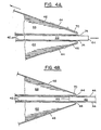
- Figure 4 is diagrammatic side elevation view of one end of a substrate to which a photosensitive layer has been applied, correlating generally to the step illustrated in Figure 2C;
- Figure 4A is a diagrammatic detail side elevation view illustrative of the trimming step performed adjacent the leading edge of the substrate; and
- Figure 4B is a diagrammatic detail side elevation view, similar to Figure 4A, and illustrating the trimming operation as it is performed adjacent the trailing edge of the substrate.
- The present invention has been conceived and reduced to practice in order to satisfy recent requirements of the end product design. In this regard, an improved capability was sought for placing a photosensitive layer, sometimes referred to as "photo resist", on a copper-epoxy/glass substrate in a manner assuring a margin around the periphery of the substrate which is free of the photo resist. Furthermore, it was determined necessary to precisely control the magnitude of the margin while minimizing resist waste, obtain a flake free resist edge, and easily adjust the relative placement of the resist on the substrate and/or the magnitude of the margin. To this end, known processes have been modified and, as disclosed herein, have resulted in a markedly improved end product.
- Turn now to the drawings, and initially to Figure 1, which illustrates a computer controlled
lamination system 20 which operates on a plurality ofsubstrates 22 as they are advanced from left to right by suitable conveyor rolls 24 which are continuously rotating. Therolls 24 may have an outer covering of polyurethane rubber or other suitable resilient material to have improved frictional characteristics as well as to prevent harm to thesubstrates 22. - The conveyor rolls 24 are operated by means of a
drive motor 26. A pair of opposed application rolls 28 positioned to the right of the conveyor rolls 24 are aligned with the opposed conveyor rolls and are operated by asuitable drive motor 30. It is important that themotors rolls - Intermediate the application rolls 28 and the conveyor rolls 24 are a pair of similarly opposed
squeegee rollers 31 between which thesubstrates 22 pass. The squeegee rollers are covered, in a fashion generally similar to the application rolls, with rubber or a rubber-like material. One or more pressure cylinders 31A serve to urge the squeegee rollers into engagement with the substrates at the same time that water is applied to their outer surfaces as schematically represented by anozzle 31 B. Since either too much water or too little water will detract from the ability of the photoresist to adhere to the substrate, the pressure cylinders 31 A are operated to assure that just the correct amount of water is retained on the rollers when they engage the substrate. - Associated with each of the
drive motors pulse generator - In the course of operation of the
system 20, asubstrate 22 is advanced by the conveyor rolls 24 toward and through thepreloaded squeegee rollers 31, then toward and through a nip 40 (see Figure 2A) between converging surfaces of the opposed heated application rolls 28. The nip 40 can be defined as that region between the opposed application rolls 28 and lying in a plane which includes the rotational axes of the rolls. - A web of
photosensitive material 42 which includes aphotosensitive layer 44 coated on apolyester carrier web 46 which may be, for example, manufactured by E.I. duPont de Nemours and Company under the trademark "MYLAR" is advanced from afeed roll 48 to the nip 40 upon rotation of the application rolls 28. Specifically, theweb material 42 is drawn across the heated application rolls 28 such that rotation of the application rolls serves to draw the web material from each associated feed roll. Eachfeed roll 48 is preferably provided with a drag clutch (not shown) to impart tension to theweb material 42. An additional expedient to maintain tension of theweb material 42 at a relatively constant level is a tension roll 50 (see Figure 1). Thetension roll 50 is rotatably engagable with theweb material 42, being biased thereagainst by aspring 52. Thetension roll 50 may be rotatably mounted on arocker arm 54 which, in turn, is pivotally mounted about anaxis 56 generally parallel to the axis of rotation of thetension roll 50. - Movement of each
substrate 22 as it moves through thesystem 20 is detected by a series ofsuitable sensors system 20, whenever thedrive motor 26 is operated to rotate the conveyor rolls 24 or thedrive motor 30 is operated to drive the applicator rolls 28, theencoder pulse generators preset devices preset devices sensors preset devices - As the leading edge of a first of a continuing series of
substrates 22 passes thesensor 58, the application rolls 28 remain withdrawn in the inactive position (figure 2A), but thedrive motor 30 is activated so as to advance the web ofphotosensitive material 42 beyond thenip 40. This is for the reason that thephotosensitive layer 44 has been positioned against the application rolls 28 for a sufficient period of time with the rolls stationary that the heat of the application rolls adversely affects the chemical makeup of thephotosensitive layer 44. The rotation of the application rolls 28, when they are thus withdrawn to the inactive disengaged position, thereby assures that the affectedphotosensitive layer 44 Mill not be applied to asubsequent substrate 22. - When a
substrate 22 is properly positioned so that a leading edge 64 (Figure 3) extends a short distance beyond thenip 40, thedrive motors substrate 22 to an active position (Figure 2B). This occurs to cause pressure contact between thephotosensitive layers 42 and the substrate whereby the photosensitive layer is laminated to the substrate. With the application rolls 28 thereby in the active position, thedrive motors - The time of the pause as well as the temperature of the application rolls 28 depends upon whether the
substrates 22 are "thick" or "thin". For example, in the instance of a "thick" substrate, that is, a copper coated epoxy substrate having a total thickness within the range of 0.8 and 1.15 mm (0.035 and 0.045 inches), a temperature of approximately 125°C. would be appropriate for a duration of 0.75 seconds. In the instance of a "thin" substrate, that is, one whose thickness lies in the range of 0.17 to 0.33 mm (0.007 to 0.013 inches) of copper coating on epoxy, a temperature of 100°C. is appropriate for a duration of 0.33 seconds. It is noteworthy that a typical "foot print" would be about 6.35 mm (0.25) inches in length and is effective to cause thephotosensitive layer 44 to be evenly bonded to the surface of thesubstrate 22. - After the first predetermined period of time with the application rolls 28 in the active position has passed, the
motors substrate 22 along its path through the system 20 (Figures 2C and 4). When the substrate reaches a second location, still positioned between the application rolls 28 but such that a trailingedge 66 of the substrate is positioned a small distance to the left (Figure 1) of thenip 40, only thedrive motor 30 is interrupted in its operation while the application rolls 28 remain in the active position. This happens for a second predetermined period of time which may be of the same duration as the first predetermined period of time. - Thereafter, the application rolls are withdrawn to the inactive position (Figure 2D) and the
drive motor 30 is again activated so as to advance theweb material 42 andsubstrate 22 beyond thenip 40. While the application rolls 28 are stopped on the trailing edge of the substrate, as discussed above, the conveyor rolls 24 continue in operation and convey thenext substrate 22 through thesqueegee rollers 31 and under the sensor 60, starting operation of the counter/preset device 36. At this point, the application cycle begins for the next substrate. - The pause of the application rolls in the active position which thereby causes pressure contact between the
photosensitive layer 44 and thesubstrate 22 thereby defines, viewing Figure 3, amargin 72 between theleading edge 64 of the substrate and a beginning line ofdemarcation 74 of the photosensitive layer where it is laminated to the substrate. Similarly, amargin 76 is defined between the trailingedge 66 of the substrate and a terminal line ofdemarcation 78 of the photosensitive layer where it is laminated to the substrate. - With continuing reference to Figure 1, it is seen that after the
leading edge 64 of asubstrate 22 passes beyond the application rolls 28, it advances between a pair of opposed trimmingwedges 68, each of which terminates at an apex 70 at its end farthest from the application rolls 28. As thesubstrate 22 continues to be advanced by the application rolls 28, it eventually reaches a position at which the line ofdemarcation 74 is generally coextensive with the apex 70 of an associated trimming wedge 68 (Figure 4A). At this location, thecarrier web 46 abruptly reverses direction to pass over a pair ofguide rollers 80 and 82 (Figure 1) and then onto atakeup roll 84. As thecarrier web 46 abruptly reverses direction at the apex 70, thephotosensitive layer 44 separates along the line ofdemarcation 74 partly by shearing and partly by elongation. In any event, the line of demarcation thus created is a clean one by reason of the earlier pause of the application rolls 28 in the active position which resulted in a uniform pressure and temperature being applied to thephotosensitive layer 44 and to thesubstrate 22. - In a similar fashion, when the substrate is moved to the location at which the terminal line of
demarcation 78 is slightly previous to being coextensive with the apex 70 (Figure 4B), a grip and trim unit 86 (Figure 1) which is of generally known design is effective to draw thesubstrate 22 toward the right (Figure 1) after the trailingedge 66 has advanced beyond the application rolls 28. This movement causes that portion of thephotosensitive layer 44 adjacent the terminal line ofdemarcation 78 but not bonded to thesubstrate 22 to yield and break at its stressed location which is along the terminal line ofdemarcation 78. The grip andtrim unit 86 includes upper andlower pancake members hydraulic cylinder 94 which extends and retracts apiston rod 96 is effective to move thepancake members substrate 22 is moved to a position such that themargin 78 is just about to exit thewedge apex 70, agripper 98 is advanced by asuitable actuator 100 to thereby grip the substrate end and draw it rightwardly upon operation of thecylinder 94. In this manner, the substrate is drawn beyond the trimmingwedges 68 and is in position for a subsequent operation. - The operative relationship of the
sensors counters counter devices counter device 36 has a pair of preset members in the form ofdecade thumbwheels thumbwheel 102 establishes leading edge placement. That is, it sets theencoder pulse generator 32 to count up to a predetermined number of pulses beginning when the leadingedge 64 of the substrate is opposite the sensor 60. By the time the count is completed, the substrate will have advanced so that the leadingedge 64 extends into, and slightly beyond thenip 40 whereupon themotors - The
thumbwheel 104 establishes for the encoder pulse generator 32 a preset number of pulses after which control is turned over to the preset/counter device 38. With respect to the preset/counter device 38, adecade thumbwheel 106 establishes the number of pulses to be counted up to by theencoder pulse generator 34 beginning when the trailingedge 66 passes the sensor 60. When the preset total is reached, the application rolls 28 open to their inactive positions. Similarly, adecade thumbwheel 108 establishes the preset count to be reached after which the grip andtrim unit 86 operates to draw thesubstrate 22 to the right after the lamination process has been completed. Presetcounter device 38 starts the count for trailing edge grip trimming after the leading edge has blocked thesensor 62. - The steps of the operation performed by the
lamination system 20 is generally as follows, in sequence; -
- 1. Leading
edge 64 offirst substrate 22reaches sensor 58; burnt photosensitive layer is advanced by application rolls 28. - 2. Leading edge of
first substrate 22 passes sensor 60; starts roll close count of input conveyor pulses. - 3. Both
motors nip 40. - 4. Application rolls 28 close; begin appropriate time delay.
- 5.
Motors - 6. Leading edge trim operation occurs.
- 7. Leading edge of first substrate passes
sensor 62; start trailing edge trim count of application roll pulses. - 8. Trailing
edge 66 of first substrate positioned opposite sensor 60; application roll open count of application roll pulses begins. - 9. Leading edge of second substrate passes
sensor 58; there is no effect. - 10. Only motor 30 stops; trailing edge of first substrate slightly before nip 40 (e.g. approx. 6.35 mm (0.25 inches); time delay begins.
- 11. Leading edge of second substrate passes sensor 60; application roll close count of input conveyor pulses begins.
- 12. Application rolls open after the pause of the trailing edge of the first substrate.
- 13.
Motor 30 starts; first panel continues to advance. - 14. Trailing edge trim performed on first substrate;
motors - 15. Application rolls close on second panel; start appropriate time delay.
- 16.
Motors - 17. Trailing edge of first substrate is grip trimmed.
- 18. Continue from step number 9 on a third substrate.
- Thus has been disclosed an improved process of laminating a discrete section of a photosensitive layer to a substrate and automatically trimming the laminated sections. The positioning of the laminations on the substrate is adjustable; the lines of demarcation of the laminations are sharp and well defined; and the process results in a higher rate of production than previously with reduced waste of the photosensitive layer material.
Claims (12)
Applications Claiming Priority (2)
| Application Number | Priority Date | Filing Date | Title |
|---|---|---|---|
| US917716 | 1986-10-10 | ||
| US06/917,716 US4714504A (en) | 1986-10-10 | 1986-10-10 | Process of laminating a photosensitive layer of a substrate |
Publications (3)
| Publication Number | Publication Date |
|---|---|
| EP0263273A2 EP0263273A2 (en) | 1988-04-13 |
| EP0263273A3 EP0263273A3 (en) | 1989-01-04 |
| EP0263273B1 true EP0263273B1 (en) | 1990-11-14 |
Family
ID=25439226
Family Applications (1)
| Application Number | Title | Priority Date | Filing Date |
|---|---|---|---|
| EP87111965A Expired - Lifetime EP0263273B1 (en) | 1986-10-10 | 1987-08-18 | Process of laminating |
Country Status (7)
| Country | Link |
|---|---|
| US (1) | US4714504A (en) |
| EP (1) | EP0263273B1 (en) |
| JP (1) | JPH0727214B2 (en) |
| BR (1) | BR8704474A (en) |
| CA (1) | CA1284938C (en) |
| DE (1) | DE3766216D1 (en) |
| ES (1) | ES2018515B3 (en) |
Families Citing this family (23)
| Publication number | Priority date | Publication date | Assignee | Title |
|---|---|---|---|---|
| US4834821A (en) * | 1988-01-11 | 1989-05-30 | Morton Thiokol, Inc. | Process for preparing polymeric materials for application to printed circuits |
| US4946524A (en) * | 1989-03-02 | 1990-08-07 | Morton International, Inc. | Applicator and method for applying dry film solder mask on a board |
| JPH0651360B2 (en) * | 1989-06-04 | 1994-07-06 | ソマール株式会社 | Method and device for attaching thin film |
| JPH037343A (en) * | 1989-06-04 | 1991-01-14 | Somar Corp | Thin film guiding device for adhering thin film |
| US5160399A (en) * | 1989-09-25 | 1992-11-03 | Canon Kabushiki Kaisha | Laminating apparatus |
| JPH03147833A (en) * | 1989-11-04 | 1991-06-24 | Somar Corp | Method for sticking thin film and executing device thereof |
| US5306381A (en) * | 1990-06-11 | 1994-04-26 | Canon Kabushiki Kaisha | Laminating apparatus |
| US5106450A (en) * | 1990-12-20 | 1992-04-21 | International Business Machines Corporation | Dry film resist transport and lamination system for semiconductor wafers |
| US5328546A (en) * | 1992-04-03 | 1994-07-12 | International Business Machines Corp. | Photo resist film application mechanism |
| US5304275A (en) * | 1993-03-03 | 1994-04-19 | E-Z Machine Corp. | Applying a reinforcement film to sheets |
| US5372670A (en) * | 1994-02-02 | 1994-12-13 | International Business Machines Corporation | System for wet application of a dry film to a panel |
| IT1273910B (en) * | 1994-08-05 | 1997-07-11 | Breton Automazioni Spa | AUTOMATIC EQUIPMENT FOR THE APPLICATION OF A SELF-ADHESIVE PROTECTION FILM TO STONE SLABS LEAVING FROM AN OPERATING MACHINE FOR THEIR SURFACE TREATMENT |
| DE69521112T2 (en) * | 1994-12-27 | 2002-03-21 | Toyoda Gosei Kk | Process for decorating extruded rubber bodies |
| US5788802A (en) * | 1996-10-22 | 1998-08-04 | Preco Industries, Inc. | Vacuum drum feed and alignment apparatus for multiple layer laminator |
| US6615890B1 (en) * | 2000-06-09 | 2003-09-09 | Venture Tape Corp. | Tape applicator for glazing applications |
| JP2002166476A (en) * | 2000-11-30 | 2002-06-11 | Canon Inc | Laminating apparatus and method for manufacturing laminated product |
| US6732780B1 (en) * | 2002-10-25 | 2004-05-11 | Hewlett-Packard Development Company, L.P. | Print media coating device |
| JP2004333616A (en) * | 2003-05-01 | 2004-11-25 | Fuji Photo Film Co Ltd | Apparatus and method for transferring photosensitive resin |
| US7201202B2 (en) * | 2003-06-13 | 2007-04-10 | Xyron, Inc. | No-mask sticker maker |
| US7021355B2 (en) * | 2004-01-30 | 2006-04-04 | Primera Technology, Inc. | Disc tray error system |
| US20070144679A1 (en) * | 2004-06-10 | 2007-06-28 | Xyron, Inc. | No-mask sticker maker |
| WO2013021400A1 (en) * | 2011-08-05 | 2013-02-14 | Automatic Lamination Technologies S.R.L. | Panel lamination apparatus and method |
| KR102029695B1 (en) * | 2016-04-04 | 2019-11-08 | 주식회사 엘지화학 | System for laminating an optical film and Method for manufacturing a display unit using the same |
Family Cites Families (15)
| Publication number | Priority date | Publication date | Assignee | Title |
|---|---|---|---|---|
| US3623933A (en) * | 1966-07-05 | 1971-11-30 | Gen Binding Corp | Laminator |
| US3658629A (en) * | 1970-02-27 | 1972-04-25 | Ibm | Photopolymer resist sheet laminator |
| US4025380A (en) * | 1975-07-24 | 1977-05-24 | International Business Machines Corporation | Variable resist laminator |
| US4214936A (en) * | 1978-10-24 | 1980-07-29 | E. I. Du Pont De Nemours And Company | Lamination process |
| US4248655A (en) * | 1979-06-01 | 1981-02-03 | The Meyercord Co. | Position control system for a moving web |
| US4405394A (en) * | 1980-05-27 | 1983-09-20 | E. I. Du Pont De Nemours And Company | Laminating process |
| US4293635A (en) * | 1980-05-27 | 1981-10-06 | E. I. Du Pont De Nemours And Company | Photopolymerizable composition with polymeric binder |
| ZA813494B (en) * | 1980-05-27 | 1983-01-26 | Du Pont | Integrated laminating process |
| US4378264A (en) * | 1980-05-27 | 1983-03-29 | E. I. Du Pont De Nemours And Company | Integrated laminating process |
| US4338152A (en) * | 1981-02-17 | 1982-07-06 | E. I. Du Pont De Nemours And Company | Gripping arrangement for an apparatus for automatically laminating circuit boards |
| JPS57186390A (en) * | 1981-05-11 | 1982-11-16 | Asahi Chemical Ind | Method and device for laminating photosensitive dry film resist for producing printed circuit board |
| US4491492A (en) * | 1982-10-28 | 1985-01-01 | At&T Technologies, Inc. | Methods of and apparatus for applying a sheet to a rigid board |
| US4495014A (en) * | 1983-02-18 | 1985-01-22 | E. I. Du Pont De Nemours And Company | Laminating and trimming process |
| DE3307057C2 (en) * | 1983-03-01 | 1991-02-14 | Held, Kurt, 7218 Trossingen | Device for the continuous production of copper-clad electrical laminates |
| JPS6071229A (en) * | 1983-09-29 | 1985-04-23 | Somar Corp | Automatic laminator |
-
1986
- 1986-10-10 US US06/917,716 patent/US4714504A/en not_active Expired - Fee Related
-
1987
- 1987-05-29 JP JP62132012A patent/JPH0727214B2/en not_active Expired - Lifetime
- 1987-08-18 ES ES87111965T patent/ES2018515B3/en not_active Expired - Lifetime
- 1987-08-18 DE DE8787111965T patent/DE3766216D1/en not_active Expired - Fee Related
- 1987-08-18 EP EP87111965A patent/EP0263273B1/en not_active Expired - Lifetime
- 1987-08-31 BR BR8704474A patent/BR8704474A/en not_active IP Right Cessation
- 1987-09-24 CA CA000547683A patent/CA1284938C/en not_active Expired - Fee Related
Also Published As
| Publication number | Publication date |
|---|---|
| CA1284938C (en) | 1991-06-18 |
| US4714504A (en) | 1987-12-22 |
| JPS6398654A (en) | 1988-04-30 |
| EP0263273A2 (en) | 1988-04-13 |
| DE3766216D1 (en) | 1990-12-20 |
| EP0263273A3 (en) | 1989-01-04 |
| ES2018515B3 (en) | 1991-04-16 |
| JPH0727214B2 (en) | 1995-03-29 |
| BR8704474A (en) | 1988-05-24 |
Similar Documents
| Publication | Publication Date | Title |
|---|---|---|
| EP0263273B1 (en) | Process of laminating | |
| US5482593A (en) | High speed applicator for adhesive tape | |
| JP3113701B2 (en) | Hot rotary stamping apparatus and method for stamping metal foil | |
| US5431767A (en) | Apparatus for applying adhesive tape | |
| EP0744286B1 (en) | Film applying method and apparatus for carrying out the same | |
| EP0010869A1 (en) | Method and apparatus for forming a zero tail length splice between an expiring roll of web material and a new roll of the material | |
| US4961808A (en) | High lamination speed automatic laminator | |
| US4519865A (en) | Device for two-sided application of foils or similar material onto plate-shaped workpieces, and method of operating the same | |
| CA2234133A1 (en) | High speed web machine | |
| US4726865A (en) | Limp label application process | |
| US9493321B2 (en) | Method and device for adhering an edge of a laminar object | |
| KR100347857B1 (en) | Method for laminating printed circuit board and apparatus thereof | |
| JP4421787B2 (en) | Hot stamping method and hot stamping apparatus | |
| JP2772938B2 (en) | Method and apparatus for transferring pressure-sensitive adhesive layer of double-sided pressure-sensitive adhesive tape | |
| JPH0450186B2 (en) | ||
| JP2617559B2 (en) | Ultra-thin plate cutting and winding device | |
| JP3954401B2 (en) | Laminator | |
| JP3990803B2 (en) | Film sticking method | |
| KR200346636Y1 (en) | Apparatus for Laminating Green Sheet | |
| JPH0748056A (en) | Taking-up of nonadhesive tape | |
| JPS59156455A (en) | Adhesive coating method and apparatus therefor | |
| JPS6085927A (en) | Adhering method of film sheet to panel and laminator to be used therefor | |
| JPH0156188B2 (en) | ||
| JPS63175090A (en) | Production of double-sided adhesive tape and apparatus therefor | |
| CN117601552A (en) | Compression roller-free stripping device and stripping method for polyurethane foam product |
Legal Events
| Date | Code | Title | Description |
|---|---|---|---|
| PUAI | Public reference made under article 153(3) epc to a published international application that has entered the european phase |
Free format text: ORIGINAL CODE: 0009012 |
|
| AK | Designated contracting states |
Kind code of ref document: A2 Designated state(s): CH DE ES FR GB IT LI NL SE |
|
| 17P | Request for examination filed |
Effective date: 19880823 |
|
| PUAL | Search report despatched |
Free format text: ORIGINAL CODE: 0009013 |
|
| AK | Designated contracting states |
Kind code of ref document: A3 Designated state(s): CH DE ES FR GB IT LI NL SE |
|
| RHK1 | Main classification (correction) |
Ipc: B29C 67/18 |
|
| 17Q | First examination report despatched |
Effective date: 19890607 |
|
| GRAA | (expected) grant |
Free format text: ORIGINAL CODE: 0009210 |
|
| AK | Designated contracting states |
Kind code of ref document: B1 Designated state(s): CH DE ES FR GB IT LI NL SE |
|
| REF | Corresponds to: |
Ref document number: 3766216 Country of ref document: DE Date of ref document: 19901220 |
|
| ET | Fr: translation filed | ||
| ITF | It: translation for a ep patent filed |
Owner name: IBM - DR. ALFREDO BRAVI |
|
| ITTA | It: last paid annual fee | ||
| PLBE | No opposition filed within time limit |
Free format text: ORIGINAL CODE: 0009261 |
|
| STAA | Information on the status of an ep patent application or granted ep patent |
Free format text: STATUS: NO OPPOSITION FILED WITHIN TIME LIMIT |
|
| 26N | No opposition filed | ||
| EAL | Se: european patent in force in sweden |
Ref document number: 87111965.7 |
|
| PGFP | Annual fee paid to national office [announced via postgrant information from national office to epo] |
Ref country code: GB Payment date: 19950726 Year of fee payment: 9 |
|
| PGFP | Annual fee paid to national office [announced via postgrant information from national office to epo] |
Ref country code: SE Payment date: 19950804 Year of fee payment: 9 |
|
| PGFP | Annual fee paid to national office [announced via postgrant information from national office to epo] |
Ref country code: FR Payment date: 19950807 Year of fee payment: 9 |
|
| PGFP | Annual fee paid to national office [announced via postgrant information from national office to epo] |
Ref country code: ES Payment date: 19950818 Year of fee payment: 9 |
|
| PGFP | Annual fee paid to national office [announced via postgrant information from national office to epo] |
Ref country code: DE Payment date: 19950821 Year of fee payment: 9 |
|
| PGFP | Annual fee paid to national office [announced via postgrant information from national office to epo] |
Ref country code: NL Payment date: 19950830 Year of fee payment: 9 |
|
| PGFP | Annual fee paid to national office [announced via postgrant information from national office to epo] |
Ref country code: CH Payment date: 19951128 Year of fee payment: 9 |
|
| PG25 | Lapsed in a contracting state [announced via postgrant information from national office to epo] |
Ref country code: GB Effective date: 19960818 |
|
| PG25 | Lapsed in a contracting state [announced via postgrant information from national office to epo] |
Ref country code: SE Effective date: 19960819 Ref country code: ES Free format text: LAPSE BECAUSE OF EXPIRATION OF PROTECTION Effective date: 19960819 |
|
| PG25 | Lapsed in a contracting state [announced via postgrant information from national office to epo] |
Ref country code: LI Effective date: 19960831 Ref country code: CH Effective date: 19960831 |
|
| PG25 | Lapsed in a contracting state [announced via postgrant information from national office to epo] |
Ref country code: NL Effective date: 19970301 |
|
| GBPC | Gb: european patent ceased through non-payment of renewal fee |
Effective date: 19960818 |
|
| REG | Reference to a national code |
Ref country code: CH Ref legal event code: PL |
|
| PG25 | Lapsed in a contracting state [announced via postgrant information from national office to epo] |
Ref country code: FR Effective date: 19970430 |
|
| NLV4 | Nl: lapsed or anulled due to non-payment of the annual fee |
Effective date: 19970301 |
|
| PG25 | Lapsed in a contracting state [announced via postgrant information from national office to epo] |
Ref country code: DE Effective date: 19970501 |
|
| EUG | Se: european patent has lapsed |
Ref document number: 87111965.7 |
|
| REG | Reference to a national code |
Ref country code: FR Ref legal event code: ST |
|
| REG | Reference to a national code |
Ref country code: ES Ref legal event code: FD2A Effective date: 19990601 |
|
| PG25 | Lapsed in a contracting state [announced via postgrant information from national office to epo] |
Ref country code: IT Free format text: LAPSE BECAUSE OF NON-PAYMENT OF DUE FEES;WARNING: LAPSES OF ITALIAN PATENTS WITH EFFECTIVE DATE BEFORE 2007 MAY HAVE OCCURRED AT ANY TIME BEFORE 2007. THE CORRECT EFFECTIVE DATE MAY BE DIFFERENT FROM THE ONE RECORDED. Effective date: 20050818 |