EP0263260A1 - Coaxial torque sensor - Google Patents
Coaxial torque sensor Download PDFInfo
- Publication number
- EP0263260A1 EP0263260A1 EP87111460A EP87111460A EP0263260A1 EP 0263260 A1 EP0263260 A1 EP 0263260A1 EP 87111460 A EP87111460 A EP 87111460A EP 87111460 A EP87111460 A EP 87111460A EP 0263260 A1 EP0263260 A1 EP 0263260A1
- Authority
- EP
- European Patent Office
- Prior art keywords
- torque sensor
- windings
- primary
- strips
- shaft axis
- Prior art date
- Legal status (The legal status is an assumption and is not a legal conclusion. Google has not performed a legal analysis and makes no representation as to the accuracy of the status listed.)
- Withdrawn
Links
Images
Classifications
-
- G—PHYSICS
- G01—MEASURING; TESTING
- G01L—MEASURING FORCE, STRESS, TORQUE, WORK, MECHANICAL POWER, MECHANICAL EFFICIENCY, OR FLUID PRESSURE
- G01L3/00—Measuring torque, work, mechanical power, or mechanical efficiency, in general
- G01L3/02—Rotary-transmission dynamometers
- G01L3/04—Rotary-transmission dynamometers wherein the torque-transmitting element comprises a torsionally-flexible shaft
- G01L3/10—Rotary-transmission dynamometers wherein the torque-transmitting element comprises a torsionally-flexible shaft involving electric or magnetic means for indicating
- G01L3/101—Rotary-transmission dynamometers wherein the torque-transmitting element comprises a torsionally-flexible shaft involving electric or magnetic means for indicating involving magnetic or electromagnetic means
- G01L3/102—Rotary-transmission dynamometers wherein the torque-transmitting element comprises a torsionally-flexible shaft involving electric or magnetic means for indicating involving magnetic or electromagnetic means involving magnetostrictive means
Definitions
- the invention relates to a coaxial torque sensor, in which at least two strips of soft magnetic material are wound side by side around the circumference of a shaft, in which the strips each have a soft magnetic preferred direction, which run in opposite directions at an angle between 0 and 90 ° to the shaft axis and in which the strips are surrounded by at least one primary winding and one secondary winding each.
- Torque sensors of this type are known, for example, from the journal IEEE TRANSACTIONS ON MAGNETICS, Vol. Mag. 20, September 1984, pages 942 to 947 and 951 to 953.
- strips of amorphous material are glued to the circumference of the shaft at a distance from one another and at an angle of 45 ° to a shaft axis.
- the shaft is concentrically surrounded by an excitation coil and two secondary coils.
- the voltages generated in the secondary coils can be compared and evaluated, for example, in a bridge circuit. This creates a signal that is largely proportional to the torque to which the shaft in question is exposed.
- This signal is torque dependent because it causes the shaft and the associated stripes to deform and because the magnetic properties of such ferromagnetic materials change when subjected to mechanical stress.
- a magnetoelastic torque transmitter in which a measuring sleeve is applied to a shaft, which have parallel slots in two parallel, annular zones at different angles to the shaft axis. These zones of the measuring sleeves have a magnetic preferred direction, which cause different voltage states and thus different magnetic behavior due to a torque acting in the shaft.
- each magnetic zone is surrounded by a secondary winding and each secondary winding is in turn surrounded by a primary winding.
- the object of the present invention is to provide an arrangement in which falsification of the measurement signal is largely prevented by a displacement of the shaft within the windings surrounding it.
- width of the strips in the direction of the shaft axis is at least twice as large as the width of the associated secondary windings in the same direction, and that the secondary windings are adjusted so that they surround the central part of the associated strip.
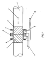
- a shaft 1 with the shaft axis 2 is surrounded by two strips 3 and 4. These strips are made of soft magnetic - preferably amorphous - material and have a preferred magnetic direction, which is indicated by the direction of hatching within strips 3 and 4 and which preferably extends at an angle of 45 ° to the direction of shaft axis 2. It is surrounded Shaft 1 from a bobbin 5, which - seen in the direction of the shaft axis 2 - carries two secondary windings 6 and 7 on the outside and a primary winding 8 in the middle. The primary winding 8 is connected to an AC voltage source 9 and the secondary windings are connected in series with one another and connected to measuring terminals 10 at which the output signal is present.
- the arrangement of primary and secondary windings means that the secondary windings 6 and 7 need only have a small width in the direction of the shaft axis 2, so that the ratio of the width of the strips 3 and 4 to the width of the windings 6 and 7 is slightly relative can be made big.
- the arrangement of the primary winding 8 in the direction of the shaft axis 2 next to - here between - the secondary windings 6 and 7 gives the advantage that - regardless of the outer diameter of the secondary windings - the primary winding is close to the shaft 1, so that the lowest possible energy is necessary to ensure sufficient flooding of strips 3 and 4.
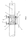
- the embodiment of Figure 2 has the advantage over the arrangement of Figure 1 that the magnetic circuits of the secondary windings 6 and 7 are largely decoupled from each other by the distance d3 of the secondary windings 6 and 7 and strips 3 and 4.
- the width d4 of strips 3 and 4 is again large the corresponding width of the secondary windings 6 and 7.
- the inner spacing of the strips 3 and 4 from each other is denoted by d 1 and should be greater, the more soft magnetic the material of the shaft 1 is.
- the shaft 1 moves relative to the bobbin 5 in the direction of the shaft axis 2, not only will the secondary windings remain largely in the central region of the strips 3 and 4, but also that produced by the primary winding 11 and that by the primary winding 12 Magnetic field influenced by the displacement in the same sense, so that there is a reduced sensitivity of the torque sensor to displacements of the shaft 1 and the bobbin 5 compared to the embodiment of Figure 1.
- a further reduction in sensitivity to displacements of the shaft 1 can be achieved by shielding the coil body 5 at the end, since these limit the expansion of the magnetic field generated by the primary windings in the direction of the shaft axis and thus reduce the influence of the outer edges of the strips 3 and 4 .
Landscapes
- Physics & Mathematics (AREA)
- Electromagnetism (AREA)
- General Physics & Mathematics (AREA)
- Measurement Of Length, Angles, Or The Like Using Electric Or Magnetic Means (AREA)
- Transmission And Conversion Of Sensor Element Output (AREA)
Abstract
Description
Die Erfindung betrifft einen koaxialen Drehmomentsensor, bei dem mindestens zwei Streifen aus weichmagnetischem Material nebeneinander um den Umfang einer Welle gewickelt sind, bei dem die Streifen je eine weichmagnetische Vorzugsrichtung haben, die gegensinnig in einem Winkel zwischen 0 und 90° zur Wellenachse verlaufen und bei dem die Streifen von mindestens einer Primärwicklung und je einer Sekundärwicklung umgeben sind.The invention relates to a coaxial torque sensor, in which at least two strips of soft magnetic material are wound side by side around the circumference of a shaft, in which the strips each have a soft magnetic preferred direction, which run in opposite directions at an angle between 0 and 90 ° to the shaft axis and in which the strips are surrounded by at least one primary winding and one secondary winding each.
Derartige Drehmomentsensoren sind beispielsweise aus der Zeitschrift IEEE TRANSACTIONS ON MAGNETICS, Vol. Mag. 20, September 1984, Seiten 942 bis 947 und 951 bis 953 bekannt. Hier werden Streifen von amorphem Material mit Abstand zueinander und mit einem Winkel von 45° zu einer Wellenachse auf den Umfang der Welle geklebt. Die Welle ist von einer Erregungs- und zwei Sekundärspulen konzentrisch umgeben. Die in den Sekundärspulen erzeugten Spannungen können beispielsweise in einer Brückenschaltung verglichen und ausgewertet werden. Dadurch entsteht ein Signal, das weitgehend proportional dem Drehmoment ist, dem die betreffende Welle ausgesetzt wird. Dieses Signal ist vom Drehmoment abhängig, da dies eine Verformung der Welle und der damit verbundenen Streifen bewirkt und da sich die magnetischen Eigenschaften derartiger ferromagnetischer Materialien ändern, wenn sie einer mechanischen Spannung ausgesetzt werden.Torque sensors of this type are known, for example, from the journal IEEE TRANSACTIONS ON MAGNETICS, Vol. Mag. 20, September 1984, pages 942 to 947 and 951 to 953. Here strips of amorphous material are glued to the circumference of the shaft at a distance from one another and at an angle of 45 ° to a shaft axis. The shaft is concentrically surrounded by an excitation coil and two secondary coils. The voltages generated in the secondary coils can be compared and evaluated, for example, in a bridge circuit. This creates a signal that is largely proportional to the torque to which the shaft in question is exposed. This signal is torque dependent because it causes the shaft and the associated stripes to deform and because the magnetic properties of such ferromagnetic materials change when subjected to mechanical stress.
Weiterhin ist aus der DE-OS 33 19 449 ein magnetoelastischer Drehmomentgeber bekannt, bei dem auf eine Welle eine Meßhülse aufgebracht ist, die in zwei parallelen, ringförmigen Zonen in unterschiedlichem Winkel zur Wellenachse parallele Schlitze aufweisen. Diese Zonen der Meßhülsen besitzen eine magnetische Vorzugsrichtung, die durch ein in der Welle wirkendes Drehmoment unterschiedliche Spannungszustände und damit ein unterschiedliches magnetisches Verhalten bewirken. Um ein Meßsignal zu erzeugen, ist jede magnetische Zone von einer Sekundärwicklung und jede Sekundärwicklung wiederum von einer Primärwicklung umgeben.Furthermore, from DE-OS 33 19 449 a magnetoelastic torque transmitter is known, in which a measuring sleeve is applied to a shaft, which have parallel slots in two parallel, annular zones at different angles to the shaft axis. These zones of the measuring sleeves have a magnetic preferred direction, which cause different voltage states and thus different magnetic behavior due to a torque acting in the shaft. In order to generate a measurement signal, each magnetic zone is surrounded by a secondary winding and each secondary winding is in turn surrounded by a primary winding.
Aufgabe der vorliegenden Erfindung ist es, eine Anordnung anzugeben, bei der eine Verfälschung des Meßsignals durch eine Verschiebung der Welle innerhalb der sie umgebenden Wicklungen weitgehend verhindert wird.The object of the present invention is to provide an arrangement in which falsification of the measurement signal is largely prevented by a displacement of the shaft within the windings surrounding it.
Diese Aufgabe wird erfindungsgemäß dadurch gelöst, daß die Breite der Streifen in Richtung der Wellenachse mindestens doppelt so groß ist, wie die Breite der zugehörigen Sekundärwicklungen in gleicher Richtung, und daß die Sekundärwicklungen so justiert sind, daß sie den mittleren Teil des zugehörigen Streifens umgeben.This object is achieved in that the width of the strips in the direction of the shaft axis is at least twice as large as the width of the associated secondary windings in the same direction, and that the secondary windings are adjusted so that they surround the central part of the associated strip.
Zwei Ausführungsbeispiele der Erfindung sind anhand der Figuren 1 und 2 beschrieben.Two embodiments of the invention are described with reference to Figures 1 and 2.
In Figur 1 ist eine Welle 1 mit der Wellenachse 2 von zwei Streifen 3 und 4 umgeben. Diese Streifen bestehen aus weichmagnetischem - vorzugsweise amorphem - Material und besitzen eine magnetische Vorzugsrichtung, die durch die Richtung der Schraffur innerhalb der Streifen 3 und 4 angedeutet ist und die vorzugsweise im Winkel von 45° zur Richtung der Wellenachse 2 verläuft. Umgeben ist die Welle 1 von einem Spulenkörper 5, der - in Richtung der Wellenachse 2 gesehen - außen zwei Sekundärwicklungen 6 und 7 und in der Mitte eine Primärwicklung 8 trägt. Die Primärwicklung 8 ist an eine Wechselspannungsquelle 9 angeschlossen und die Sekundärwicklungen sind zueinander in Reihe geschaltet und mit Meßklemmen 10 verbunden, an denen das Ausgangssignal ansteht.In FIG. 1, a shaft 1 with the
Durch die Anordnung von Primär- und Sekundärwicklungen erreicht man, daß die Sekundärwicklungen 6 und 7 in Richtung der Wellenachse 2 nur eine geringe Breite aufweisen müssen, so daß das Verhältnis von Breite der Streifen 3 und 4 zu der Breite der Wicklungen 6 und 7 leicht relativ groß gemacht werden kann. Die Anordnung der Primärwicklung 8 in Richtung der Wellenachse 2 neben - hier zwischen - den Sekundärwicklungen 6 und 7 ergibt den Vorteil, daß - unabhängig vo n Außendurchmesser der Sekundärwicklungen - sich die Primärwicklung nahe an der Welle 1 befindet, so daß die geringstmögliche Energie notwendig ist, um eine ausreichende Durchflutung der Streifen 3 und 4 zu gewährleisten. Bei einer Verschiebung der Welle 1 gegenüber dem Spulenkörper 5 in Richtung der Wellenachse 2 ergibt sich nur eine geringe Änderung des Ausgangssignals, da Randeinflüsse der Streifen 3 und 4 weitgehend ausgeschlossen sind. Eine derartige Verschiebung kann beispielsweise durch Justierfehler oder durch das Erwärmen der Welle 1 stattfinden.The arrangement of primary and secondary windings means that the secondary windings 6 and 7 need only have a small width in the direction of the
Das Ausführungsbeispiel nach Figur 2 besitzt gegenüber der Anordnung nach Figur 1 den Vorteil, daß die magnetischen Kreise der Sekundärwicklungen 6 und 7 durch den Abstand d₃ der Sekundärwicklungen 6 und 7 und Streifen 3 und 4 voneinander weitgehend entkoppelt sind. Die Breite d₄ der Streifen 3 und 4 ist wiederum groß gegenüber der entsprechenden Breite der Sekundärwicklungen 6 und 7. Der innere Abstand der Streifen 3 und 4 voneinander ist mit d₁ bezeichnet und sollte umso größer sein, je weichmagnetischer das Material der Welle 1 ist.The embodiment of Figure 2 has the advantage over the arrangement of Figure 1 that the magnetic circuits of the secondary windings 6 and 7 are largely decoupled from each other by the distance d₃ of the secondary windings 6 and 7 and
In Richtung der Wellenachse 2 befindet sich links neben jeder Sekundärwicklung 6 und 7 eine Primärwicklung 11 und 12. Die Primärwicklungen sind in Reihe geschaltet und an die Wechselspannungsquelle 9 angeschlossen. Der Abstand d₂ zwischen der Primärwicklung 11 und der Sekundärwicklung 6 bzw. zwischen der Primärwicklung 12 und der Sekundärwicklung 7 kann zur Nullpunktjustierung des Drehmomentsensors in gewissen Grenzen verändert werden.In the direction of the
Falls sich bei diesem Ausführunsbeispiel die Welle 1 gegenüber dem Spulenkörper 5 in Richtung der Wellenachse 2 verschiebt, bleiben nicht nur die Sekundärwicklungen weitgehend im mittleren Bereich der Streifen 3 und 4, sondern es wird auch das von der Primärwicklung 11 und das von der Primärwicklung 12 erzeugte Magnetfeld durch die Verschiebung in gleichem Sinne beeinflußt, so daß eine auch gegenüber dem Ausführungsbeispiel nach Figur 1 verringerte Empfindlichkeit des Drehmomentsensors gegen Verschiebungen von Welle 1 und Spulenkörper 5 gegeben ist.If, in this embodiment, the shaft 1 moves relative to the
Weitere beispielhafte Anordnungen können sich ergeben, wenn die Primärwicklungen 11 und 12 so neben den Sekundärwicklungen 6 und 7 angeordnet sind, daß die Primärwicklungen sich außen und die Sekundärwicklungen sich innen befinden. Hier wird zwar bei einer Verschiebung der Welle 1 in Richtung der Wellenachse 2 das von der jeweiligen Primärwicklung erzeugte Feld nicht so gleichmäßig beeinflußt wie beim Ausführungsbeispiel nach Figur 2, andererseits erreicht man eine bessere Entkopplung der Sekundär wicklungen 6 und 7 voneinander bei gleichem Abstand d₁ zwischen den Streifen 3 und 4. Eine derartige Anordnung ist besonders für Wellen aus sehr weichmagnetischem Material vorteilhaft.Further exemplary arrangements can result if the
Es ist auch möglich, die Vorteile der zuletztgenannten Anordnung mit denen der Anordnung nach Figur 2 zu verbinden, wenn man für jede Sekundärwicklung 6 und 7 je zwei Primärwicklungen vorsieht und sie so anordnet, daß sich die Sekundärwicklungen zwischen je zwei Primärwicklungen befinden.It is also possible to combine the advantages of the latter arrangement with those of the arrangement according to FIG. 2, if two primary windings are provided for each secondary winding 6 and 7 and arranged so that the secondary windings are located between two primary windings.
Eine weitere Verringerung der Empfindlichkeit gegen Verschiebungen der Welle 1 läßt sich durch stirnseitige Abschirmungen des Spulenkörpers 5 erreichen, da diese die Ausdehnung des von den Primärwicklungen erzeugten Magnetfeldes in Richtung der Wellenachse nach außen beschränken und damit den Einfluß der äußeren Ränder der Streifen 3 und 4 vermindern. A further reduction in sensitivity to displacements of the shaft 1 can be achieved by shielding the
Claims (9)
dadurch gekennze ichnet,
daß die Breite der Streifen (3,4) in Richtung der Wellenachse (2) mindestens doppelt so groß ist, wie die Breite der zugehörigen Sekundärwicklungen (6,7) in gleicher Richtung, und daß die Sekundärwicklungen (6,7) so justiert sind, daß sie den mittleren Teil des zugehörigen Streifens (3,4) umgeben.1. Coaxial torque sensor, in which at least two strips (3, 4) made of soft magnetic material are wound next to each other around the circumference of a shaft (1), in which the strips (3, 4) each have a soft magnetic preferred direction, which are in opposite directions at an angle run between 0 and 90 ° to the shaft axis (2) and in which the strips (3,4) are surrounded by at least one primary winding (8) and one secondary winding (6,7) each,
characterized,
that the width of the strips (3,4) in the direction of the shaft axis (2) is at least twice as large as the width of the associated secondary windings (6,7) in the same direction, and that the secondary windings (6,7) are adjusted in this way that they surround the middle part of the associated strip (3,4).
dadurch gekennzeichnet,
daß die Breite der Streifen (3,4) mindestens das 10-fache der Breite der zugehörigen Sekundärwicklungen (6,7) beträgt.2. Coaxial torque sensor according to claim 1,
characterized,
that the width of the strips (3,4) is at least 10 times the width of the associated secondary windings (6,7).
dadurch gekennzeichnet,
daß eine gemeinsame Primärwicklung (8) vorgesehen und zwischen den Sekundärwicklungen (6,7) angeordnet ist.3. Coaxial torque sensor according to claim 1 or 2,
characterized,
that a common primary winding (8) is provided and arranged between the secondary windings (6,7).
dadurch gekennzeichnet,
daß Primär- und Sekundärwicklungen auf den gleichen Spulenkörper (5) gewickelt sind.4. Coaxial torque sensor according to claim 1 or 2,
characterized,
that primary and secondary windings are wound on the same bobbin (5).
dadurch gekennzeichnet,
daß für jede Sekundärwicklung (6,7) eine Primärwicklung (11,12) vorgesehen ist, die in Richtung der Wellenachse (2) sich neben der zugehörigen Sekundärwicklung (6,7) befindet und daß die Breite des Streifens (3,4) mindestens so groß ist, daß auch die Primärwicklung (11,12) den Streifen (3,4) umgibt.5. Coaxial torque sensor according to claim 1 or 2,
characterized,
that for each secondary winding (6,7) a primary winding (11,12) is provided, which is located in the direction of the shaft axis (2) next to the associated secondary winding (6,7) and that the width of the strip (3,4) at least is so large that the primary winding (11, 12) surrounds the strip (3, 4).
dadurch gekennzeichnet,
daß für jede Sekundärwicklung (6,7) eine Primärwicklung (11,12) vorgesehen ist, die - in Richtung der Wellenachse (2) gesehen - in gleicher Richtung gegenüber der Sekundärwicklung (6,7) verschoben neben dieser angeordnet ist.6. Coaxial torque sensor according to claim 1,
characterized,
that a primary winding (11, 12) is provided for each secondary winding (6, 7), which - viewed in the direction of the shaft axis (2) - is arranged next to the secondary winding (6, 7) in the same direction with respect to it.
dadurch gekennzeichnet,
daß für jede Sekundärwicklung (6,7) eine Primärwicklung (11,12) vorgesehen ist und daß die Primärwicklungen in Richtung der Wellenachse (2) neben den Sekundärwicklungen (6,7) so angebracht sind, daß sich die Sekundärwicklungen (6,7) innen und die Primärwicklungen (11,12) außen befinden.7. Coaxial torque sensor according to claim 1,
characterized,
that a primary winding (11, 12) is provided for each secondary winding (6, 7) and that the primary windings are attached in the direction of the shaft axis (2) next to the secondary windings (6, 7) in such a way that the secondary windings (6, 7) inside and the primary windings (11, 12) are outside.
dadurch gekennzeichnet,
daß Primär- und Sekundärwicklungen in Richtung der Wellenachse (2) nebeneinander angeordnet und zum justieren des Drehmomentsensors gegeneinander verschiebbar sind.8. Coaxial torque sensor according to claim 1,
characterized,
that primary and secondary windings are arranged side by side in the direction of the shaft axis (2) and can be displaced relative to one another in order to adjust the torque sensor.
dadurch gekennzeichnet,
daß für jede Sekundärwicklung (6,7) zwei Primärwicklungen vorgesehen und diese zu beiden Seiten neben der zugehörigen Sekundärwicklung in Richtung der Wellenachse (2) angeordnet sind.9. Coaxial torque sensor according to claim 1,
characterized,
that two primary windings are provided for each secondary winding (6, 7) and these are arranged on both sides next to the associated secondary winding in the direction of the shaft axis (2).
Applications Claiming Priority (2)
| Application Number | Priority Date | Filing Date | Title |
|---|---|---|---|
| DE3629610 | 1986-08-30 | ||
| DE19863629610 DE3629610A1 (en) | 1986-08-30 | 1986-08-30 | COAXIAL TORQUE SENSOR |
Publications (1)
| Publication Number | Publication Date |
|---|---|
| EP0263260A1 true EP0263260A1 (en) | 1988-04-13 |
Family
ID=6308597
Family Applications (1)
| Application Number | Title | Priority Date | Filing Date |
|---|---|---|---|
| EP87111460A Withdrawn EP0263260A1 (en) | 1986-08-30 | 1987-08-07 | Coaxial torque sensor |
Country Status (2)
| Country | Link |
|---|---|
| EP (1) | EP0263260A1 (en) |
| DE (1) | DE3629610A1 (en) |
Cited By (1)
| Publication number | Priority date | Publication date | Assignee | Title |
|---|---|---|---|---|
| DE19821381A1 (en) * | 1998-05-13 | 1999-07-22 | Bosch Gmbh Robert | System for determining torque at axle of shaft with at least one section of axle or shaft located in magnetic field, etc. |
Families Citing this family (2)
| Publication number | Priority date | Publication date | Assignee | Title |
|---|---|---|---|---|
| DE3918862A1 (en) * | 1989-06-09 | 1991-01-10 | Danfoss As | TORQUE MEASURING DEVICE |
| DE102019112795A1 (en) * | 2019-05-15 | 2020-11-19 | Trafag Ag | Load measuring arrangement, manufacturing method for this and load measuring method that can be carried out with it |
Citations (1)
| Publication number | Priority date | Publication date | Assignee | Title |
|---|---|---|---|---|
| DE3319449A1 (en) * | 1983-05-28 | 1984-11-29 | ASEA AB, Västeraas | Magneto-elastic torque sensor |
-
1986
- 1986-08-30 DE DE19863629610 patent/DE3629610A1/en not_active Withdrawn
-
1987
- 1987-08-07 EP EP87111460A patent/EP0263260A1/en not_active Withdrawn
Patent Citations (1)
| Publication number | Priority date | Publication date | Assignee | Title |
|---|---|---|---|---|
| DE3319449A1 (en) * | 1983-05-28 | 1984-11-29 | ASEA AB, Västeraas | Magneto-elastic torque sensor |
Non-Patent Citations (1)
| Title |
|---|
| IEEE TRANSACTIONS ON MAGNETICS, Band MAG-20, Nr. 5, September 1984, Seiten 942-947; K. MOHRI "Review of recent advances in the field of amorphous-metal sensors and transducers"; Seiten 951-953; I. SASADA et al.: "Torque transducers with stress-sensitive amorphous ribbons of chevron-pattern" * |
Cited By (2)
| Publication number | Priority date | Publication date | Assignee | Title |
|---|---|---|---|---|
| DE19821381A1 (en) * | 1998-05-13 | 1999-07-22 | Bosch Gmbh Robert | System for determining torque at axle of shaft with at least one section of axle or shaft located in magnetic field, etc. |
| DE19821381C2 (en) * | 1998-05-13 | 2000-01-13 | Bosch Gmbh Robert | Torque detection device |
Also Published As
| Publication number | Publication date |
|---|---|
| DE3629610A1 (en) | 1988-03-03 |
Similar Documents
| Publication | Publication Date | Title |
|---|---|---|
| EP0393387B1 (en) | Coil arrangement for an inductive detection apparatus | |
| EP0379492B1 (en) | Measuring arrangement for measuring rotation angle and/or torque | |
| DE69315665T2 (en) | A mechanical sensor | |
| DE68918549T2 (en) | Displacement measuring device. | |
| DE2449697A1 (en) | MECHANO-ELECTRIC CONVERTER | |
| DE112008003394T5 (en) | Inductive position sensor | |
| DE69217241T2 (en) | INDUCTIVE ANGLE SHIFT SENSOR | |
| DE3940220A1 (en) | LOAD DETECTOR | |
| CH680391A5 (en) | ||
| DE69019491T2 (en) | Induction type displacement sensor insensitive to external magnetic fields. | |
| DE3718857A1 (en) | CURRENT SENSOR ACCORDING TO THE COMPENSATION PRINCIPLE | |
| EP0511434A1 (en) | Device for measuring a low-flux magnetic field | |
| CH406666A (en) | Arrangement for measuring tensile or compressive stresses in a measuring object made of magnetostrictive material | |
| DE3517849C2 (en) | ||
| DE69312138T2 (en) | Encoder | |
| DE10027095A1 (en) | Torque detector arrangement for steering servo mechanism of vehicle, includes yoke of specific thickness which guides magnetic flux from coil to magnetic elements so as to satisfy specific permeability relation | |
| DE2117266A1 (en) | Magnetometer | |
| EP0263260A1 (en) | Coaxial torque sensor | |
| EP0806674B1 (en) | Current compensated current sensor | |
| EP0512282B1 (en) | Angle sensor for contactless determination of the rotation of a shaft | |
| DE2434374A1 (en) | MAGNETIC FIELD PROBE | |
| DE102022111747A1 (en) | Residual current sensor for high currents | |
| DE3241018A1 (en) | Magnetic sensor | |
| DE4211614A1 (en) | Contactless inductive rotation angle measurement appts. eg for throttle flap of IC engine - has two windings running parallel to surface of former, and changing winding direction at diametrically opposite hooks. | |
| DE3919749C2 (en) |
Legal Events
| Date | Code | Title | Description |
|---|---|---|---|
| PUAI | Public reference made under article 153(3) epc to a published international application that has entered the european phase |
Free format text: ORIGINAL CODE: 0009012 |
|
| AK | Designated contracting states |
Kind code of ref document: A1 Designated state(s): AT DE FR GB IT SE |
|
| 17P | Request for examination filed |
Effective date: 19880316 |
|
| 17Q | First examination report despatched |
Effective date: 19890116 |
|
| STAA | Information on the status of an ep patent application or granted ep patent |
Free format text: STATUS: THE APPLICATION HAS BEEN WITHDRAWN |
|
| 18W | Application withdrawn |
Withdrawal date: 19890518 |
|
| R18W | Application withdrawn (corrected) |
Effective date: 19890518 |
|
| RIN1 | Information on inventor provided before grant (corrected) |
Inventor name: ERB, OTTO, DR. |