EP0262960A2 - Medium and method for erasably recording data by viscoelastic shear deformation - Google Patents
Medium and method for erasably recording data by viscoelastic shear deformation Download PDFInfo
- Publication number
- EP0262960A2 EP0262960A2 EP87308682A EP87308682A EP0262960A2 EP 0262960 A2 EP0262960 A2 EP 0262960A2 EP 87308682 A EP87308682 A EP 87308682A EP 87308682 A EP87308682 A EP 87308682A EP 0262960 A2 EP0262960 A2 EP 0262960A2
- Authority
- EP
- European Patent Office
- Prior art keywords
- layer
- zone
- glass transition
- transition temperature
- medium
- Prior art date
- Legal status (The legal status is an assumption and is not a legal conclusion. Google has not performed a legal analysis and makes no representation as to the accuracy of the status listed.)
- Granted
Links
Images
Classifications
-
- G—PHYSICS
- G11—INFORMATION STORAGE
- G11B—INFORMATION STORAGE BASED ON RELATIVE MOVEMENT BETWEEN RECORD CARRIER AND TRANSDUCER
- G11B7/00—Recording or reproducing by optical means, e.g. recording using a thermal beam of optical radiation by modifying optical properties or the physical structure, reproducing using an optical beam at lower power by sensing optical properties; Record carriers therefor
- G11B7/004—Recording, reproducing or erasing methods; Read, write or erase circuits therefor
- G11B7/0045—Recording
- G11B7/00452—Recording involving bubble or bump forming
-
- G—PHYSICS
- G11—INFORMATION STORAGE
- G11B—INFORMATION STORAGE BASED ON RELATIVE MOVEMENT BETWEEN RECORD CARRIER AND TRANSDUCER
- G11B7/00—Recording or reproducing by optical means, e.g. recording using a thermal beam of optical radiation by modifying optical properties or the physical structure, reproducing using an optical beam at lower power by sensing optical properties; Record carriers therefor
- G11B7/24—Record carriers characterised by shape, structure or physical properties, or by the selection of the material
- G11B7/2403—Layers; Shape, structure or physical properties thereof
- G11B7/24035—Recording layers
- G11B7/24038—Multiple laminated recording layers
Definitions
- This invention relates to an erasable optical data storage medium and a method for optically recording, storing, and erasing data on such a medium, and more particularly to such a method and medium where an optically detectable deformation is created by a portion of the medium undergoing viscoelastic shear deformation.
- optical data technology has not yet supplanted magnetic data techniques is the lack of an effective and economical optical data storage medium which is also erasable.
- One optical data storage technique employs a laser beam to burn away or ablate a pit or crater in the surface of a data storage medium such as a disc, thereby creating an optically detectable deformation on the surface of the medium.
- Representative patents disclosing this ablative technique are Howe U.S. Patent No. 4,336,545, Bell U.S. Patent No. 4,285,056 and Orukawa et al. Japanese Patent Application 58-62096.
- Another technique uses a laser beam to create a bubble or vesicle within the medium by heating a portion of the medium until it gasifies and changes state.
- Representative patents disclosing this vesicular technique are Cornet U.S. Patent Nos. 4,577,291, 4,371,954, 4,360,895, 4,405,994, 4,404,656 4,398,203, Maffit et al. U.S. Patent No. 4,430,659 and Bell U.S. Patent No. 4,300,227.
- the medium actually undergoes a change of physical state because the laser beam is used to heat a portion of the medium until it evaporates, a portion of the medium changing to a gas.
- One of the major problems associated with these techniques is that such a change of state makes it very difficult, if not impossible, to reverse the process and erase the data recorded in the medium.
- the technique of the commonly owned prior application employs a dual recording layer having an underlying expansion layer covered by a retention layer.
- the focused laser beam is used to heat the expansion layer causing localized expansion.
- the retention layer is also heated above its glass transition temperature, either by contact with the heated expansion layer, or directly by a laser beam.
- the heated expansion layer causes the now pliable retention layer to be strained elastically while above its glass transition temperature.
- the retention layer falls below its glass transition temperature while the expansion layer is still in an expanded state, the retention layer retaining a portion of the resulting deformation while the expansion layer, which is bonded to the retention layer, is held in tension, in partially expanded condition by the now glassy retention layer.
- the medium is erased by using a second laser beam to heat the retention layer above its glass transition temperature and allow the tensioned expansion layer to pull the retention layer flat, thereby erasing the optically detectable deformation from the medium.
- the medium of the present invention comprises a dual recording layer including an underlying expansion layer covered by and bonded to a retention layer, the expansion layer being elastic and expansable when heated and the retention layer having an elastic limit, and a glass transition temperature substantially above the ambient temperature, the retention layer further being capable of substantial viscoelastic shear deformation while below its glass transition temperature.
- a method according to the present invention involves "cold working" the retention layer to create viscoelastic shear in the retention layer while the retention layer is below its glass transition temperature.
- the method includes heating the expansion layer without raising the retention layer above its glass transition temperature, the thermal expansion of the expansion layer causing the retention layer to undergo first elastic shear deformation, then viscoelastic shear deformation.
- the expansion layer is permitted to cool and contract, the retention layer loses its elastic shear deformation, but retains its viscoelastic shear deformation, holding the bonded expansion layer in semi-expanded configuration and accordingly, in tension.
- the retention layer is heated above its glass transition temperature without substantially heating the expansion layer, the tensioned expansion layer pulling the now pliable retention layer down so as to remove the viscoelastic shear deformation. Neither the expansion layer nor the retention layer change state during recording or erasing.
- the present invention is believed to have significant advantages over the prior art described above. Since it is necessary to heat only the expansion layer in order to record data, power requirements for the laser are minimized. Since the present invention relies upon shear deformation of the retention layer, it has the capability of providing crisp, well defined deformation as compared to the soft boundaries typically formed by other techniques such as thermally assisted tensile stretching of the retention layer. Finally, since the present invention employs viscoelastic shear deformation rather than elastic tensile deformation, the process is less sensitive to variations in the thickness of the retention layer and in the overall thickness of the recording layer which variations could cause variance in the crispness of definition of the deformation.
- an exemplary embodiment of the optical data storage medium 10 of the present invention is shown supported on and bonded to a substrate 12, typically of glass, plastic, or aluminum.
- the recording medium includes two layers, an underlying expansion layer 14 proximate the substrate 12 and an overlying retention layer 16 integrally bonded to the expansion layer.
- the expansion layer is generally a cross-linked elastomer having (1) low thermal conductivity, (2) a high coefficient of thermal expansion, and (3) a glass transition temperature, T g , considerably below the glass transition temperature of the retention layer.
- the expansion layer may be rubbery at ambient temperature as opposed, for example, to being in a glassy or brittle condition. This means that only relatively low-power heating is required to heat the rubbery material, resulting in localized, extensive, and rapid expansion of a portion of the expansion layer due to the three aforementioned properties. As a result of such localized expansion, high data storage density can be achieved.
- the material of the expansion layer may also be relatively highly cross-linked, so that upon expansion there is substantially no viscous flow of the material.
- the material of the expansion layer is elastic, having a high yield strain, so that when it is held in an extended state it will not exceed its elastic limit. Other properties and characteristics of the expansion layer will be described below.
- the retention layer is generally a polymeric material having a glass transition temperature, T g , considerably above that of the expansion layer.
- T g glass transition temperature
- the material of the retention layer also has a relatively low thermal conductivity. Therefore, low-power heat can be used to quickly and locally, but only slightly, expand material of the retention layer.
- the material of the retention layer is preferably not highly cross-linked but depends upon polymer chain entanglements to prevent excessive flow.
- thermoplastic materials may be suitable for the retention layer while some thermoset materials will not be suitable.
- the chain entanglements limit viscous flow and some stretching of the material occurs.
- the retention layer preferably has a modulus of elasticity that varies with temperature. The modulus decreases with increasing temperature.
- the material of the retention layer is capable of undergoing substantial viscoelastic shear when below its T g .
- the expansion layer tends to be soft and rubbery and the retention layer tends to be hard and glassy. Both layers are semitransparent, the expansion layer dyed to selectively absorb light in a narrow wavelength band centered around a first wavelength L1, and the retention layer dyed to selectively absorb light in a narrow wavelength band of light centered around a second wavelength L2.
- the expansion layer has a thickness greater than the retention layer.
- the expansion layer has a skin depth which is substantially less than its thickness. (The skin depth is the depth at which approximately 63 percent of the energy of the light entering the layer will be absorbed.)
- the skin depth of the retention layer is preferably less than or equal to its thickness.
- a focused laser beam B1 shown in FIG. 1 having a wavelength of L1 is directed at the medium. Since the retention layer is dyed to absorb light at wavelength L2, the first laser beam B1 having a wavelength of L1 passes through the retention layer and into the expansion layer where most of the energy of the beam is absorbed by that portion of the expansion layer corresponding to the skin depth 20. As a result, a small area of the expansion layer which is within the skin depth and struck by the beam is heated by the energy of the beam and expands rapidly.
- the rapid localized swelling of a portion of the expansion layer pushes the overlying retention layer up, causing first elastic shear deformation, and then viscoelastic shear deformation resulting in a bump 22 on the surface of the medium.
- the thickness of the expansion layer along with the properties of the material discussed above cooperate to direct the expansion of the material of the expansion layer toward the overlying retention layer. It is important to understand that during the recording step, although the retention layer may be heated somewhat as a result of its proximity to the heated expansion layer, such incidental heating does not raise it above its glass transition temperature.
- the method of the present invention differs substantially from the prior art method such as applicant's prior patent application or Cornet '656 which both rely upon heating of the retention layer to assist the deformation of that layer.
- Cornet '656 actually heats the underlying expansion layer by first heating the overlying metal retention layer and relying upon the conductivity of the metal layer to heat the underlying expansion layer. It follows that the deformation occurring in the retention layer of the aforementioned prior art is elastic tensile deformation.
- the rapidly expanding material of the expansion layer causes the overlying portion of the retention layer to deform approximately along lines of shear, substantially perpendicular to the interface between the layers and to the plane of the medium.
- An array of pencils all standing on end Pushing up on a group of these pencils from below would cause some of the pencils to move vertically with respect to each other, causing the top of the pencil array to form a bump.
- the expansion layer cools and contracts, pulling down on the bump it has created in the overlying retention layer.
- the contracting expansion layer removes the elastic shear deformation from the retention layer, but cannot remove the viscoelastic shear deformation, resulting in an optically detectable bump on the surface of the medium as shown in FIG. 3.
- the arched retention layer is in compression while the domed expansion layer is held up in tension because it is bonded to the retention layer.
- FIG. 3 shows a laser beam B2 having a wavelength of L2 focused on the bump 22 in the medium.
- the retention layer is dyed to absorb light energy having a wavelength of L2, and since the skin depth of the retention layer is less than or at least not greater than its thickness, and because the expansion layer will not absorb substantial light having a wavelength L2, laser beam B2 heats substantially only the retention layer.
- the temperature of the retention layer proximate the bump rises above its glass transition temperature, it becomes pliable.
- the underlying expansion layer in tension, pulls the now pliable retention layer flat, relaxing the bump and erasing the deformation representing a data bit.
- a polyurethane expansion layer 2.0-6.0 micrometers (“ ⁇ m”) thick dyed to achieve a skin depth of 0.8-1.2 ⁇ m for light having a wavelength of L1, and having a tensile modulus at room temperature greater than 40,000 psi in combination with a retention layer of polyester copolymer or polycarbonate approximately 1.0-2.0 ⁇ m thick dyed to achieve a skin depth of .5 to 2.0 ⁇ m for light having a wavelength of L2 and having a tensile modulus greater than 100,000 psi at room temperature are suitable.
- An expansion layer of urethane (Morton Thiokol-Solithane 113) 6.1 ⁇ m thick, dyed blue (Sandoz-Savinyl Blue RLS) having a skin depth of 0.96 ⁇ m for L1 (633 nanometers (“nm”)) and a skin depth of approximately 9 um for L2 (488 nm).
- a retention layer of polyester resin (“PETG,” Eastman Kodak-Kodar copolyester) 2.2 ⁇ m thick, dyed red (Sandoz Nitrofast Red BN) and having a skin depth of approximately 10 ⁇ m for L1 (633 nm) and .26 ⁇ m for L2 (488 nm).
- Beam B1 (633 nm) was created using an HeNe laser which produced approximately 7.5 milliwatts ("mW") at the surface of the medium.
- Beam B2 (488 nm) was created using a small air-cooled Argon laser which produced 3.8 mW at the surface of the medium.
- the diameter of the beam B1 (633 nm) at the surface of the medium was approximately 1.5 ⁇ m (FWHM-Full Width Half Maximum) and that of beam B2 (488 nm) was approximately 3.5 ⁇ m (FWHM).
- the expansion layer is the same as described above with respect to Example 1.
- the retention layer is of polycarbonate (Aldrich Chemical Co. 20,000-25,000 MW) 1.1 ⁇ m thick, dyed red (Sandoz Nitrofast Red BN) having a skin depth of approximately 13.0 ⁇ m for B1 (633 nm) and a skin depth of 0.3 ⁇ m for B2 (488 nm).
- the power density requirements to write and erase are relatively low. Several factors contribute to this. First, since the process does not involve a change of state such as the ablative or vesicular techniques, less power is required. Similarly, the process does not entail a change of structure between crystal and amorphous as do other techniques. Finally, the medium does not include any metallic or other reflective material which would tend to reduce the efficiency of the scribing laser. The selective use of dyes to tune the material of the medium to absorb selected wavelengths at selected skin depths contributes to the efficient use of available laser power.
- zones would correspond generally to the expansion and retention layers described herein, but would have a diffuse rather than discrete interface.
- zones could be created by washing the single integral layer with a combination of dyes, solvents and curing agents to produce zones having different optical, thermal, and mechanical properties as described herein.
Abstract
Description
- This invention relates to an erasable optical data storage medium and a method for optically recording, storing, and erasing data on such a medium, and more particularly to such a method and medium where an optically detectable deformation is created by a portion of the medium undergoing viscoelastic shear deformation.
- Within the past decade there has been tremendous interest and developmental work in the area of optical data recording and storage techniques, primarily because of the significant advantages such technology offers over magnetic data technology including: speed of recording, reading, and erasing; storage capacity; and archival life. One of the reasons optical data technology has not yet supplanted magnetic data techniques is the lack of an effective and economical optical data storage medium which is also erasable.
- One optical data storage technique employs a laser beam to burn away or ablate a pit or crater in the surface of a data storage medium such as a disc, thereby creating an optically detectable deformation on the surface of the medium. Representative patents disclosing this ablative technique are Howe U.S. Patent No. 4,336,545, Bell U.S. Patent No. 4,285,056 and Orukawa et al. Japanese Patent Application 58-62096.
- Another technique uses a laser beam to create a bubble or vesicle within the medium by heating a portion of the medium until it gasifies and changes state. Representative patents disclosing this vesicular technique are Cornet U.S. Patent Nos. 4,577,291, 4,371,954, 4,360,895, 4,405,994, 4,404,656 4,398,203, Maffit et al. U.S. Patent No. 4,430,659 and Bell U.S. Patent No. 4,300,227.
- In the ablative and vesicular techniques the medium actually undergoes a change of physical state because the laser beam is used to heat a portion of the medium until it evaporates, a portion of the medium changing to a gas. One of the major problems associated with these techniques is that such a change of state makes it very difficult, if not impossible, to reverse the process and erase the data recorded in the medium.
- Accordingly, techniques which create erasable optically detectable deformations in nonvesicular and nonablative fashions are of particular interest. Willis U.S. Patent No. 4,264,986 and Cornet U.S. Patent No. 4,371,954 disclose nonablative and nonvesicular techniques, disclosing reversible, hence erasable, changes in the structure of the medium, Willis changing the density of the affected medium, and Cornet '954 changing a portion of the medium between different crystalographic phases.
- A pending U.S. patent application owned by the applicant also discloses an erasable, nonvesicular, nonablative technique for writing, reading and erasing data, and this commonly owned U.S. patent application serial No. 525,813 is incorporated herein by reference, with particular attention drawn to the description of the prior art contained therein and to the system described therein for recording, reading and erasing data.
- The technique of the commonly owned prior application employs a dual recording layer having an underlying expansion layer covered by a retention layer. The focused laser beam is used to heat the expansion layer causing localized expansion. Concurrently the retention layer is also heated above its glass transition temperature, either by contact with the heated expansion layer, or directly by a laser beam. The heated expansion layer causes the now pliable retention layer to be strained elastically while above its glass transition temperature. When the medium is allowed to cool, the retention layer falls below its glass transition temperature while the expansion layer is still in an expanded state, the retention layer retaining a portion of the resulting deformation while the expansion layer, which is bonded to the retention layer, is held in tension, in partially expanded condition by the now glassy retention layer.
- The medium is erased by using a second laser beam to heat the retention layer above its glass transition temperature and allow the tensioned expansion layer to pull the retention layer flat, thereby erasing the optically detectable deformation from the medium.
- The method and medium of the present invention represents an improvement on the techniques discussed above. According to one embodiment, the medium of the present invention comprises a dual recording layer including an underlying expansion layer covered by and bonded to a retention layer, the expansion layer being elastic and expansable when heated and the retention layer having an elastic limit, and a glass transition temperature substantially above the ambient temperature, the retention layer further being capable of substantial viscoelastic shear deformation while below its glass transition temperature.
- A method according to the present invention involves "cold working" the retention layer to create viscoelastic shear in the retention layer while the retention layer is below its glass transition temperature. The method includes heating the expansion layer without raising the retention layer above its glass transition temperature, the thermal expansion of the expansion layer causing the retention layer to undergo first elastic shear deformation, then viscoelastic shear deformation. When the expansion layer is permitted to cool and contract, the retention layer loses its elastic shear deformation, but retains its viscoelastic shear deformation, holding the bonded expansion layer in semi-expanded configuration and accordingly, in tension.
- To erase the deformation, the retention layer is heated above its glass transition temperature without substantially heating the expansion layer, the tensioned expansion layer pulling the now pliable retention layer down so as to remove the viscoelastic shear deformation. Neither the expansion layer nor the retention layer change state during recording or erasing.
- The present invention is believed to have significant advantages over the prior art described above. Since it is necessary to heat only the expansion layer in order to record data, power requirements for the laser are minimized. Since the present invention relies upon shear deformation of the retention layer, it has the capability of providing crisp, well defined deformation as compared to the soft boundaries typically formed by other techniques such as thermally assisted tensile stretching of the retention layer. Finally, since the present invention employs viscoelastic shear deformation rather than elastic tensile deformation, the process is less sensitive to variations in the thickness of the retention layer and in the overall thickness of the recording layer which variations could cause variance in the crispness of definition of the deformation.
- Accordingly, it is a principal objective of the present invention to provide an improved medium and method for optically recording data.
- It is a further object of the present invention to provide a medium which is capable of being erased, and a method for erasing said medium.
- It is another object of the present invention to provide such a medium and method having relatively low power density requirements.
- It is a further object of the present invention to provide such a medium and method resulting in crisp, well defined optically detectable deformations.
- It is another object of the present invention to create such optically detectable deformation by elastic and viscoelastic shear deformation substantially perpendicular to the plane of the medium.
- It is a related object of the present invention to provide such a medium and method which may be erased with minimum power density requirements.
- The foregoing and other objectives, features, and advantages of the invention will be more readily understood upon consideration of the following detailed description of the invention, taken in conjunction with the accompanying drawings.
-
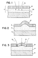
- FIG. 1 shows one embodiment of the optical data storage medium of the present invention and a focused laser recording beam.
- FIG. 2 shows the elastic and viscoelastic shear deformation of the medium of FIG. 1 during the recording phase.
- FIG. 3 shows the viscoelastic shear deformation of the medium of FIG. 1 and the focused laser erasing beam.
- Referring to FIG. 1, an exemplary embodiment of the optical
data storage medium 10 of the present invention is shown supported on and bonded to asubstrate 12, typically of glass, plastic, or aluminum. The recording medium includes two layers, anunderlying expansion layer 14 proximate thesubstrate 12 and anoverlying retention layer 16 integrally bonded to the expansion layer. - In the exemplary embodiment, the expansion layer is generally a cross-linked elastomer having (1) low thermal conductivity, (2) a high coefficient of thermal expansion, and (3) a glass transition temperature, Tg, considerably below the glass transition temperature of the retention layer. Accordingly, the expansion layer may be rubbery at ambient temperature as opposed, for example, to being in a glassy or brittle condition. This means that only relatively low-power heating is required to heat the rubbery material, resulting in localized, extensive, and rapid expansion of a portion of the expansion layer due to the three aforementioned properties. As a result of such localized expansion, high data storage density can be achieved. The material of the expansion layer may also be relatively highly cross-linked, so that upon expansion there is substantially no viscous flow of the material. In addition, the material of the expansion layer is elastic, having a high yield strain, so that when it is held in an extended state it will not exceed its elastic limit. Other properties and characteristics of the expansion layer will be described below.
- The retention layer is generally a polymeric material having a glass transition temperature, Tg, considerably above that of the expansion layer. Thus, at ambient or normal temperatures the retention layer is glassy or brittle, but when heated above its glass transition temperature, Tg, transforms through a leathery or pliable condition into a rubbery condition. The material of the retention layer also has a relatively low thermal conductivity. Therefore, low-power heat can be used to quickly and locally, but only slightly, expand material of the retention layer.
- The material of the retention layer is preferably not highly cross-linked but depends upon polymer chain entanglements to prevent excessive flow. As a result, thermoplastic materials may be suitable for the retention layer while some thermoset materials will not be suitable. Upon expansion, the chain entanglements limit viscous flow and some stretching of the material occurs. Furthermore, the retention layer preferably has a modulus of elasticity that varies with temperature. The modulus decreases with increasing temperature. Finally, the material of the retention layer is capable of undergoing substantial viscoelastic shear when below its Tg.
- At ambient temperature the expansion layer tends to be soft and rubbery and the retention layer tends to be hard and glassy. Both layers are semitransparent, the expansion layer dyed to selectively absorb light in a narrow wavelength band centered around a first wavelength L₁, and the retention layer dyed to selectively absorb light in a narrow wavelength band of light centered around a second wavelength L₂.
- Referring to FIG. 1 it will be noted that the expansion layer has a thickness greater than the retention layer. The expansion layer has a skin depth which is substantially less than its thickness. (The skin depth is the depth at which approximately 63 percent of the energy of the light entering the layer will be absorbed.) The skin depth of the retention layer is preferably less than or equal to its thickness.
- According to the method of the present invention, in order to record data on the medium 10, a focused laser beam B₁ shown in FIG. 1 having a wavelength of L₁ is directed at the medium. Since the retention layer is dyed to absorb light at wavelength L₂, the first laser beam B₁ having a wavelength of L₁ passes through the retention layer and into the expansion layer where most of the energy of the beam is absorbed by that portion of the expansion layer corresponding to the
skin depth 20. As a result, a small area of the expansion layer which is within the skin depth and struck by the beam is heated by the energy of the beam and expands rapidly. - As shown in FIG. 2, the rapid localized swelling of a portion of the expansion layer pushes the overlying retention layer up, causing first elastic shear deformation, and then viscoelastic shear deformation resulting in a
bump 22 on the surface of the medium. The thickness of the expansion layer along with the properties of the material discussed above cooperate to direct the expansion of the material of the expansion layer toward the overlying retention layer. It is important to understand that during the recording step, although the retention layer may be heated somewhat as a result of its proximity to the heated expansion layer, such incidental heating does not raise it above its glass transition temperature. - In this respect the method of the present invention differs substantially from the prior art method such as applicant's prior patent application or Cornet '656 which both rely upon heating of the retention layer to assist the deformation of that layer. Indeed, Cornet '656 actually heats the underlying expansion layer by first heating the overlying metal retention layer and relying upon the conductivity of the metal layer to heat the underlying expansion layer. It follows that the deformation occurring in the retention layer of the aforementioned prior art is elastic tensile deformation.
- The rapidly expanding material of the expansion layer causes the overlying portion of the retention layer to deform approximately along lines of shear, substantially perpendicular to the interface between the layers and to the plane of the medium. Imagine an array of pencils all standing on end. Pushing up on a group of these pencils from below would cause some of the pencils to move vertically with respect to each other, causing the top of the pencil array to form a bump.
- When the laser beam B₁ is shut off, the expansion layer cools and contracts, pulling down on the bump it has created in the overlying retention layer. The contracting expansion layer removes the elastic shear deformation from the retention layer, but cannot remove the viscoelastic shear deformation, resulting in an optically detectable bump on the surface of the medium as shown in FIG. 3. In the cooled configuration, the arched retention layer is in compression while the domed expansion layer is held up in tension because it is bonded to the retention layer.
- The viscoelastic shear deformation of the retention layer is caused by exceeding the shear elastic limit of the retention material. The retention layer can recover by a viscous flow of the material over a substantial period of time estimated by applicant to be between 10 and 100 years at ambient temperatures. However, the retention layer can recover quite quickly if it is raised above its glass transition temperature. FIG. 3 shows a laser beam B₂ having a wavelength of L₂ focused on the
bump 22 in the medium. Since the retention layer is dyed to absorb light energy having a wavelength of L₂, and since the skin depth of the retention layer is less than or at least not greater than its thickness, and because the expansion layer will not absorb substantial light having a wavelength L₂, laser beam B₂ heats substantially only the retention layer. When the temperature of the retention layer proximate the bump rises above its glass transition temperature, it becomes pliable. The underlying expansion layer, in tension, pulls the now pliable retention layer flat, relaxing the bump and erasing the deformation representing a data bit. - As to the generic materials and properties for practicing the present invention, applicant has found that a polyurethane expansion layer 2.0-6.0 micrometers ("µm") thick, dyed to achieve a skin depth of 0.8-1.2 µm for light having a wavelength of L₁, and having a tensile modulus at room temperature greater than 40,000 psi in combination with a retention layer of polyester copolymer or polycarbonate approximately 1.0-2.0 µm thick dyed to achieve a skin depth of .5 to 2.0 µm for light having a wavelength of L₂ and having a tensile modulus greater than 100,000 psi at room temperature are suitable.
- Two specific examples are provided.
- An expansion layer of urethane (Morton Thiokol-Solithane 113) 6.1 µm thick, dyed blue (Sandoz-Savinyl Blue RLS) having a skin depth of 0.96 µm for L₁ (633 nanometers ("nm")) and a skin depth of approximately 9 um for L₂ (488 nm). A retention layer of polyester resin ("PETG," Eastman Kodak-Kodar copolyester) 2.2 µm thick, dyed red (Sandoz Nitrofast Red BN) and having a skin depth of approximately 10 µm for L₁ (633 nm) and .26 µm for L₂ (488 nm).
- Beam B₁ (633 nm) was created using an HeNe laser which produced approximately 7.5 milliwatts ("mW") at the surface of the medium. Beam B₂ (488 nm) was created using a small air-cooled Argon laser which produced 3.8 mW at the surface of the medium. The diameter of the beam B₁ (633 nm) at the surface of the medium was approximately 1.5 µm (FWHM-Full Width Half Maximum) and that of beam B₂ (488 nm) was approximately 3.5 µm (FWHM).
- Using the medium and equipment described above, applicant was able to create an acceptable optically detectable deformation in the surface of the medium in 0.1s microseconds ("µs") of exposure to beam B₁ and was able to achieve acceptable erasure of the deformation in 2.2 µs of exposure to beam B₂.
- The expansion layer is the same as described above with respect to Example 1. The retention layer is of polycarbonate (Aldrich Chemical Co. 20,000-25,000 MW) 1.1 µm thick, dyed red (Sandoz Nitrofast Red BN) having a skin depth of approximately 13.0 µm for B₁ (633 nm) and a skin depth of 0.3 µm for B₂ (488 nm).
- Using the equipment described above, applicant was able to create an acceptable optically detectable deformation in 0.16µs of exposure to B₁ and achieve acceptable erasure in 2.5 µs exposure to beam B₂.
- As described in the examples set forth above, the power density requirements to write and erase are relatively low. Several factors contribute to this. First, since the process does not involve a change of state such as the ablative or vesicular techniques, less power is required. Similarly, the process does not entail a change of structure between crystal and amorphous as do other techniques. Finally, the medium does not include any metallic or other reflective material which would tend to reduce the efficiency of the scribing laser. The selective use of dyes to tune the material of the medium to absorb selected wavelengths at selected skin depths contributes to the efficient use of available laser power.
- Although an exemplary embodiment of the invention has been described above in terms of two discrete layers, applicant also envisons application of this cold working process to a single integral layer in which two or more zones have been created. The zones would correspond generally to the expansion and retention layers described herein, but would have a diffuse rather than discrete interface. Such zones could be created by washing the single integral layer with a combination of dyes, solvents and curing agents to produce zones having different optical, thermal, and mechanical properties as described herein.
- The terms and expressions which have been employed in the foregoing specification are used therein as terms of description and not of limitation, and there is no intention in the use of such terms and expressions of excluding equivalents of the features shown and described or portions thereof, it being recognized that the scope of the invention is defined and limited only by the claims which follow.
Claims (8)
Priority Applications (1)
| Application Number | Priority Date | Filing Date | Title |
|---|---|---|---|
| AT8787308682T ATE104791T1 (en) | 1986-10-02 | 1987-09-30 | MEDIUM AND METHOD FOR ERASABLE DATA RECORDING BY VISCOELASTIC SHEAR DEFORMATION. |
Applications Claiming Priority (2)
| Application Number | Priority Date | Filing Date | Title |
|---|---|---|---|
| US06/914,461 US4780867A (en) | 1986-10-02 | 1986-10-02 | Method for erasably recording data by viscoelastic shear deformation |
| US914461 | 1986-10-02 |
Publications (3)
| Publication Number | Publication Date |
|---|---|
| EP0262960A2 true EP0262960A2 (en) | 1988-04-06 |
| EP0262960A3 EP0262960A3 (en) | 1990-07-25 |
| EP0262960B1 EP0262960B1 (en) | 1994-04-20 |
Family
ID=25434403
Family Applications (1)
| Application Number | Title | Priority Date | Filing Date |
|---|---|---|---|
| EP87308682A Expired - Lifetime EP0262960B1 (en) | 1986-10-02 | 1987-09-30 | Medium and method for erasably recording data by viscoelastic shear deformation |
Country Status (6)
| Country | Link |
|---|---|
| US (1) | US4780867A (en) |
| EP (1) | EP0262960B1 (en) |
| JP (1) | JPS63136337A (en) |
| KR (1) | KR880005579A (en) |
| AT (1) | ATE104791T1 (en) |
| DE (1) | DE3789653T2 (en) |
Cited By (2)
| Publication number | Priority date | Publication date | Assignee | Title |
|---|---|---|---|---|
| EP0338776A2 (en) * | 1988-04-19 | 1989-10-25 | Optical Data, Inc. | Bump-forming media including thin intermediate reflective layer and methods for writing, reading, and erasing same |
| US5229507A (en) * | 1989-11-22 | 1993-07-20 | Ciba-Geigy Corporation | Substituted naphthalocyanines and their use |
Families Citing this family (26)
| Publication number | Priority date | Publication date | Assignee | Title |
|---|---|---|---|---|
| NL8503411A (en) * | 1985-12-11 | 1987-07-01 | Philips Nv | DEVICE FOR DETERMINING A CENTERING ERROR OF A ROUND TRACKED INFORMATION STRUCTURE IN AN OPTICAL REGISTRATION CARRIER WITH REGARD TO THE ROTATING AXIS OF A TURNTABLE ON WHICH THE REGISTRATION CARRIER IS INCLUDED IN A PURPOSE, INCLUDING ANY APPARATUS, INCLUDING ANY APPARATUS. |
| US4901304A (en) * | 1986-10-08 | 1990-02-13 | Optical Data, Inc. | Erasable optical data storage medium having a zoned integral recording layer |
| US5214632A (en) * | 1987-12-23 | 1993-05-25 | U.S. Philips Corporation | Method of manufacturing a matrix and a master plate suitable for use in the method |
| US5001035A (en) * | 1988-01-06 | 1991-03-19 | U.S. Philips Corporation | Method of recording information, recording element manufactured according to the method and method of producing a metal matrix |
| US5090008A (en) * | 1988-02-05 | 1992-02-18 | Tandy Corporation | Erasable recording media |
| US5016239A (en) * | 1988-02-05 | 1991-05-14 | Tandy Corporation | Recording method and apparatus |
| US5088088A (en) * | 1988-02-05 | 1992-02-11 | Tandy Corporation | Dye-polymer optical data storage media with improved recording sensitivity |
| US5014259A (en) * | 1988-02-05 | 1991-05-07 | Tandy Corporation | Recording medium having an insulating layer |
| US5036511A (en) * | 1988-02-05 | 1991-07-30 | Tandy Corporation | Recording method and apparatus |
| US4970711A (en) * | 1988-02-05 | 1990-11-13 | Tandy Corporation | Bulk eraser for optical memory media |
| US5001699A (en) * | 1988-02-05 | 1991-03-19 | Tandy Corporation | Recording method and apparatus |
| US5208801A (en) * | 1988-02-05 | 1993-05-04 | Tandy Corporation | Method and apparatus for correcting focus in an optical recording system |
| US5018128A (en) * | 1988-02-05 | 1991-05-21 | Tandy Corporation | Apparatus and medium for recording erasable information |
| US4918682A (en) * | 1988-02-05 | 1990-04-17 | Tandy Corporation | Ablative and bump-forming optical recording media including a metallic reflective layer |
| US5200948A (en) * | 1988-02-05 | 1993-04-06 | Tandy Corporation | Recording method and apparatus |
| US5155723A (en) * | 1988-07-30 | 1992-10-13 | Yuden Co., Ltd. Taiyo | Optical information recording method and medium |
| US5113213A (en) * | 1989-01-13 | 1992-05-12 | Sandor Ellen R | Computer-generated autostereography method and apparatus |
| US5079758A (en) * | 1989-09-28 | 1992-01-07 | Tandy Corporation | Single polymer layer recordable/erasable optical media |
| US5144613A (en) * | 1990-07-26 | 1992-09-01 | Tandy Corporation | Thermal bulk erasure method for dye polymer optical media |
| US5406544A (en) * | 1991-07-25 | 1995-04-11 | Clark; Bryan K. | Low cost substrate for bump-forming recording media |
| US5330799A (en) * | 1992-09-15 | 1994-07-19 | The Phscologram Venture, Inc. | Press polymerization of lenticular images |
| US5519794A (en) * | 1994-04-01 | 1996-05-21 | Rotaventure L.L.C. | Computer-generated autostereography method and apparatus |
| AUPP699698A0 (en) * | 1998-11-06 | 1998-12-03 | Pacific Solar Pty Limited | Indirect laser patterning of resist |
| AU757477B2 (en) * | 1998-11-06 | 2003-02-20 | Pacific Solar Pty Limited | Indirect laser patterning of resist |
| EP1178479A3 (en) * | 2000-08-01 | 2002-05-15 | TDK Corporation | Optical information medium |
| US20050194424A1 (en) * | 2004-03-03 | 2005-09-08 | Sproat William H. | Apparatus and method for sonic welding and materials forming |
Citations (5)
| Publication number | Priority date | Publication date | Assignee | Title |
|---|---|---|---|---|
| GB2061595A (en) * | 1979-10-17 | 1981-05-13 | Rca Corp | Optical recording medium |
| EP0046104A1 (en) * | 1980-08-13 | 1982-02-17 | Thomson-Csf | Thermo-optical process for information recording, record carrier for carrying out this process and apparatus to read this record carrier |
| EP0089168A1 (en) * | 1982-03-15 | 1983-09-21 | Kabushiki Kaisha Toshiba | Optical type information recording medium |
| US4408213A (en) * | 1981-10-30 | 1983-10-04 | Rca Corporation | Reinforced bubble recording medium and information record |
| EP0136070A1 (en) * | 1983-08-22 | 1985-04-03 | Optical Data, Inc. | Erasable optical data storage medium and method for recording data on the medium |
Family Cites Families (10)
| Publication number | Priority date | Publication date | Assignee | Title |
|---|---|---|---|---|
| US4264986A (en) * | 1979-03-12 | 1981-04-28 | Willis Craig I | Information-recording process & apparatus |
| US4285056A (en) * | 1979-10-17 | 1981-08-18 | Rca Corporation | Replicable optical recording medium |
| FR2474223A1 (en) * | 1980-01-23 | 1981-07-24 | Thomson Csf | METHOD FOR THERMO-OPTICAL INFORMATION REGISTRATION AND INFORMATION CARRIER FOR IMPLEMENTING SAID METHOD |
| FR2474222A1 (en) * | 1980-01-23 | 1981-07-24 | Thomson Csf | METHOD FOR THERMO-OPTICAL INFORMATION REGISTRATION AND INFORMATION CARRIER FOR IMPLEMENTING SAID METHOD |
| FR2475270A1 (en) * | 1980-02-01 | 1981-08-07 | Thomson Csf | REVERSIBLE MEMORY STRUCTURE, THERMO-OPTICAL INTEGRATION AND OPTICAL READING, AND METHOD FOR INSCRIPTION AND ERASURE OF THIS STRUCTURE |
| FR2475271A1 (en) * | 1980-02-01 | 1981-08-07 | Thomson Csf | PERMANENT MEMORY STRUCTURE, THERMO-OPTICAL REGISTRATION AND OPTICAL READING, AND METHOD OF REGISTRATION IN SUCH A STRUCTURE |
| US4336545A (en) * | 1980-12-18 | 1982-06-22 | Eastman Kodak Company | Optical disc structure, method and apparatus physically optimized for writing and reading with a single wavelength |
| US4430659A (en) * | 1981-02-13 | 1984-02-07 | Minnesota Mining And Manufacturing Company | Protuberant optical recording medium |
| US4599718A (en) * | 1981-04-07 | 1986-07-08 | Tdk Electronics Co., Ltd. | Method for erasing a light recording medium |
| US4719615A (en) * | 1983-08-22 | 1988-01-12 | Optical Data, Inc. | Erasable optical data storage medium |
-
1986
- 1986-10-02 US US06/914,461 patent/US4780867A/en not_active Expired - Fee Related
-
1987
- 1987-09-30 EP EP87308682A patent/EP0262960B1/en not_active Expired - Lifetime
- 1987-09-30 DE DE3789653T patent/DE3789653T2/en not_active Expired - Fee Related
- 1987-09-30 AT AT8787308682T patent/ATE104791T1/en active
- 1987-10-02 JP JP62248172A patent/JPS63136337A/en active Pending
- 1987-10-02 KR KR870011059A patent/KR880005579A/en not_active Application Discontinuation
Patent Citations (5)
| Publication number | Priority date | Publication date | Assignee | Title |
|---|---|---|---|---|
| GB2061595A (en) * | 1979-10-17 | 1981-05-13 | Rca Corp | Optical recording medium |
| EP0046104A1 (en) * | 1980-08-13 | 1982-02-17 | Thomson-Csf | Thermo-optical process for information recording, record carrier for carrying out this process and apparatus to read this record carrier |
| US4408213A (en) * | 1981-10-30 | 1983-10-04 | Rca Corporation | Reinforced bubble recording medium and information record |
| EP0089168A1 (en) * | 1982-03-15 | 1983-09-21 | Kabushiki Kaisha Toshiba | Optical type information recording medium |
| EP0136070A1 (en) * | 1983-08-22 | 1985-04-03 | Optical Data, Inc. | Erasable optical data storage medium and method for recording data on the medium |
Cited By (3)
| Publication number | Priority date | Publication date | Assignee | Title |
|---|---|---|---|---|
| EP0338776A2 (en) * | 1988-04-19 | 1989-10-25 | Optical Data, Inc. | Bump-forming media including thin intermediate reflective layer and methods for writing, reading, and erasing same |
| EP0338776A3 (en) * | 1988-04-19 | 1990-07-25 | Optical Data, Inc. | Bump-forming media including thin intermediate reflective layer and methods for writing, reading, and erasing same |
| US5229507A (en) * | 1989-11-22 | 1993-07-20 | Ciba-Geigy Corporation | Substituted naphthalocyanines and their use |
Also Published As
| Publication number | Publication date |
|---|---|
| EP0262960B1 (en) | 1994-04-20 |
| US4780867A (en) | 1988-10-25 |
| EP0262960A3 (en) | 1990-07-25 |
| ATE104791T1 (en) | 1994-05-15 |
| KR880005579A (en) | 1988-06-29 |
| JPS63136337A (en) | 1988-06-08 |
| DE3789653D1 (en) | 1994-05-26 |
| DE3789653T2 (en) | 1994-10-20 |
Similar Documents
| Publication | Publication Date | Title |
|---|---|---|
| EP0262960B1 (en) | Medium and method for erasably recording data by viscoelastic shear deformation | |
| EP0338776B1 (en) | Bump-forming media including thin intermediate reflective layer and methods for writing, reading, and erasing same | |
| US4719615A (en) | Erasable optical data storage medium | |
| JPH02504565A (en) | Optical data storage medium with stereomorphic energy absorption properties | |
| US4918682A (en) | Ablative and bump-forming optical recording media including a metallic reflective layer | |
| EP0263641A2 (en) | Method for making an erasable optical data storage medium | |
| US4879709A (en) | Dye-polymer optical data storage media with improved recording sensitivity | |
| EP0333462A3 (en) | Magneto-optical recording system having medium with domainless control layer | |
| KR900701004A (en) | Recording method and apparatus | |
| US4774702A (en) | Erasable optical memory employing a marmen alloy to effect phase-change erasing in a chalcogenide film | |
| US5144613A (en) | Thermal bulk erasure method for dye polymer optical media | |
| US5088088A (en) | Dye-polymer optical data storage media with improved recording sensitivity | |
| JP2705330B2 (en) | Optical recording medium | |
| JPH03141028A (en) | Recording and erasing method for optical disk | |
| JP2510320B2 (en) | Optical recording medium | |
| JPS62107448A (en) | Optical recording system | |
| JP2763243B2 (en) | Organic optical recording tape, recording and reproducing method thereof, and erasing device | |
| JP2507057B2 (en) | Optical information recording medium | |
| JPH02189738A (en) | Optical recording medium | |
| JPH01159839A (en) | Optical recording medium | |
| KR100209629B1 (en) | Recording method and disc drive in phase changing type optical disc | |
| JP2906551B2 (en) | Optical recording method | |
| JP2906550B2 (en) | Optical recording medium | |
| JPH0267181A (en) | Rewritable optical recording medium and erasure method thereof | |
| JPH04173184A (en) | Optical recording medium and recording, regenerating and erasing method using the same |
Legal Events
| Date | Code | Title | Description |
|---|---|---|---|
| PUAI | Public reference made under article 153(3) epc to a published international application that has entered the european phase |
Free format text: ORIGINAL CODE: 0009012 |
|
| AK | Designated contracting states |
Kind code of ref document: A2 Designated state(s): AT BE CH DE ES FR GB GR IT LI LU NL SE |
|
| PUAL | Search report despatched |
Free format text: ORIGINAL CODE: 0009013 |
|
| AK | Designated contracting states |
Kind code of ref document: A3 Designated state(s): AT BE CH DE ES FR GB GR IT LI LU NL SE |
|
| 17P | Request for examination filed |
Effective date: 19901227 |
|
| 17Q | First examination report despatched |
Effective date: 19911030 |
|
| GRAA | (expected) grant |
Free format text: ORIGINAL CODE: 0009210 |
|
| RAP1 | Party data changed (applicant data changed or rights of an application transferred) |
Owner name: PHILIPS ELECTRONICS N.V. |
|
| AK | Designated contracting states |
Kind code of ref document: B1 Designated state(s): AT BE CH DE ES FR GB GR IT LI LU NL SE |
|
| PG25 | Lapsed in a contracting state [announced via postgrant information from national office to epo] |
Ref country code: SE Free format text: THE PATENT HAS BEEN ANNULLED BY A DECISION OF A NATIONAL AUTHORITY Effective date: 19940420 Ref country code: LI Effective date: 19940420 Ref country code: GR Free format text: LAPSE BECAUSE OF FAILURE TO SUBMIT A TRANSLATION OF THE DESCRIPTION OR TO PAY THE FEE WITHIN THE PRESCRIBED TIME-LIMIT Effective date: 19940420 Ref country code: CH Effective date: 19940420 Ref country code: BE Effective date: 19940420 Ref country code: AT Effective date: 19940420 |
|
| REF | Corresponds to: |
Ref document number: 104791 Country of ref document: AT Date of ref document: 19940515 Kind code of ref document: T |
|
| REF | Corresponds to: |
Ref document number: 3789653 Country of ref document: DE Date of ref document: 19940526 |
|
| REG | Reference to a national code |
Ref country code: GB Ref legal event code: 732E |
|
| ITF | It: translation for a ep patent filed |
Owner name: ING. C. GREGORJ S.P.A. |
|
| REG | Reference to a national code |
Ref country code: CH Ref legal event code: PL |
|
| PG25 | Lapsed in a contracting state [announced via postgrant information from national office to epo] |
Ref country code: ES Free format text: LAPSE BECAUSE OF FAILURE TO SUBMIT A TRANSLATION OF THE DESCRIPTION OR TO PAY THE FEE WITHIN THE PRESCRIBED TIME-LIMIT Effective date: 19940731 |
|
| ET | Fr: translation filed | ||
| PGFP | Annual fee paid to national office [announced via postgrant information from national office to epo] |
Ref country code: GB Payment date: 19940901 Year of fee payment: 8 |
|
| REG | Reference to a national code |
Ref country code: FR Ref legal event code: TP |
|
| PGFP | Annual fee paid to national office [announced via postgrant information from national office to epo] |
Ref country code: FR Payment date: 19940928 Year of fee payment: 8 |
|
| PG25 | Lapsed in a contracting state [announced via postgrant information from national office to epo] |
Ref country code: LU Free format text: LAPSE BECAUSE OF NON-PAYMENT OF DUE FEES Effective date: 19940930 |
|
| PGFP | Annual fee paid to national office [announced via postgrant information from national office to epo] |
Ref country code: NL Payment date: 19940930 Year of fee payment: 8 |
|
| NLS | Nl: assignments of ep-patents |
Owner name: N.V. PHILIPS' GLOEILAMPENFABRIEKEN TE EINDHOVEN. |
|
| PGFP | Annual fee paid to national office [announced via postgrant information from national office to epo] |
Ref country code: DE Payment date: 19941125 Year of fee payment: 8 |
|
| PLBE | No opposition filed within time limit |
Free format text: ORIGINAL CODE: 0009261 |
|
| STAA | Information on the status of an ep patent application or granted ep patent |
Free format text: STATUS: NO OPPOSITION FILED WITHIN TIME LIMIT |
|
| 26N | No opposition filed | ||
| ITPR | It: changes in ownership of a european patent |
Owner name: CAMBIO RAGIONE SOCIALE;PHILIPS ELECTRONICS N.V. |
|
| PG25 | Lapsed in a contracting state [announced via postgrant information from national office to epo] |
Ref country code: GB Effective date: 19950930 |
|
| PG25 | Lapsed in a contracting state [announced via postgrant information from national office to epo] |
Ref country code: NL Effective date: 19960401 |
|
| GBPC | Gb: european patent ceased through non-payment of renewal fee |
Effective date: 19950930 |
|
| PG25 | Lapsed in a contracting state [announced via postgrant information from national office to epo] |
Ref country code: FR Effective date: 19960531 |
|
| PG25 | Lapsed in a contracting state [announced via postgrant information from national office to epo] |
Ref country code: DE Effective date: 19960601 |
|
| NLV4 | Nl: lapsed or anulled due to non-payment of the annual fee |
Effective date: 19960401 |
|
| REG | Reference to a national code |
Ref country code: FR Ref legal event code: ST |
|
| PG25 | Lapsed in a contracting state [announced via postgrant information from national office to epo] |
Ref country code: IT Free format text: LAPSE BECAUSE OF NON-PAYMENT OF DUE FEES;WARNING: LAPSES OF ITALIAN PATENTS WITH EFFECTIVE DATE BEFORE 2007 MAY HAVE OCCURRED AT ANY TIME BEFORE 2007. THE CORRECT EFFECTIVE DATE MAY BE DIFFERENT FROM THE ONE RECORDED. Effective date: 20050930 |