EP0262833B1 - Thermal fixing roller for use in a copying machine and method for manufacturing the same - Google Patents
Thermal fixing roller for use in a copying machine and method for manufacturing the same Download PDFInfo
- Publication number
- EP0262833B1 EP0262833B1 EP87308128A EP87308128A EP0262833B1 EP 0262833 B1 EP0262833 B1 EP 0262833B1 EP 87308128 A EP87308128 A EP 87308128A EP 87308128 A EP87308128 A EP 87308128A EP 0262833 B1 EP0262833 B1 EP 0262833B1
- Authority
- EP
- European Patent Office
- Prior art keywords
- roller
- resistor
- heat
- film
- layer
- Prior art date
- Legal status (The legal status is an assumption and is not a legal conclusion. Google has not performed a legal analysis and makes no representation as to the accuracy of the status listed.)
- Expired - Lifetime
Links
- 238000004519 manufacturing process Methods 0.000 title claims description 4
- 238000000034 method Methods 0.000 title description 11
- 239000010408 film Substances 0.000 claims description 39
- 239000012212 insulator Substances 0.000 claims description 28
- 239000000463 material Substances 0.000 claims description 26
- 238000005507 spraying Methods 0.000 claims description 16
- 229910052782 aluminium Inorganic materials 0.000 claims description 12
- XAGFODPZIPBFFR-UHFFFAOYSA-N aluminium Chemical compound [Al] XAGFODPZIPBFFR-UHFFFAOYSA-N 0.000 claims description 12
- 239000004411 aluminium Substances 0.000 claims description 11
- 239000011248 coating agent Substances 0.000 claims description 9
- 238000000576 coating method Methods 0.000 claims description 9
- 230000000873 masking effect Effects 0.000 claims description 8
- 229920005989 resin Polymers 0.000 claims description 8
- 239000011347 resin Substances 0.000 claims description 8
- YCKRFDGAMUMZLT-UHFFFAOYSA-N Fluorine atom Chemical compound [F] YCKRFDGAMUMZLT-UHFFFAOYSA-N 0.000 claims description 7
- 229910052731 fluorine Inorganic materials 0.000 claims description 7
- 239000011737 fluorine Substances 0.000 claims description 7
- 229910000679 solder Inorganic materials 0.000 claims description 6
- 229920006362 Teflon® Polymers 0.000 claims description 5
- 239000010409 thin film Substances 0.000 claims description 5
- PNEYBMLMFCGWSK-UHFFFAOYSA-N aluminium oxide Inorganic materials [O-2].[O-2].[O-2].[Al+3].[Al+3] PNEYBMLMFCGWSK-UHFFFAOYSA-N 0.000 claims description 4
- 229920002050 silicone resin Polymers 0.000 claims description 4
- RYGMFSIKBFXOCR-UHFFFAOYSA-N Copper Chemical compound [Cu] RYGMFSIKBFXOCR-UHFFFAOYSA-N 0.000 claims description 3
- 229910001374 Invar Inorganic materials 0.000 claims description 3
- 229910052596 spinel Inorganic materials 0.000 claims description 3
- 239000011029 spinel Substances 0.000 claims description 3
- 238000004804 winding Methods 0.000 claims description 3
- 239000011295 pitch Substances 0.000 description 20
- 229910052751 metal Inorganic materials 0.000 description 14
- 239000002184 metal Substances 0.000 description 14
- 238000009826 distribution Methods 0.000 description 9
- CPLXHLVBOLITMK-UHFFFAOYSA-N Magnesium oxide Chemical compound [Mg]=O CPLXHLVBOLITMK-UHFFFAOYSA-N 0.000 description 4
- 238000010438 heat treatment Methods 0.000 description 4
- 230000007423 decrease Effects 0.000 description 3
- 230000003247 decreasing effect Effects 0.000 description 3
- 239000007921 spray Substances 0.000 description 3
- PXHVJJICTQNCMI-UHFFFAOYSA-N Nickel Chemical compound [Ni] PXHVJJICTQNCMI-UHFFFAOYSA-N 0.000 description 2
- 230000015572 biosynthetic process Effects 0.000 description 2
- 238000003754 machining Methods 0.000 description 2
- 239000000395 magnesium oxide Substances 0.000 description 2
- 229910001120 nichrome Inorganic materials 0.000 description 2
- 238000007790 scraping Methods 0.000 description 2
- 229910001220 stainless steel Inorganic materials 0.000 description 2
- 239000010935 stainless steel Substances 0.000 description 2
- 239000000919 ceramic Substances 0.000 description 1
- 239000003795 chemical substances by application Substances 0.000 description 1
- 238000005520 cutting process Methods 0.000 description 1
- 238000010586 diagram Methods 0.000 description 1
- 238000002474 experimental method Methods 0.000 description 1
- 230000017525 heat dissipation Effects 0.000 description 1
- 238000007733 ion plating Methods 0.000 description 1
- 230000004048 modification Effects 0.000 description 1
- 238000012986 modification Methods 0.000 description 1
- 229910052759 nickel Inorganic materials 0.000 description 1
- 238000010433 powder painting Methods 0.000 description 1
- 230000005855 radiation Effects 0.000 description 1
- 238000004904 shortening Methods 0.000 description 1
- 238000004544 sputter deposition Methods 0.000 description 1
- 238000007740 vapor deposition Methods 0.000 description 1
Images


Classifications
-
- G—PHYSICS
- G03—PHOTOGRAPHY; CINEMATOGRAPHY; ANALOGOUS TECHNIQUES USING WAVES OTHER THAN OPTICAL WAVES; ELECTROGRAPHY; HOLOGRAPHY
- G03G—ELECTROGRAPHY; ELECTROPHOTOGRAPHY; MAGNETOGRAPHY
- G03G15/00—Apparatus for electrographic processes using a charge pattern
- G03G15/20—Apparatus for electrographic processes using a charge pattern for fixing, e.g. by using heat
- G03G15/2003—Apparatus for electrographic processes using a charge pattern for fixing, e.g. by using heat using heat
- G03G15/2014—Apparatus for electrographic processes using a charge pattern for fixing, e.g. by using heat using heat using contact heat
- G03G15/2053—Structural details of heat elements, e.g. structure of roller or belt, eddy current, induction heating
-
- H—ELECTRICITY
- H05—ELECTRIC TECHNIQUES NOT OTHERWISE PROVIDED FOR
- H05B—ELECTRIC HEATING; ELECTRIC LIGHT SOURCES NOT OTHERWISE PROVIDED FOR; CIRCUIT ARRANGEMENTS FOR ELECTRIC LIGHT SOURCES, IN GENERAL
- H05B3/00—Ohmic-resistance heating
- H05B3/0095—Heating devices in the form of rollers
-
- Y—GENERAL TAGGING OF NEW TECHNOLOGICAL DEVELOPMENTS; GENERAL TAGGING OF CROSS-SECTIONAL TECHNOLOGIES SPANNING OVER SEVERAL SECTIONS OF THE IPC; TECHNICAL SUBJECTS COVERED BY FORMER USPC CROSS-REFERENCE ART COLLECTIONS [XRACs] AND DIGESTS
- Y10—TECHNICAL SUBJECTS COVERED BY FORMER USPC
- Y10T—TECHNICAL SUBJECTS COVERED BY FORMER US CLASSIFICATION
- Y10T29/00—Metal working
- Y10T29/49—Method of mechanical manufacture
- Y10T29/49002—Electrical device making
- Y10T29/49082—Resistor making
- Y10T29/49083—Heater type
-
- Y—GENERAL TAGGING OF NEW TECHNOLOGICAL DEVELOPMENTS; GENERAL TAGGING OF CROSS-SECTIONAL TECHNOLOGIES SPANNING OVER SEVERAL SECTIONS OF THE IPC; TECHNICAL SUBJECTS COVERED BY FORMER USPC CROSS-REFERENCE ART COLLECTIONS [XRACs] AND DIGESTS
- Y10—TECHNICAL SUBJECTS COVERED BY FORMER USPC
- Y10T—TECHNICAL SUBJECTS COVERED BY FORMER US CLASSIFICATION
- Y10T428/00—Stock material or miscellaneous articles
- Y10T428/13—Hollow or container type article [e.g., tube, vase, etc.]
- Y10T428/1352—Polymer or resin containing [i.e., natural or synthetic]
- Y10T428/1355—Elemental metal containing [e.g., substrate, foil, film, coating, etc.]
Definitions
- the present invention relates to a thermal fixing roller for use in an electronic copying machine, and more particularly, to a thermal fixing roller for thermally fixing a dry type developing agent consisting principally of colored toner and resin on a support in an electronic copying machine.
- a heater is provided on the inside of a metallic support of cylindrical shape, and the surface of the thermal fixing roller is heated by this heater.
- the heat-up time that is, the time period necessitated from start of the copying machine until the copying machine becomes available is long, and it takes about 1 to 2 minutes.
- a thermal fixing roller of the so-called planar heat-generating resistor type, in which a planar heat-generating resistor is provided on a surface of a support for the purpose of shortening the above-mentioned heat-up time, an electric current is passed from one end of the resistor towards the other end, and the roller surface is directly heated by Joule's heat generated at this time.
- this planar heater is uniform over its entire length and the opposite end portions of the heater are liable to be cooled as compared to its central portion, surface temperature distribution in the axial direction of the thermal fixing roller is such that the temperature at the opposite end portions of the roller is lower than that at the central portion. Consequently, it becomes difficult to attain a uniform picture.
- the thickness of the resistor film is thin, for example, 50 ⁇ m, it is extremely difficult to scrape this film up to a desired thickness, and therefore, temperature distribution on a roller surface is liable to become uneven.
- the object of the present invention is to provide a low cost thermal fixing roller with surface temperature distribution on the roller substantially uniform.
- a thermal fixing roller is characterised in that the resistor has a portion in a region of the roller needing a higher heat generating rate formed narrower in width than a portion in a remaining region needing a lower heat generating rate.
- a current is passed through the belt-like heat-generating resistor to heat the resistor by Joule's heat of the current.
- the resistance is made larger at the opposite end portions of the roller than its central portion by varying the pitch of the heat-generating resistor in the above-described manner, thereby a heat-generating rate at the opposite end portions is made larger than that at the central portion to make the heat-generating rate balance with the heat-dissipating rate from the opposite end portions, and the temperature distribution on the roller surface is made to be uniform over its entire length.
- the resistor is formed by providing a belt-like heat-generating resistor layer together with a groove or grooves formed in a helix manner on the surface of the insulative support, and an anti-adhesion layer is provided on the surfaces of these, in which a cross-section configuration of the groove taken along a plane containing the axis of the support is formed in a rectangular shape.
- the invention further provides a method for manufacturing the roller having the characteristics above defined consisting of the steps of winding a masking wire material having a rectangular cross-section in a helix manner around a surface of a cylindrical insulative support, forming a heat-generating resistor layer on the surface of the wound assembly, thereafter removing the wire material to form a groove at its trace, and then forming an anti-adhesion layer on the surface of the grooved assembly.
- reference character P0 designates a metallic hollow pipe. On the surface of this pipe P0 is formed an insulator layer 1 as shown in Fig. 2, and further, on the surface of the insulator layer 1 is formed a heat-generating resistor 2.
- This insulator layer is a thin film formed by plasma spray-coating alumina (Al2O3), spinel (Al2O3 ⁇ MgO) or the like, and its thickness is, for example, 200 ⁇ m.
- the heat-generating resistor 2 is formed in the following manner. At first, a masking wire material, for example, a metal wire 4 is wound in a spiral manner around the surface of the insulator layer 1 as shown in Fig. 3.
- a masking wire material for example, a metal wire 4 is wound in a spiral manner around the surface of the insulator layer 1 as shown in Fig. 3.
- this metal wire 4 it is preferable to use, for instance, an Invar wire of 0.6 mm in diameter for the purpose of preventing thermal expansion of the masking wire material upon thermal spray coating, but a copper wire could be used under a high tension.
- a pitch P of the metal wire 4 is successively narrowed in the order of a central portion 10c, a side portion 10b and an end portion 10a of the thermal fixing roller 10, and for instance, a pitch P1 of the end portion 10a is 4 mm, a pitch P2 of the side portion 10b is 5 mm and a pitch P3 of the central portion 10c is 6 mm.
- resistor material such as, for instance, nichrome, stainless steel, nickel, aluminium or aluminium solder is thermally spray-coated on the roller by means of a thermal spray-coating gun G, and thereby the heat-generating resistor 2 is formed.
- This resistor 2 is like a thin film, and its thickness d is, for instance, 40 ⁇ m.
- an anti-adhesion film 3 is formed on the surface of the roller, and this film 3 is formed up to a thickness t of, for example, 50 ⁇ m by fluorine resin or silicone resin coating.
- the surface of the anti-adhesion film 3 is smoothened by grinding, also an electric power feeding section 6 is provided at one end of the hollow pipe P0, another electric power feeding section 7 is provided at the other end, and these electric power feeding sections 6 and 7 are respectively connected to the opposite ends of the heat-generating resistor 2.
- the roller surface temperature rises due to Joule's heat, and since the pitch P of the heat-generating resistor 2 is successively narrowed in the order of the central portion 10c, the side portion 10b and the end portion 10a of the thermal fixing roller 10, in other words, the pitches P1 and P2 of the portions where a highest heat-generating rate and a higher heat generating rate are respectively necessitated, are smaller than the pitch P3 of the other portion, the roller surface temperature becomes uniform over its entire length.
- the pitch P of the resistor 2 is chosen such that the pitch P1 at an end portion 10a of the roller 10 is 4 mm, the pitch P2 at a side portion 10b is 5 mm and the pitch P3 at a central portion 10c is 6 mm, then because of the above-mentioned relation, the proportions of the resistances r becomes such that representing the proportion of the resistance at the end portion 10a is taken to be 1, that at the side portion 10b becomes 0.64 and that at the central portion 10c becomes 0.44.
- the current (power) feed to the heat-generating resistor 2 is effected continuously during a heat-up time, thereafter even if it is effected intermittently, the necessary roller surface temperature can be maintained.
- the resistance of the heat generating resistor 2 is chosen to be 10 ⁇ and a voltage of 100 V is applied thereto in the above-described embodiment, consumed electric power is 1 KW, the heat-up time up to 200°C is 10 seconds, and thus the heat-up time can be greatly shortened as compared to the heretofore known roller.
- a method for forming a belt-like heat-generating resistor in a helix manner it may be conceived to form a resistor film by coating resistor material over the entire surface of the insulator layer of the roller and then cutting a groove in this resistor film in a helix manner, but in this method, in order to perfectly separate adjacent resistor portions from each other, it is necessary to cut the groove somewhat deeply, that is, to an extent that the groove may dig in the insulator layer.
- the anti-adhesion film 3 is formed by coating fluorine resin on the resistor 2, the surface of the film 3 would naturally take a flat condition, and so, the above-mentioned problems relating to the grinding work would not occur.
- the present invention is not limited to the above-described preferred embodiment, but, for instance, the belt-like heat-generating resistor could be formed in a double helix shape.
- a metal wire 4 is wound in a double spiral shape around a surface of an insulator layer 1, aluminium solder or the like is spray coated thereon a form a heat-generating resistor 2, and thereafter when the metal wire 4 is removed, grooves 5 of a double helix shape would remain at the trace of the metal wire 4.
- pitches P3, P2 and P1 of the grooves 5 decrease successively from a central portion 10c of the roller towards its end portions 10a.
- This resistor 2 consists of a foward path resistor 2a and a backward path 2b as shown in Fig. 4, and one ends of these resistors 2a and 2b are electrically connected at a connecting portion 2c.
- an anti-adhesion film 3 is formed on the roller surface, and also in order to achieve simplification of wirings within a copying machine, electric power feeding sections 6 and 7 are provided at one end of a hollow pipe P0. Then the forward path resistor 2a is connected to the electric power feeding section 6, and the backward path resistor 2b is connected to the electric power feeding section 7.
- the current which has reached the connecting portion 2c is diverted at this point to flow through the backward path resistor 2b, and similarly to the above-mentioned process, it flows in the direction of arrow A7 while generating Joule's heat and a magnetic field and reaches the electric power feeding section 7.
- the magnetic field generated around the resistor 2a and the magnetic field generated around the resistor 2b would offset each other, and after all, the magnetic field around the resistors 2a and 2b, that is, around the heat-generating resistor 2 would almost disappear.
- the anti-adhesion film 3 becomes tough, also its surface becomes flat, and electrical safety is improved.
- the belt-like heat-generating resistor is formed in a spiral shape, if the pitch of the heat-generating resistor is gradually decreased from the central portion of the roller towards the opposite end portions, then the resistance at the opposite end portions becomes larger than the resistance at the central portion.
- a heat generating rate would be increased from the central portion of the roller towards the end portions, hence it can be balanced with heat dissipation from the opposite end portions, after all the surface temperature distribution in the axial direction of the roller becomes as represented by a straight line N in Fig. 8, and the entire roller surface is held at a uniform temperature.
- the belt-like heat-generating resistor is formed in a double helix shape, one ends of the helices are electrically connected to each other and the other ends of the spirals are respectively connected to separate electric power feeding sections, then when an electric current is fed from the electric power feeding section through the heat-generating resistor, the electric current reciprocates on the roller surface while flowing in a spiral manner.
- the magnetic fields generated in association with the forwards and backwards electric currents would offset each other and disappear, and so, a magnetic field is almost not present on the surface of the thermal fixing roller.
- reference numeral 10 designates an insulative support prepared by forming an insulator layer 1 on a surface of a metallic hollow pipe P0.
- This insulator layer 1 is a thin film formed by plasma spray coating alumina or magnesia alumina spinel (Mg Al2 O4), and its thickness is, for example, 200 ⁇ m.
- this insulator layer 1 On the surface of this insulator layer 1 is helically wound a masking wire material having a rectangular cross-section, for instance, a metal wire 4 having a cross-section of 0.1 mm in width by 0.3 mm in length, so as to come into surface contact with each other.
- a masking wire material having a rectangular cross-section, for instance, a metal wire 4 having a cross-section of 0.1 mm in width by 0.3 mm in length, so as to come into surface contact with each other.
- an Invar wire or a copper wire having a rectangular cross-section could be employed.
- heat-generating resistor material such as, for instance, nichrome, stainless steel, aluminium, aluminium solder, etc. is thermally spray-coated by making use of a thermal spray-coating gun on the insulator layer 1 having the metal wire 4 wound therearound and thereby the heat-generating resistor layer 2 is formed.
- heat-generating resistor material such as, for instance, nichrome, stainless steel, aluminium, aluminium solder, etc.
- a cross-section configuration of the groove 5 taken along a plane containing an axis C of the insulative support 10 is a rectangular shape of 30 ⁇ m in width by 0.3 mm in length, and the respective portions 2d and 2e of the heat-generating resistor 2 are perfectly separated by this groove 5.
- the heat-generating resistor portions 2d and 2e and the groove 5 are subjected to spray coating of fluorine resin or silicone resin by means of a powder painting gun P, and thereby an anti-adhesion layer 3 is formed.
- the thickness d 2 of the anti-adhesion layer 3 on resistor portions 2d,e is, for example, 100 ⁇ m, and the thickness d 3 of said layer above the groove 5 is, for example, 90 ⁇ m.
- the difference d 4 between the thickness d 2 and the thickness d3 is only 10 ⁇ m.
- the groove width W has been reduced considerably compared with that resulting from use of masking wire of circular cross section.
- the surface of the anti-adhesion layer 3 is ground to smooth the surface of the roller 10, and electric power feeding sections 6 and 7 are disposed at the end portions of the thermal fixing roller 10.
- the anti-adhesion layer as used according to the present invention could be composed of a lower layer consisting of a mechanically strong insulator layer, for instance a ceramic layer and an upper layer consisting of a Teflon® layer. If such provision is made, the mechanically weak Teflon® layer can be protected by the lower insulator layer, and also, the Teflon® layer can be formed thin. In addition, even if the Teflon® layer is made thin, the surface of the anti-adhesion layer can be easily flattened because the insulator layer lies thereunder.
- An insulator layer 1 is formed on a surface of a metallic hollow pipe P0 supported by a bearing 22, then a belt-like heat-generating resistor 2 and a groove 5 are formed alternately in a spiral shape on the surface of the insulator layer 1, and on the surface of this heat-generating resistor 2 is formed an anti-adhesion layer 3 by coating fluorine resin or silicone resin.
- a slip ring 11 is formed in a true round shape by machining, and in a central portion of its outer circumference is formed a recess 11a adapted to come into contact with a collector 12.
- the thickness T of the opposite end portions 11b and 11c of the slip ring 11 is made thicker than the thickness t of the anti-adhesion layer 3, and an end surface 11d of the end portion 11b continues to the surface of the anti-adhesion layer 3 via a smoothly curved surface.
- paper-sheets S would never enter between the slip ring 11 and the collector 12, and hence occurrence of fire can be prevented.
- the slip ring is preliminarily formed in a true round shape by machining, a slip ring having an excellent roundness can be obtained.
- the slip ring is fitted after formation of the anti-adhesion film, the slip ring is not subjected to heating upon formation of the anti-adhesion film, and hence it would not be oxidized. Accordingly, the resistance at this portion would not be increased, and therefore, stable power feeding can be achieved.
Landscapes
- Physics & Mathematics (AREA)
- General Physics & Mathematics (AREA)
- Fixing For Electrophotography (AREA)
- Control Of Resistance Heating (AREA)
Description
- The present invention relates to a thermal fixing roller for use in an electronic copying machine, and more particularly, to a thermal fixing roller for thermally fixing a dry type developing agent consisting principally of colored toner and resin on a support in an electronic copying machine.
- In a heretofore known thermal fixing roller, a heater is provided on the inside of a metallic support of cylindrical shape, and the surface of the thermal fixing roller is heated by this heater.
- However, since this heating process relies upon thermal radiation from the heater, the heat-up time, that is, the time period necessitated from start of the copying machine until the copying machine becomes available is long, and it takes about 1 to 2 minutes.
- Hence, a thermal fixing roller, of the so-called planar heat-generating resistor type, is employed, in which a planar heat-generating resistor is provided on a surface of a support for the purpose of shortening the above-mentioned heat-up time, an electric current is passed from one end of the resistor towards the other end, and the roller surface is directly heated by Joule's heat generated at this time.
- One example of this latter type of fixing roller is known from US-A-4109135 in which a belt-like heat generating resistor is formed in a helix shape on the surface of a cylindrical insulative support.
- However, as the thickness of this planar heater is uniform over its entire length and the opposite end portions of the heater are liable to be cooled as compared to its central portion, surface temperature distribution in the axial direction of the thermal fixing roller is such that the temperature at the opposite end portions of the roller is lower than that at the central portion. Consequently, it becomes difficult to attain a uniform picture.
- Therefore, in the prior art, a thermal fixing roller in which equalization of the above-mentioned temperature distribution was attempted by forming a film of a resistor on a thermal fixing roller in a fixed thickness, scraping this film of a resistor in the proximities of the opposite ends of the roller, and increasing resistances of these portions, was known (See Japanese Laid-Open Patent Specification No 59-154476(1984)). However, in this example of the prior art, a troublesome work of scraping a film of a resistor in the proximities of the opposite ends of the roller is necessitated and a lot of time and labor is necessary therefor, which causes rise of cost of a roller.
- In addition, since the thickness of the resistor film is thin, for example, 50 µm, it is extremely difficult to scrape this film up to a desired thickness, and therefore, temperature distribution on a roller surface is liable to become uneven.
- The object of the present invention is to provide a low cost thermal fixing roller with surface temperature distribution on the roller substantially uniform.
- According to the invention a thermal fixing roller is characterised in that the resistor has a portion in a region of the roller needing a higher heat generating rate formed narrower in width than a portion in a remaining region needing a lower heat generating rate.
- In use a current is passed through the belt-like heat-generating resistor to heat the resistor by Joule's heat of the current. The resistance is made larger at the opposite end portions of the roller than its central portion by varying the pitch of the heat-generating resistor in the above-described manner, thereby a heat-generating rate at the opposite end portions is made larger than that at the central portion to make the heat-generating rate balance with the heat-dissipating rate from the opposite end portions, and the temperature distribution on the roller surface is made to be uniform over its entire length.
- Preferably the resistor is formed by providing a belt-like heat-generating resistor layer together with a groove or grooves formed in a helix manner on the surface of the insulative support, and an anti-adhesion layer is provided on the surfaces of these, in which a cross-section configuration of the groove taken along a plane containing the axis of the support is formed in a rectangular shape.
- The invention further provides a method for manufacturing the roller having the characteristics above defined consisting of the steps of winding a masking wire material having a rectangular cross-section in a helix manner around a surface of a cylindrical insulative support, forming a heat-generating resistor layer on the surface of the wound assembly, thereafter removing the wire material to form a groove at its trace, and then forming an anti-adhesion layer on the surface of the grooved assembly.
-
- Fig. 1 is a plan view showing one preferred embodiment of the present invention;
- Fig. 2 is an enlarged partial cross-section view of the portion indicated by arrowed line II-II in Fig. 1;
- Fig. 3 is a schematic front view showing a process of forming a heat-generating resistor;
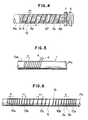
- Fig. 4 is a plan view showing another preferred embodiment of the present invention;
- Fig. 5 is a schematic plan view showing a method of windng a metal wire around a support for the embodiment shown in Fig. 4;
- Fig. 6 is a plan view showing the state where a metal wire has been removed after a heat-generating resistor was formed;
- Fig. 7 is an enlarged partial cross-section view corresponding to Fig. 2 in a further preferred embodiment of the present invention;
- Fig. 8 is a diagram showing temperature distribution on a roller surface;
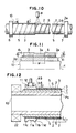
- Fig. 9 is a plan view showing a process of forming a heat-generating resistor in still another preferred embodiment of the present invention;
- Fig. 10 is a plan view showing a process of forming an anti-adhesion layer;
- Fig. 11 is an enlarged partial cross-section view of the portion indicated by arrowed line XI-XI in Fig. 10; and
- Fig. 12 is an enlarged longitudinal cross-section view of a part of yet another preferred embodiment of the present invention.
- In Fig. 1, reference character P₀ designates a metallic hollow pipe. On the surface of this pipe P₀ is formed an
insulator layer 1 as shown in Fig. 2, and further, on the surface of theinsulator layer 1 is formed a heat-generatingresistor 2. - This insulator layer is a thin film formed by plasma spray-coating alumina (Al₂O₃), spinel (Al₂O₃·MgO) or the like, and its thickness is, for example, 200 µm.
- The heat-generating
resistor 2 is formed in the following manner. At first, a masking wire material, for example, ametal wire 4 is wound in a spiral manner around the surface of theinsulator layer 1 as shown in Fig. 3. - As this
metal wire 4, it is preferable to use, for instance, an Invar wire of 0.6 mm in diameter for the purpose of preventing thermal expansion of the masking wire material upon thermal spray coating, but a copper wire could be used under a high tension. - A pitch P of the
metal wire 4 is successively narrowed in the order of acentral portion 10c, aside portion 10b and anend portion 10a of thethermal fixing roller 10, and for instance, a pitch P₁ of theend portion 10a is 4 mm, a pitch P₂ of theside portion 10b is 5 mm and a pitch P₃ of thecentral portion 10c is 6 mm. - After the
metal wire 4 has been wound in the above-described manner, resistor material such as, for instance, nichrome, stainless steel, nickel, aluminium or aluminium solder is thermally spray-coated on the roller by means of a thermal spray-coating gun G, and thereby the heat-generatingresistor 2 is formed. - The above-mentioned aluminum or aluminium solder is most suitable as resistor material because it does not change in resistance at a high temperature and moreover it is cheap. This
resistor 2 is like a thin film, and its thickness d is, for instance, 40 µm. - In this instance, by plasma spray coating or arc spray coating aluminium with air (Japanese Patent Application No. 60-181081 (1985) or 60-181082 (1985)), a stable heat-generating resistor can be formed. It is to be noted that instead of employing the above-described thermal spray coating, vapor deposition, sputtering, ion-plating, etc. could be employed. Thereafter, when the
metal wire 4 is removed from the surface of theroller 10, ahelical groove 5 is formed at its trace, hence the heat-generatingresistor 2 takes a helix form as shown in Fig. 1, and the pitch of this heat-generatingresistor 2, that is, the pitch P of themetal wire 4 decreases successively from thecentral portion 10c of the roller, via theside portion 10b towards theend portion 10a. - Subsequently, an
anti-adhesion film 3 is formed on the surface of the roller, and thisfilm 3 is formed up to a thickness t of, for example, 50 µm by fluorine resin or silicone resin coating. - After finishment of this coating, the surface of the
anti-adhesion film 3 is smoothened by grinding, also an electricpower feeding section 6 is provided at one end of the hollow pipe P₀, another electricpower feeding section 7 is provided at the other end, and these electricpower feeding sections resistor 2. - If an electric current is made to flow through the heat-generating
resistor 2 from the electricpower feeding section 6, this current flows in the direction of arrow A10 while heating theresistor 2 by Joule's heat and reaches the electricpower feeding section 7. - In this way, the roller surface temperature rises due to Joule's heat, and since the pitch P of the heat-generating
resistor 2 is successively narrowed in the order of thecentral portion 10c, theside portion 10b and theend portion 10a of thethermal fixing roller 10, in other words, the pitches P₁ and P₂ of the portions where a highest heat-generating rate and a higher heat generating rate are respectively necessitated, are smaller than the pitch P₃ of the other portion, the roller surface temperature becomes uniform over its entire length. - More particularly, if the resistance is denoted by R, the specific resistance of material by ρ, the length of the resistor by L, and the cross-section area of the resistor by S, then the resistance R is represented by the formula

- Now, indicating the pitch of the heat-generating resistor by P, its thickness by d, and the radius of the
insulator layer 1 by e, then the resistance r per unit distance in the direction of the roller axis of the resistor is represented by the formula
- Assuming that reference character C denotes a constant, the resistance r is represented by the formula r = C/P², that is, the resistance r per unit distance in the direction of the roller axis of the resistor is inversely proportional to the square of the pitch P of the heat-generating resistor.
- Accordingly, if the pitch P of the
resistor 2 is chosen such that the pitch P₁ at anend portion 10a of theroller 10 is 4 mm, the pitch P₂ at aside portion 10b is 5 mm and the pitch P₃ at acentral portion 10c is 6 mm, then because of the above-mentioned relation, the proportions of the resistances r becomes such that representing the proportion of the resistance at theend portion 10a is taken to be 1, that at theside portion 10b becomes 0.64 and that at thecentral portion 10c becomes 0.44. - Representing the current value by i, then the heat generating rate W per unit distance is indicated by the formula W = i²r according to the Joule's Law, that is, it is proportional to the resistance r, hence the heat generating rate W is increased successively from the
central portion 10c towards theend portion 10a, so that thermal dissipation from theopposite end portions 10a and from the bothside portions 10b can be balanced by the increased heat-generating rate, and after all, the surface temperature distribution in the direction of the roller axis would become uniform. - When the roller surface temperature distributions for the illustrated embodiment and for the heretofore known rollers were experimentally compared with each other, the results indicated in Fig. 8 were obtained. More particularly, in the case of the heretofore known roller, the results are reresented by curve "0", in which a temperature difference of about 30°C in average exists between the
roller end portion 10a and thecentral portion 10c, whereas in the case of the illustrated embodiment, the results are represented by curve "N", in which theentire roller surface 10a-10c is held uniformly at 200°C. - It is to be noted that although the current (power) feed to the heat-generating
resistor 2 is effected continuously during a heat-up time, thereafter even if it is effected intermittently, the necessary roller surface temperature can be maintained. In the case where the resistance of theheat generating resistor 2 is chosen to be 10Ω and a voltage of 100 V is applied thereto in the above-described embodiment, consumed electric power is 1 KW, the heat-up time up to 200°C is 10 seconds, and thus the heat-up time can be greatly shortened as compared to the heretofore known roller. - As a method for forming a belt-like heat-generating resistor in a helix manner, it may be conceived to form a resistor film by coating resistor material over the entire surface of the insulator layer of the roller and then cutting a groove in this resistor film in a helix manner, but in this method, in order to perfectly separate adjacent resistor portions from each other, it is necessary to cut the groove somewhat deeply, that is, to an extent that the groove may dig in the insulator layer.
- Consequently, when an anti-adhesion film is formed by coating fluorine resin on the resistor film, unevenness would arise on the surface and thus flatness is liable to be lost.
- Therefore, after an anti-adhesion film has been once formed thick, it is compelled to grind the surface of the anti-adhesion film to make it smooth, but this grinding work necessitates a lot of time, and moreover, would scrape away the expansive material for the anti-adhesion film, so that this causes rise of cost of the thermal fixing roller.
- Whereas, if the heat-generating resistor is formed through the above-mentioned process,
grooves 5 between adjacent portions of theresistor 2 become shallow because the thickness d of theresistor 2 can be made thin. - Accordingly, when the
anti-adhesion film 3 is formed by coating fluorine resin on theresistor 2, the surface of thefilm 3 would naturally take a flat condition, and so, the above-mentioned problems relating to the grinding work would not occur. - According experiments, if the width m of the
groove 5 is made to be 500 µm or less, for instance, to be 400 µm, ananti-adhesion film 3 having a film thickness t = 50 µm or less is formed by coating fluorine resin thereon and thefilm 3 is subjected to grinding to obtain surface smoothness that is necessary for preventing adhesion, then the surface would become a smooth surface to such extent that no inconvenience may arise in use. - The present invention is not limited to the above-described preferred embodiment, but, for instance, the belt-like heat-generating resistor could be formed in a double helix shape.
- This modified embodiment will be explained with reference to Figs. 4 to 6, in which items designated by the same reference numerals as those used in Figs. 1 to 3 have the same names and functions as the corresponding items in Figs. 1 to 3.
- As shown in Fig. 5, a
metal wire 4 is wound in a double spiral shape around a surface of aninsulator layer 1, aluminium solder or the like is spray coated thereon a form a heat-generatingresistor 2, and thereafter when themetal wire 4 is removed,grooves 5 of a double helix shape would remain at the trace of themetal wire 4. As shown in Fig. 6, pitches P₃, P₂ and P₁ of thegrooves 5 decrease successively from acentral portion 10c of the roller towards itsend portions 10a. Thisresistor 2 consists of afoward path resistor 2a and abackward path 2b as shown in Fig. 4, and one ends of theseresistors portion 2c. - Subsequently, an
anti-adhesion film 3 is formed on the roller surface, and also in order to achieve simplification of wirings within a copying machine, electricpower feeding sections forward path resistor 2a is connected to the electricpower feeding section 6, and thebackward path resistor 2b is connected to the electricpower feeding section 7. - If an electric current is made to flow from the electric
power feeding section 6 through theforward path resistor 2a, then this current flows in the direction of arrow A6 while heating theresistor 2a by Joule's heat and generating a magnetic field therearound, and reaches the connectingportion 2c. - Then, the current which has reached the connecting
portion 2c is diverted at this point to flow through thebackward path resistor 2b, and similarly to the above-mentioned process, it flows in the direction of arrow A7 while generating Joule's heat and a magnetic field and reaches the electricpower feeding section 7. - At this time, since the
forward path resistor 2a and thebackward path resistor 2b are formed in a double helix shape, the currents flowing through theseresistors - Consequently, the magnetic field generated around the
resistor 2a and the magnetic field generated around theresistor 2b would offset each other, and after all, the magnetic field around theresistors resistor 2 would almost disappear. By way of example, when the magnetic field strength at the location at a distance of 2 cm from the hollow pipe P₀, theinsulator layer 1 and the heat-generatingresistor 2, respectively, was measured, in the case of a belt-like heat-generating resistor of single helix shape, the highest measured value was 9.3 Gauss (10,000 Gauss = 1 Tesla) and the next high value was 7.2 Gauss, whereas in the case of a belt-like heat-generating resistor of double helix shape, the highest measured value was 0.4 Gauss and the next high value was 0.2 Gauss, and thus it was proved that if theresistor 2 is formed in a double helix shape, a magnetic field strength would be decreased remarkably. - In this modified embodiment also, since the pitches P of the heat-generating
resistors central portion 10c, theside portions 10b and theend portions 10a of the thermal fixingroller 10 as shown in Fig. 6, it is a matter of course that the surface temperature of the roller becomes uniform over its entire length similarly to the above-described first preferred embodiment. - While the belt-like heat-generating
resistor 2 is directly covered by an anti-adhesion film in the embodiment shown in Fig. 2, modification could be made thereto such that aninsulator film 1N is formed on the surface of the belt-like heat-generatingresistor 2 and ananti-adhesion film 3 is formed thereon as shown in Fig. 7. - If the
insulator film 1N is formed between the heat-generatingresistor 2 and the anti-adhesion film in the above-described manner, then theanti-adhesion film 3 becomes tough, also its surface becomes flat, and electrical safety is improved. - As the belt-like heat-generating resistor is formed in a spiral shape, if the pitch of the heat-generating resistor is gradually decreased from the central portion of the roller towards the opposite end portions, then the resistance at the opposite end portions becomes larger than the resistance at the central portion.
- Accordingly, a heat generating rate would be increased from the central portion of the roller towards the end portions, hence it can be balanced with heat dissipation from the opposite end portions, after all the surface temperature distribution in the axial direction of the roller becomes as represented by a straight line N in Fig. 8, and the entire roller surface is held at a uniform temperature.
- In addition, when the resistance of the heat-generating resistor is gradually decreased from the central portion of the roller towards the opposite end portions, it is only necessary to simply decrease the pitch of the helix heat-generating resistor gradually, and therefore the manufacturing cost of the roller becomes cheap as compared to the thermal fixing rollers in the prior art.
- Furthermore, if the belt-like heat-generating resistor is formed in a double helix shape, one ends of the helices are electrically connected to each other and the other ends of the spirals are respectively connected to separate electric power feeding sections, then when an electric current is fed from the electric power feeding section through the heat-generating resistor, the electric current reciprocates on the roller surface while flowing in a spiral manner. At this time, the magnetic fields generated in association with the forwards and backwards electric currents would offset each other and disappear, and so, a magnetic field is almost not present on the surface of the thermal fixing roller.
- Referring now to Fig. 9,
reference numeral 10 designates an insulative support prepared by forming aninsulator layer 1 on a surface of a metallic hollow pipe P₀. Thisinsulator layer 1 is a thin film formed by plasma spray coating alumina or magnesia alumina spinel (Mg Al₂ O₄), and its thickness is, for example, 200 µm. - On the surface of this
insulator layer 1 is helically wound a masking wire material having a rectangular cross-section, for instance, ametal wire 4 having a cross-section of 0.1 mm in width by 0.3 mm in length, so as to come into surface contact with each other. For this masking wire material, an Invar wire or a copper wire having a rectangular cross-section could be employed. - Subsequently, heat-generating resistor material such as, for instance, nichrome, stainless steel, aluminium, aluminium solder, etc. is thermally spray-coated by making use of a thermal spray-coating gun on the
insulator layer 1 having themetal wire 4 wound therearound and thereby the heat-generatingresistor layer 2 is formed. These aluminium and aluminium solder have extremely small change in resistance at a high temperature and also they are cheap, so that these materials are most suitable for the resistor material.
Reference is now made to Figures 10 and 11. - After the heat-generating
resistor layer 2 has reached a predetermined thickness d₁, for example, d₁ = 30 µm through this thermal spray coating process, when themetal wire 4 is removed from theresistor layer 2, on the surface of theinsulator layer 1 are formed a belt-like heat-generatingresistor 2 and agroove 5 alternately in a helix shape. - At this time, a cross-section configuration of the
groove 5 taken along a plane containing an axis C of theinsulative support 10 is a rectangular shape of 30 µm in width by 0.3 mm in length, and therespective portions resistor 2 are perfectly separated by thisgroove 5. - Subsequently, the heat-generating
resistor portions groove 5 are subjected to spray coating of fluorine resin or silicone resin by means of a powder painting gun P, and thereby ananti-adhesion layer 3 is formed. - The thickness d₂ of the
anti-adhesion layer 3 onresistor portions 2d,e is, for example, 100 µm, and the thickness d₃ of said layer above thegroove 5 is, for example, 90 µm. The difference d₄ between the thickness d₂ and the thickness d₃ is only 10 µm. Moreover the groove width W has been reduced considerably compared with that resulting from use of masking wire of circular cross section. - After completion of coating, the surface of the
anti-adhesion layer 3 is ground to smooth the surface of theroller 10, and electricpower feeding sections roller 10. - The anti-adhesion layer as used according to the present invention could be composed of a lower layer consisting of a mechanically strong insulator layer, for instance a ceramic layer and an upper layer consisting of a Teflon® layer. If such provision is made, the mechanically weak Teflon® layer can be protected by the lower insulator layer, and also, the Teflon® layer can be formed thin. In addition, even if the Teflon® layer is made thin, the surface of the anti-adhesion layer can be easily flattened because the insulator layer lies thereunder.
- Still another preferred embodiment of the present invention will be explained with reference to Fig. 12. An
insulator layer 1 is formed on a surface of a metallic hollow pipe P₀ supported by abearing 22, then a belt-like heat-generatingresistor 2 and agroove 5 are formed alternately in a spiral shape on the surface of theinsulator layer 1, and on the surface of this heat-generatingresistor 2 is formed ananti-adhesion layer 3 by coating fluorine resin or silicone resin. - A
slip ring 11 is formed in a true round shape by machining, and in a central portion of its outer circumference is formed arecess 11a adapted to come into contact with acollector 12. The thickness T of theopposite end portions slip ring 11 is made thicker than the thickness t of theanti-adhesion layer 3, and anend surface 11d of theend portion 11b continues to the surface of theanti-adhesion layer 3 via a smoothly curved surface. - When an electric power is fed from the
collector 12 to theslip ring 11, the heat-generatingresistor 2 is heated, and thermal fixing is effected for a sheet S on the thermal fixingroller 10. - At this time, if the
roller 10 is rotated with the sheet S not properly set, then the sheet S would shift towards theslip ring 11 as indicated by arrow A6 and its edge portion S1 would strike against theend surface 11d. Then, owing to the smoothlycurved surface 11d, the shifting edge portion S1 would rise in the direction of arrow A9 as guided by thecurved end surface 11d. - Accordingly, paper-sheets S would never enter between the
slip ring 11 and thecollector 12, and hence occurrence of fire can be prevented. If the slip ring is preliminarily formed in a true round shape by machining, a slip ring having an excellent roundness can be obtained. Moreover, if the slip ring is fitted after formation of the anti-adhesion film, the slip ring is not subjected to heating upon formation of the anti-adhesion film, and hence it would not be oxidized. Accordingly, the resistance at this portion would not be increased, and therefore, stable power feeding can be achieved.
Claims (23)
- A thermal fixing roller for use in a copying machine comprising a belt-like heat-generating resistor (2) formed in a helix shape on the surface of a cylindrical insulative support (1); characterized in that the resistor has a portion (10a) in a region of the roller needing a higher heat generating rate formed narrower in width than a portion (10c) in a remaining region needing a lower heat generating rate.
- A roller as in Claim 1, characterized in that said insulative support has an insulator layer (1) formed on its surface.
- A roller as in Claim 2, characterized in that said insulator layer is in the form of a thin film.
- A roller as in Claim 2 or 3, characterized in that said insulator layer is formed by a plasma spray coating of alumina or spinel.
- A roller as in any preceding claim, characterized in that the resistor is formed in a double helix shape (2a, 2b) with first ends (2c) of the helices electrically connected to each other, and second ends thereof respectively connected to separate electric power feeding sections (6,7).
- A roller as in any preceding Claim, characterized in that the resistor is in the form of a thin film.
- A roller as in any preceding Claim, characterized in that the resistor is formed by thermal spray coating of resistor material.
- A roller as in any one of Claims 1 to 6, characterized in that the resistor is formed by plasma spray coating or arc spray coating of resistor material.
- A roller as in any one of Claims 1 to 6, characterized in that the resistor is formed by thermal spray coating resistor material with air.
- A roller as in Claim 1, characterized in that the resistor is formed by winding a masking wire material (4) in a helix manner around the outer circumference of the insulative support, then thermal spray coating resistor material thereon, and thereafter removing said wire material.
- A roller as in Claim 10 characterized in that the cross-sectional configuration of a groove (5) left by removal of said wire material taken along a plane containing an axis of said insulator layer is rectangular.
- A roller as in Claim 10 or 11, characterized in that the wire material is an Invar wire or a copper wire.
- A method of manufacturing a thermal fixing roller as in Claim 11 or 12 characterised by including the steps of winding a masking wire material (4) of rectangular cross-section in a helix manner on a surface of the cylindrical insulative support (1), then forming the heat-generating resistor (2) on the surface of the support and wire material, thereafter removing said wire material to leave the rectangular cross-section groove (5), and forming an anti-adhesion film (3) on the surface of the resistor and groove.
- A roller as in any one of Claims 1 to 12 characterized in that said resistor material is aluminium or aluminium solder.
- A roller as in any one of Claims 1 to 12, characterized in that the resistor is covered by an insulator film (1N).
- A roller as in Claim 15, characterized in that said insulator film is covered by an anti-adhesion film (3).
- A roller as in any one of Claims 1 to 12 or 14, characterized in that the resistor is covered by an anti-adhesion film (3).
- A roller as in Claim 17, characterized in that said anti-adhesion film is formed by a coating of fluorine resin or silicone resin.
- A roller as in Claim 17 or 18, characterized in that said anti-adhesion film fills grooves of 500 µm or less in width adjacent the heat-generating resistor and the thickness of said film is 50 µm or less.
- A roller as in Claim 16 or 17, characterized in that said anti-adhesion film is composed of a lower layer consisting of an insulator layer and an upper layer consisting of a Teflon® layer.
- A roller as in any one of Claims 16 to 20 characterized in that a slip ring (11) is provided at an end portion of said resistor with the anti-adhesion film provided on the remaining portion of the resistor.
- A roller as in Claim 21 characterized in that the slip ring includes an end portion (11b, 11c) thicker said anti-adhesion layer.
- A roller as in Claim 21 or 22, characterized in that the slip ring has a recess (11a) formed at a central portion of its outer circumferential surface.
Applications Claiming Priority (6)
| Application Number | Priority Date | Filing Date | Title |
|---|---|---|---|
| JP224333/86 | 1986-09-22 | ||
| JP61224333A JPH0636121B2 (en) | 1986-09-22 | 1986-09-22 | Heat fixing roll for copier |
| JP61310092A JPH077231B2 (en) | 1986-12-29 | 1986-12-29 | Heat fixing roll for copier and method of manufacturing the same |
| JP310093/86 | 1986-12-29 | ||
| JP310092/86 | 1986-12-29 | ||
| JP61310093A JPH077232B2 (en) | 1986-12-29 | 1986-12-29 | Heat fixing roll for copier |
Publications (3)
| Publication Number | Publication Date |
|---|---|
| EP0262833A2 EP0262833A2 (en) | 1988-04-06 |
| EP0262833A3 EP0262833A3 (en) | 1989-04-19 |
| EP0262833B1 true EP0262833B1 (en) | 1992-10-14 |
Family
ID=27330883
Family Applications (1)
| Application Number | Title | Priority Date | Filing Date |
|---|---|---|---|
| EP87308128A Expired - Lifetime EP0262833B1 (en) | 1986-09-22 | 1987-09-15 | Thermal fixing roller for use in a copying machine and method for manufacturing the same |
Country Status (4)
| Country | Link |
|---|---|
| US (1) | US4743940A (en) |
| EP (1) | EP0262833B1 (en) |
| CA (1) | CA1269697A (en) |
| DE (1) | DE3782224T2 (en) |
Families Citing this family (28)
| Publication number | Priority date | Publication date | Assignee | Title |
|---|---|---|---|---|
| JPH02308291A (en) * | 1989-05-24 | 1990-12-21 | Onoda Cement Co Ltd | Heat fixing roll for copying machine and its manufacture |
| US5211789A (en) * | 1990-07-11 | 1993-05-18 | Hughes Aircraft Company | Optical cable composite-material bobbin with grooved base layer |
| US6007971A (en) * | 1992-09-09 | 1999-12-28 | Minnesota Mining And Manufacturing | Apparatus, system, and method for processing photothermographic elements |
| US5245392A (en) * | 1992-10-02 | 1993-09-14 | Xerox Corporation | Donor roll for scavengeless development in a xerographic apparatus |
| JPH06186877A (en) * | 1992-10-21 | 1994-07-08 | Ricoh Co Ltd | Fixing device |
| US5616263A (en) * | 1992-11-09 | 1997-04-01 | American Roller Company | Ceramic heater roller |
| US5408070A (en) * | 1992-11-09 | 1995-04-18 | American Roller Company | Ceramic heater roller with thermal regulating layer |
| ES2148233T3 (en) * | 1992-11-09 | 2000-10-16 | American Roller Co | LOADING ROLLER WITH LAYER OF MIXED CERAMICS. |
| JPH08194401A (en) * | 1994-11-16 | 1996-07-30 | Brother Ind Ltd | Heating roller for fixing |
| US5660934A (en) * | 1994-12-29 | 1997-08-26 | Spray-Tech, Inc. | Clad plastic particles suitable for thermal spraying |
| US5722025A (en) * | 1995-10-24 | 1998-02-24 | Minolta Co., Ltd. | Fixing device |
| US5659867A (en) * | 1995-11-28 | 1997-08-19 | Hewlett-Packard Company | Instant-on fuser roller structure |
| US6762396B2 (en) | 1997-05-06 | 2004-07-13 | Thermoceramix, Llc | Deposited resistive coatings |
| US6096995A (en) * | 1997-05-30 | 2000-08-01 | Kyocera Corporation | Heating roller for fixing |
| US6091480A (en) * | 1997-07-17 | 2000-07-18 | 3M Innovative Properties Company | Film removal mechanism for use with a thermal drum processor system |
| US5946025A (en) * | 1997-09-29 | 1999-08-31 | Imation Corp. | Thermal drum processor assembly with roller mounting assembly for a laser imaging device |
| US6160983A (en) * | 1998-05-20 | 2000-12-12 | Hewlett-Packard Company | Heated fuser roller |
| KR19990084089A (en) * | 1999-09-13 | 1999-12-06 | 박영선 | Method for manufacturing form roller to form vertical lens for large screen and apparatus for forming vertical lens using the form roller |
| US6919543B2 (en) | 2000-11-29 | 2005-07-19 | Thermoceramix, Llc | Resistive heaters and uses thereof |
| KR20030040815A (en) * | 2001-11-16 | 2003-05-23 | 삼성전자주식회사 | Fusing roller of electrophotographic image forming apparatus |
| US6991003B2 (en) * | 2003-07-28 | 2006-01-31 | M.Braun, Inc. | System and method for automatically purifying solvents |
| DE10353973B4 (en) * | 2003-11-19 | 2006-08-17 | Beru Ag | Method for producing a ceramic glow plug for a ceramic glow plug |
| DE10355043A1 (en) * | 2003-11-25 | 2005-06-23 | Watlow Electric Manufacturing Co., St. Louis | Method for fastening an electrical conductor to a surface element, and hot runner element, in particular for a plastic injection device |
| JP5015745B2 (en) * | 2007-12-07 | 2012-08-29 | 株式会社リコー | Fixing device and image forming apparatus |
| US20100012353A1 (en) * | 2008-07-18 | 2010-01-21 | Erel Milshtein | Elongated semiconductor devices, methods of making same, and systems for making same |
| US10477622B2 (en) * | 2012-05-25 | 2019-11-12 | Watlow Electric Manufacturing Company | Variable pitch resistance coil heater |
| CN113959578B (en) * | 2021-10-18 | 2024-10-11 | 中冶赛迪技术研究中心有限公司 | Continuous casting blank contact temperature measuring device and manufacturing method thereof |
| JP2023154137A (en) * | 2022-04-06 | 2023-10-19 | キヤノン株式会社 | Fixing member and fixing device |
Family Cites Families (11)
| Publication number | Priority date | Publication date | Assignee | Title |
|---|---|---|---|---|
| CH354833A (en) * | 1957-02-22 | 1961-06-15 | Siemens Ag | Slip rings for electrical machines |
| US3546433A (en) * | 1969-02-25 | 1970-12-08 | Electronic Control Systems Inc | Roll heater device |
| US4109135A (en) * | 1977-04-25 | 1978-08-22 | Sperry Rand Corporation | High efficiency fuser roll assembly for xerographic material |
| US4395109A (en) * | 1979-06-11 | 1983-07-26 | Tokyo Shibaura Denki Kabushiki Kaisha | Fixing device for electronic duplicator machine |
| DE3109164A1 (en) * | 1981-03-11 | 1982-09-30 | Hoechst Ag, 6000 Frankfurt | FIXING DEVICE |
| DE3323068A1 (en) * | 1983-06-27 | 1985-01-03 | Hoechst Ag, 6230 Frankfurt | ROLLER FIXING DEVICE WITH A ROLLER PAIR |
| DE3339463A1 (en) * | 1983-10-31 | 1985-05-09 | Hoechst Ag, 6230 Frankfurt | ROLLER FOR PRESSING A SHEET ON A HEATING AREA |
| JPS60131784A (en) * | 1983-12-19 | 1985-07-13 | キヤノン株式会社 | heat roller |
| JPS60254587A (en) * | 1984-05-30 | 1985-12-16 | 京セラミタ株式会社 | Temperature insulating heater of photosensitive drum |
| US4724305A (en) * | 1986-03-07 | 1988-02-09 | Hitachi Metals, Ltd. | Directly-heating roller for fuse-fixing toner images |
| US4776070A (en) * | 1986-03-12 | 1988-10-11 | Hitachi Metals, Ltd. | Directly-heating roller for fixing toner images |
-
1987
- 1987-09-15 DE DE8787308128T patent/DE3782224T2/en not_active Expired - Fee Related
- 1987-09-15 EP EP87308128A patent/EP0262833B1/en not_active Expired - Lifetime
- 1987-09-15 US US07/096,735 patent/US4743940A/en not_active Expired - Fee Related
- 1987-09-21 CA CA000547370A patent/CA1269697A/en not_active Expired
Non-Patent Citations (2)
| Title |
|---|
| Patent Abstracts of Japan, vol.7, no. 57 (P-181)(1202), March 9, 1983; & JP-A-57 202 576 * |
| PATENT ABSTRACTS OF JAPAN; vol. 9, no. 239 (P-391) (1962), September 25, 1985; & JP-A-60 91 376 (KIYOUSERA K.K.) 22-05-1985 * |
Also Published As
| Publication number | Publication date |
|---|---|
| DE3782224D1 (en) | 1992-11-19 |
| EP0262833A2 (en) | 1988-04-06 |
| EP0262833A3 (en) | 1989-04-19 |
| CA1269697A (en) | 1990-05-29 |
| US4743940A (en) | 1988-05-10 |
| DE3782224T2 (en) | 1993-02-25 |
Similar Documents
| Publication | Publication Date | Title |
|---|---|---|
| US4743940A (en) | Thermal fixing roller for use in a copying machine and method for manufacturing the same | |
| EP0336028B1 (en) | Heat roll for electrophotography | |
| EP0240730B1 (en) | Directly heated roller for fuse-fixing toner images | |
| US5915147A (en) | Image fixing device, image forming apparatus providing the image fixing device and rotor used in the image fixing device and having induction coil inside | |
| US5065193A (en) | Heat fixing roll for copying machine, method of producing the same and electronic copying machine provided with the same | |
| US4874927A (en) | Heating roll for fixing toner | |
| DE4208165A1 (en) | HEAT-FIXING DEVICE | |
| WO2010056281A1 (en) | Plasticating barrel with integrated exterior heater layer | |
| EP0501788B1 (en) | Sheathed heater | |
| US4314172A (en) | Current transfer brush | |
| US5932125A (en) | Roller for fixing toner and method for manufacturing same | |
| JPS6378188A (en) | Thermal fixing roller for copying machine | |
| JP2651590B2 (en) | Manufacturing method of heat fixing roller | |
| JPH11282297A (en) | Heat fixing roller | |
| JP3245337B2 (en) | Heating heater, fixing heat roller, and fixing device | |
| JP3439927B2 (en) | Cylindrical heater | |
| JP3281750B2 (en) | Cylindrical heater and fixing heat roller | |
| JP3762100B2 (en) | Tubular heating element and fixing heat roller using the same | |
| EP0447206A2 (en) | Cathode heater for magnetrons | |
| JPH08110723A (en) | Heating roller for fixing | |
| JPS59189381A (en) | Heat fixing device of copying machine | |
| JP3314140B2 (en) | Heat roller for fixing | |
| JPH077231B2 (en) | Heat fixing roll for copier and method of manufacturing the same | |
| JPH08292674A (en) | Production of heating roller | |
| JP2601854Y2 (en) | Cylindrical ceramic heater |
Legal Events
| Date | Code | Title | Description |
|---|---|---|---|
| PUAI | Public reference made under article 153(3) epc to a published international application that has entered the european phase |
Free format text: ORIGINAL CODE: 0009012 |
|
| AK | Designated contracting states |
Kind code of ref document: A2 Designated state(s): CH DE FR GB LI |
|
| PUAL | Search report despatched |
Free format text: ORIGINAL CODE: 0009013 |
|
| 17P | Request for examination filed |
Effective date: 19890107 |
|
| AK | Designated contracting states |
Kind code of ref document: A3 Designated state(s): CH DE FR GB LI |
|
| 17Q | First examination report despatched |
Effective date: 19910521 |
|
| GRAA | (expected) grant |
Free format text: ORIGINAL CODE: 0009210 |
|
| AK | Designated contracting states |
Kind code of ref document: B1 Designated state(s): CH DE FR GB LI |
|
| PG25 | Lapsed in a contracting state [announced via postgrant information from national office to epo] |
Ref country code: FR Free format text: THE PATENT HAS BEEN ANNULLED BY A DECISION OF A NATIONAL AUTHORITY Effective date: 19921014 |
|
| REF | Corresponds to: |
Ref document number: 3782224 Country of ref document: DE Date of ref document: 19921119 |
|
| ET | Fr: translation filed | ||
| PLBE | No opposition filed within time limit |
Free format text: ORIGINAL CODE: 0009261 |
|
| STAA | Information on the status of an ep patent application or granted ep patent |
Free format text: STATUS: NO OPPOSITION FILED WITHIN TIME LIMIT |
|
| PG25 | Lapsed in a contracting state [announced via postgrant information from national office to epo] |
Ref country code: GB Effective date: 19930915 |
|
| PG25 | Lapsed in a contracting state [announced via postgrant information from national office to epo] |
Ref country code: LI Effective date: 19930930 Ref country code: CH Effective date: 19930930 |
|
| 26N | No opposition filed | ||
| GBPC | Gb: european patent ceased through non-payment of renewal fee |
Effective date: 19930915 |
|
| REG | Reference to a national code |
Ref country code: CH Ref legal event code: PL |
|
| REG | Reference to a national code |
Ref country code: FR Ref legal event code: ST |
|
| PGFP | Annual fee paid to national office [announced via postgrant information from national office to epo] |
Ref country code: DE Payment date: 19951127 Year of fee payment: 9 |
|
| PG25 | Lapsed in a contracting state [announced via postgrant information from national office to epo] |
Ref country code: DE Effective date: 19970603 |