EP0262811A2 - Gerät zur Einstellung der Visiervorrichtung an Feuerwaffen - Google Patents
Gerät zur Einstellung der Visiervorrichtung an Feuerwaffen Download PDFInfo
- Publication number
- EP0262811A2 EP0262811A2 EP87307764A EP87307764A EP0262811A2 EP 0262811 A2 EP0262811 A2 EP 0262811A2 EP 87307764 A EP87307764 A EP 87307764A EP 87307764 A EP87307764 A EP 87307764A EP 0262811 A2 EP0262811 A2 EP 0262811A2
- Authority
- EP
- European Patent Office
- Prior art keywords
- weapon
- graticule
- sight
- respect
- aiming
- Prior art date
- Legal status (The legal status is an assumption and is not a legal conclusion. Google has not performed a legal analysis and makes no representation as to the accuracy of the status listed.)
- Withdrawn
Links
- 238000000034 method Methods 0.000 claims abstract description 9
- XEEYBQQBJWHFJM-UHFFFAOYSA-N Iron Chemical compound [Fe] XEEYBQQBJWHFJM-UHFFFAOYSA-N 0.000 claims description 10
- 229910052742 iron Inorganic materials 0.000 claims description 5
- 238000010304 firing Methods 0.000 abstract description 9
- 239000003550 marker Substances 0.000 description 3
- 239000005337 ground glass Substances 0.000 description 2
- 238000005286 illumination Methods 0.000 description 2
- 239000000463 material Substances 0.000 description 2
- 239000004411 aluminium Substances 0.000 description 1
- XAGFODPZIPBFFR-UHFFFAOYSA-N aluminium Chemical compound [Al] XAGFODPZIPBFFR-UHFFFAOYSA-N 0.000 description 1
- 229910052782 aluminium Inorganic materials 0.000 description 1
- 238000005553 drilling Methods 0.000 description 1
- 239000011521 glass Substances 0.000 description 1
- 230000003287 optical effect Effects 0.000 description 1
- 230000000717 retained effect Effects 0.000 description 1
Images
Classifications
-
- F—MECHANICAL ENGINEERING; LIGHTING; HEATING; WEAPONS; BLASTING
- F41—WEAPONS
- F41G—WEAPON SIGHTS; AIMING
- F41G1/00—Sighting devices
- F41G1/54—Devices for testing or checking ; Tools for adjustment of sights
- F41G1/545—Tools for adjustment of sights
Definitions
- This invention relates to weapon aiming aids and to methods for aiding the aiming of weapons, and in particular to aids and methods allowing weapons, such as rifles and other sightable weapons, to be aimed.
- a sightable weapon cannot be effectively used until it has been zeroed, that is until the sight has been adjusted so that a correctly sighted target will be hit if the weapon were fired; a zeroed weapon is therefore compensated for a number of factors which affect fall of shot.
- each marksman handles a weapon in a particular but repeatable way in terms of behaviour as a round is fired. Such behaviour results in an aiming offset which must be made so that the weapon is aimed not directly at the target, but at a point that will result in a target hit when marksman's behaviour is taken into account.
- the weapon sight is adjustable to a position where sighting the target provides the required offset.
- zeroing has been achieved by firing some rounds at a target on a firing range with the weapon aimed at the target.
- the fall of shot at the target is then inspected, and the sight adjusted and re-adjusted until the weapon, when sighted at the target provides an accurate hit.
- a firing range and the firing of live rounds are required. This is both inconvenient, costly, and wasteful in that live rounds are generally a scarce resource, better employed for training and practice.
- Weapons should be zeroed each time a sight is changed (for example a day sight is replaced with a night sight), which in some operational environments, may be a regular exercise. Sights cannot be changed and zeroed when an operation has already commenced and range access is denied.
- a further disadvantage is that a weapon once zeroed by a particular marksman cannot be used by another marksman until a fresh zeroing can be performed.
- a method for aiding the aiming of a sightable weapon includes the steps of placing a graticule at a viewable position known with respect to the weapon in front of the weapon sight. sighting the gracticule with respect to the sight, and adjusting the sight to a predetermined position being that at which the weapon is zeroed.
- Preferably said predetermined position is established by the steps of sighting the graticule with respect to the sight, adjusting the sight to a reference position on the graticule at which the sight is boresighted to the weapon, independently zeroing the weapon, and re-sighting the graticule to establish said predetermined position.
- a weapon aiming aid for aiding the aiming of a sightable weapon includes means for placing a graticule at a viewable position known with respect to the weapon in front of the weapon sight, such that the graticule is sightable with respect to the sight, and the sight is adjustable to a predetermined position, being that at which the weapon is zeroed.
- the graticule includes a reference mark at which the sight is boresighted to the weapon.
- the graticule comprises a grid structure symmetrically disposed about the reference mark.
- the grid structure is made up of a labelled coarse grid position, having within it a finer grid portion to permit further resolution.
- the coarse grid portion is viewable by the unaided eye for use with iron sight, and the further grid portion sufficiently fine for use with telescopic or other magnifying sights.
- a graticule image is projected for viewing and preferably collimated so that accuracy is independent of the fore and aft position of the graticule with respect to the weapon.
- graticule position is established by means which co-operate with the weapon barrel advantageously in the form of a spigot rod of diameter equal to the internal diameter of the weapon to be sighted and includes clamping means for clamping the graticule at a known height with respect to the spigot, preferably in the form of an extension arm which in use extends vertically down from the graticule position and has a precisely positioned slot engageable with the spigot so that it may be accurately clamped such that the graticule is in said known viewable position.
- the extension arm carries a number of grooves, each positioned appropriate to the zeroing of a different weapon type.
- the spigot is retained by the extension arm so that it may be slid from one groove to another prior to being clamped in the groove appropriate to the weapon to be zeroed.
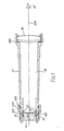
- Part of an aiming aid is a projector 10 (Figure 1) which is arranged to provide a projection of a graticule 11 viewable from a sighting position 12.
- a graticule pattern (not shown) is formed on a surface 14 of graticule 11 for example by printing onto glass.
- the graticule 11 is externally illuminated by ambient light falling upon a ground glass plate 15 so that it may be viewed as aforesaid.
- the light from the graticule 11 is collimated by a lens doublet 16, focussed at the graticule pattern position, so that an image thereof appears at infinity.
- the projector is conveniently of a generally cylindrical form, comprising a barrel portion 17.
- Graticule 11 is mounted, for example by bonding, upon a flanged carrier member 18, which is moveable within the barrel 17.
- carrier position is first fixed horizontally fore and aft between retaining annuli 19 and 100 so that a focussed image of the graticule 11 is viewable from sighting position 12.
- Carrier member 18 is fixed in the vertical plane by means of four set screws in opposing normal pairs, such as set screws 101 and 102. The screws are adjusted such that a reference point on the graticule image appears precisely upon centre-line 103 and then secured in position.
- the assembly is closed by a cap 104 which also serves to retain ground glass plate 15.
- the structure is sealed against its external environment by virtue of two 'O'-ring seals 105, 106.
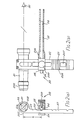
- a weapon aiming aid 20 ( Figure 2), has a projector 21 of the type described above.
- the projector serves to provide a collimated image of a graticule viewable from a sighting position 22.
- the position of the image with respect to the weapon is defined by an extension arm 23, affixed to the projector and arranged to extend in use vertically from the projector 21, and a spigot 24 clamped thereto and adapted to enter the barrel 25 of the weapon.
- the graticule 26 projected by the projector 21 is fixed in a known position by virtue of the clamping of spigot 24 by extension arm 23, which carries slots, such as slot 27 to precisely locate the extension arm 23 with respect to the spigot 24 and thereby with respect to the weapon barrel 26.
- the spigot clamp takes the form of a yoke 28 carrying an end stop 29 and a clamping screw 200 which serves to grip the spigot 24.
- groove 201 serves to precisely locate the height of the graticule 26 with respect to the weapon such that centre line 202 of projector 21 is at a known positional height h above the weapon barrel 25, being that height which when sighted placed reference marker 203 at the weapon boresight. It will further be appreciated that by providing a plurality of slots along the extension arm 23, a plurality of precisely defined positional heights, being those heights appropriate to place reference marks 203 as aforesaid at weapon boresight of a plurality of different weapon types. Clamp yoke 29 may be easily positioned adjacent each of the slots by virtue of engagement of a sprung ball bearing (not ⁇ shown) with a guidance slot formed in an edge of extension member 23, such as guide slot 204 of slot 27. It will thus be apparent that with a single piece of apparatus zeroing of a plurality of different weapon types may be achieved
- spigots of different diameters to co-operate with barrels of different bores may be provided.
- end cap 205 of projector is adapted to receive and locate a source of illumination, such as for example a beta-light torch.
- a typical kit carried to allow zeroing in accordance with the present invention might therefore comprise a projector and extension arm assembly, spigots of different bore and an illumination source for night use. Because such a kit is essentially universal, it need not be carried individually; one kit between a group of marksmen being sufficient, even if they carry different weapon types.
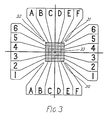
- the projected graticule pattern 30 ( Figure 3) comprises a coarse grid portion 31 formed as a grid of squares and a fine grid portion formed as a plurality of crosses, such as cross 32, one cross formed within each square of coarse grid portion 31.
- the squares of the coarse grid portion 31 may be identified by labels A to F and 1 to 6 marked as eastings and northings respectively, the graticules 30 also comprises a centrally disposed marker 33.
- the size of graticule 20 when projected is arranged such that the labels, coarse grid 30 and reference marker 33 are visible to the un-aided eye to permit use with an iron sight, whereas the finer grid portion is visible with a telescope sight or other magnifying sight.
- each coarse grid square might be such as to subtend 1/milli-radian and each square formed by virtue of the crosses might therefore subtend a half milli-radian.
- This provides resolutions of 100mm and 50mm at a typical firing range distance of 100m as would be appropriate to an iron sight and a times four telescope sight.
- the apparatus of the present invention can be used to zero a weapon, the compensation required by a particular marksman for the weapon type of interest must be established. To achieve this, the marksman may proceed as follows.
- the clamp 28 ( Figure 2) of zeroing device 20 is moved adjacent the slot appropriate to the weapon type of interest until the ball stop engages.
- the spigot 24 appropriate to the weapon bore is selected and clamped in position in slot 201 by means of clamp 28, and is made to enter barrel 25 such that the device is supported.
- extension arm 23 is vertically aligned it will be apparent that the projector 21 and hence graticule reference mark 203 are at a precise distance h above the barrel 25. It has been found that the device is insensitive to small errors of vertical alignment and a simple clip (not shown), is sufficient to maintain a sufficient degree of vertical alignment.
- the clip is preferably of the form which attaches to fire shroud 26 rather than barrel 25. In any event clamping to the barrel which may cause undesirable loading and distortion should be avoided.
- the spigot rod 24 ensures that the projection of the graticule is parallel with the axis of the weapon barrel and the height h is chosen to ensure that the projection will be visible within the field of view of the weapon's sight (not shown).
- the marksman then proceeds to boresight his weapon by sighting reference mark 203.
- the sighting device is now removed from the weapon and the weapon zeroed, for example by the known method of firing at a range target, assessing the fall of shot and adjusting and readjusting the sight until rounds hit where aimed. Following zeroing, the zeroing device is replaced on the weapon and the projected graticule viewed. Generally the sight will now be at a position away from the reference mark, which defines a predetermined position at which the weapon is zeroed.
- the position may be identified by means of the grid.
- For an iron sight reference will be up to coarse grid portion 31, "A6” for example being the top right hand corner. With a magnifying sight reference will be resolved by the finer grid portion 32, "A6 upper left” now being a reference to the top left hand corner. By recalling this reference the marksman may now zero any weapon of the same type by use of the zeroing device alone.
- the device is fitted to the unzeroed weapon, in the way described above, so that the graticule is at a known position with respect to the weapon.
- the graticule is sighted, and the sight adjusted to a predetermined position by recalling the reference established as described above.
- the weapon has now been quickly, simply and covertly zeroed dry; that is without firing a round. The need for a firing range has been avoided.
- the device may be positioned on a weapon, the graticule sighted and the sight position noted. The clamp may then be released and the spigot rod rotated a fraction of a turn, for example half a turn. Re-sighting should not result in a changed sighted position. If there is a change the rod is damaged and should be discarded.
- Parts of the device 20 are preferably fabricated where possible in light robust material, for example aluminium. Weight may be reduced by cut-outs and drillings, for example cut out 207 ( Figure 2). Thus load on the weapon barrel is minimized.
- lens doublet 16 ( Figure 1) may be formed of materials having a temperature/refractive index characteristic selected to compensate for any such errors.
Landscapes
- Physics & Mathematics (AREA)
- Optics & Photonics (AREA)
- Engineering & Computer Science (AREA)
- General Engineering & Computer Science (AREA)
- Aiming, Guidance, Guns With A Light Source, Armor, Camouflage, And Targets (AREA)
- Telescopes (AREA)
Applications Claiming Priority (2)
| Application Number | Priority Date | Filing Date | Title |
|---|---|---|---|
| GB08621245A GB2194621A (en) | 1986-09-03 | 1986-09-03 | Weapon aiming |
| GB8621245 | 1986-09-03 |
Publications (2)
| Publication Number | Publication Date |
|---|---|
| EP0262811A2 true EP0262811A2 (de) | 1988-04-06 |
| EP0262811A3 EP0262811A3 (de) | 1989-03-08 |
Family
ID=10603617
Family Applications (1)
| Application Number | Title | Priority Date | Filing Date |
|---|---|---|---|
| EP87307764A Withdrawn EP0262811A3 (de) | 1986-09-03 | 1987-09-03 | Gerät zur Einstellung der Visiervorrichtung an Feuerwaffen |
Country Status (3)
| Country | Link |
|---|---|
| EP (1) | EP0262811A3 (de) |
| JP (1) | JPS63135792A (de) |
| GB (1) | GB2194621A (de) |
Families Citing this family (3)
| Publication number | Priority date | Publication date | Assignee | Title |
|---|---|---|---|---|
| US5222302A (en) * | 1991-05-10 | 1993-06-29 | Debatty W Marion | Firearm sights aligner |
| US5442860A (en) * | 1993-07-15 | 1995-08-22 | Palmer; Michael R. | Portable reticle alingment device for firearms |
| US6176019B1 (en) | 1998-07-24 | 2001-01-23 | Walter F. Frear, Jr. | Collimator mounting apparatus for bore sighting a firearm |
Family Cites Families (5)
| Publication number | Priority date | Publication date | Assignee | Title |
|---|---|---|---|---|
| GB597401A (en) * | 1943-12-03 | 1948-01-26 | Glenn L Martin Co | Improvements in or relating to sighting means for testing gun alignments |
| US2548700A (en) * | 1946-02-26 | 1951-04-10 | North American Aviation Inc | Bore sighting apparatus |
| DE2166277A1 (de) * | 1970-10-10 | 1973-08-02 | Tasco Sales | In den lauf einer feuerwaffe einschiebbare vorrichtung zum ausrichten eines zielfernrohres |
| US3908282A (en) * | 1974-03-18 | 1975-09-30 | Walter J Steffan | Sighting in apparatus for rifle mounted telescope gunsights |
| DE2543315A1 (de) * | 1975-09-16 | 1977-04-07 | Walter J Steffan | Justiervorrichtung fuer zielfernrohr- gewehre |
-
1986
- 1986-09-03 GB GB08621245A patent/GB2194621A/en not_active Withdrawn
-
1987
- 1987-09-03 JP JP22118387A patent/JPS63135792A/ja active Pending
- 1987-09-03 EP EP87307764A patent/EP0262811A3/de not_active Withdrawn
Also Published As
| Publication number | Publication date |
|---|---|
| GB8621245D0 (en) | 1987-08-19 |
| JPS63135792A (ja) | 1988-06-08 |
| EP0262811A3 (de) | 1989-03-08 |
| GB2194621A (en) | 1988-03-09 |
Similar Documents
| Publication | Publication Date | Title |
|---|---|---|
| US4584776A (en) | Telescopic gun sight | |
| US4403421A (en) | Telescopic gun sight | |
| US4285137A (en) | Trajectory compensating device | |
| US5432598A (en) | Apparatus for laser assisted firearm sights alignment | |
| CN112739973B (zh) | 可调节的反射式瞄准器 | |
| US6453595B1 (en) | Gunsight and reticle therefor | |
| US7712225B2 (en) | Shooting calibration systems and methods | |
| US20120260555A1 (en) | Method and apparatus for alignment of firearm sights | |
| US20050257414A1 (en) | Tactical ranging reticle for a projectile weapon aiming device | |
| DE3853127D1 (de) | Optisches Zielgerät für ein Gewehr. | |
| US20150040409A1 (en) | Bow sight apparatus having multiple lasers | |
| US6609325B2 (en) | Indexing system to aid in the installation of a telescopic sight on a firearm | |
| WO1999030101B1 (en) | Improved gunsight and reticle therefor | |
| US4095347A (en) | Sighting in apparatus for rifle mounted telescope gunsights | |
| US10101124B2 (en) | Scope adapted for short and long range zeroing | |
| US5222302A (en) | Firearm sights aligner | |
| US20180306554A1 (en) | Scope adapted for short and long range zeroing | |
| US6708597B2 (en) | Weapon aiming | |
| US20250035406A1 (en) | Visual targeting apparatus and system | |
| US3475821A (en) | Sub-target aiming device | |
| US20200232765A1 (en) | Scope adapted for short and long range zeroing | |
| EP0262811A2 (de) | Gerät zur Einstellung der Visiervorrichtung an Feuerwaffen | |
| CA1085200A (en) | Sighting device for small arms | |
| US20180328696A1 (en) | System and method for aligning a vertical and/or horizontal reticle of an optical device | |
| US4734990A (en) | Viewing apparatus |
Legal Events
| Date | Code | Title | Description |
|---|---|---|---|
| PUAI | Public reference made under article 153(3) epc to a published international application that has entered the european phase |
Free format text: ORIGINAL CODE: 0009012 |
|
| AK | Designated contracting states |
Kind code of ref document: A2 Designated state(s): AT BE CH DE ES FR GB GR IT LI LU NL SE |
|
| RAP1 | Party data changed (applicant data changed or rights of an application transferred) |
Owner name: SCHLUMBERGER INDUSTRIES LIMITED |
|
| PUAL | Search report despatched |
Free format text: ORIGINAL CODE: 0009013 |
|
| AK | Designated contracting states |
Kind code of ref document: A3 Designated state(s): AT BE CH DE ES FR GB GR IT LI LU NL SE |
|
| STAA | Information on the status of an ep patent application or granted ep patent |
Free format text: STATUS: THE APPLICATION IS DEEMED TO BE WITHDRAWN |
|
| 18D | Application deemed to be withdrawn |
Effective date: 19890909 |