EP0262620A1 - Cleaning cassette for a magnetic-tape apparatus - Google Patents
Cleaning cassette for a magnetic-tape apparatus Download PDFInfo
- Publication number
- EP0262620A1 EP0262620A1 EP87114064A EP87114064A EP0262620A1 EP 0262620 A1 EP0262620 A1 EP 0262620A1 EP 87114064 A EP87114064 A EP 87114064A EP 87114064 A EP87114064 A EP 87114064A EP 0262620 A1 EP0262620 A1 EP 0262620A1
- Authority
- EP
- European Patent Office
- Prior art keywords
- cleaning
- cassette
- drive roller
- cleaning element
- magnetic
- Prior art date
- Legal status (The legal status is an assumption and is not a legal conclusion. Google has not performed a legal analysis and makes no representation as to the accuracy of the status listed.)
- Granted
Links
- 238000004140 cleaning Methods 0.000 title claims abstract description 127
- 239000006260 foam Substances 0.000 claims description 3
- 239000000463 material Substances 0.000 claims description 3
- 238000010073 coating (rubber) Methods 0.000 description 1
- 239000007788 liquid Substances 0.000 description 1
- 239000004033 plastic Substances 0.000 description 1
Images

Classifications
-
- G—PHYSICS
- G11—INFORMATION STORAGE
- G11B—INFORMATION STORAGE BASED ON RELATIVE MOVEMENT BETWEEN RECORD CARRIER AND TRANSDUCER
- G11B23/00—Record carriers not specific to the method of recording or reproducing; Accessories, e.g. containers, specially adapted for co-operation with the recording or reproducing apparatus ; Intermediate mediums; Apparatus or processes specially adapted for their manufacture
- G11B23/02—Containers; Storing means both adapted to cooperate with the recording or reproducing means
- G11B23/04—Magazines; Cassettes for webs or filaments
- G11B23/049—Cassettes for special applications not otherwise provided for
-
- G—PHYSICS
- G11—INFORMATION STORAGE
- G11B—INFORMATION STORAGE BASED ON RELATIVE MOVEMENT BETWEEN RECORD CARRIER AND TRANSDUCER
- G11B5/00—Recording by magnetisation or demagnetisation of a record carrier; Reproducing by magnetic means; Record carriers therefor
- G11B5/41—Cleaning of heads
Definitions
- the invention relates to a cleaning cassette for a magnetic tape device according to the preamble of claim 1.
- Magnetic tape devices are known in which a magnetic tape cassette is used, in which both the tape is moved via a tape drive device and the reel is driven via a rubber band comprising the reels.
- a cleaning cassette for such a magnetic tape device has also already been proposed (European patent application 86104435.2), in which a cleaning device for the magnetic head is driven by the tape drive roller. Since the belt drive roller is used to drive the cleaning device, it cannot be easily cleaned with this cleaning cassette at the same time.
- the invention is therefore based on the object of specifying a cleaning cassette in which the cleaning device for the magnetic head is actuated via the tape drive roller and by means of which cleaning of the tape drive roller is nevertheless possible.
- the cleaning cassette according to the invention has the advantage that it has very good cleaning properties because, depending on the direction in which it is inserted into the magnetic tape device, it specifically cleans either the magnetic head or the tape drive roller.
- the same or the same cleaning element made of a flexible material, such as foam or felt is used both for cleaning the magnetic head and for cleaning the tape drive roller.
- the cleaning element is advantageous to provide with grooves. These grooves can be provided on one side or on two sides of the cleaning element, so that, depending on the application, optimal cleaning of the magnetic head or the tape drive roller is achieved.
- the cleaning element for the tape drive roller can be arranged parallel or perpendicular to the longitudinal wall of the cleaning cassette, which is opposite the side on which the cleaning device for the magnetic head is arranged.
- the cleaning elements are expediently designed to be exchangeable.
- the cleaning elements can be provided with an opening by means of which they can be pushed over a latchable, flexible strip. It is also possible to slide the cleaning element for the belt drive roller in the longitudinal direction into an opening in the cleaning cassette.
- the cleaning cassette 1 shown in FIG. 1 of a first embodiment of the invention has external dimensions which largely correspond to those of a commercially available cassette provided with magnetic tape, which is also known under the name 1/4 inch cartridge.
- the part of the cleaning cassette 1 shown in FIG. 1, which relates to the cleaning of the magnetic head, is described in detail in the European patent application 86104435.2.
- the drive wheel 5 is designed, for example, as a friction wheel and has a rubber coating on its circumference.
- a worm 6 is arranged, for example with the drive wheel 5 Unit forms.
- the worm 6 is part of a worm gear and is assigned to a worm wheel 7 which is arranged on an eccentric arrangement 8.
- the eccentric arrangement 8 is formed from a shaft mounted in bearings 9, on which the worm wheel 7 is also arranged, and an eccentric shaft 11.
- the eccentric shaft 11 is arranged inclined to the axis of the shaft 10 and when the eccentric arrangement 8 rotates, a carrier 12 is set in a to-and-fro movement and at the same time in an oscillating movement, which can also be understood as a pivoting movement or partial rotary movement.
- a carrier 12 is supported at its rear end by a spherical part 15 and engages around the eccentric shaft 11 on one side, for example the top side by means of lateral support surfaces and on the other side, for example the bottom side by a lip 13.
- a pivotable strip 14 can be seen, which is fastened to the carrier 12 via a joint 21. If the carrier is made of plastic, the joint is designed, for example, as a film hinge.
- the strip 14 has at its other end a latching lug 22 which can be inserted into a corresponding opening 23 in the carrier 12.
- the cleaning element 4 which has a corresponding longitudinal opening, is pushed over the strip.
- the cleaning element 4 is interchangeably attached to the strip 14 and, when it is folded out, can simply be exchanged or rotated so that it can be used from both sides.
- the cleaning element 4 is constructed like a pillow or cuboid. It consists of a flexible material such as foam and can be soaked with a cleaning liquid.
- the cassette 1 is inserted into the magnetic tape device in the opposite direction, so that the tape drive roller 3, now shown in solid lines, lies against an associated cleaning element 24.
- This cleaning element 24 is also arranged on a strip 25 which is designed in a similar manner to the strip 14 and also has a latching lug and from the cassette 1 for replacing the cleaning element 24 can be pivoted out as shown in dashed lines.
- the cleaning element 24 and a corresponding opening 26 for the magnetic head are arranged on the side of the cassette 1 opposite the cleaning element 4, so that, depending on the direction in which the cassette 1 is inserted, either the magnetic head or the tape drive roller 3 are cleaned.
- the cassette 1 contains only cutouts 30 in the base plate, which are intended to prevent the cassette from being inserted in the wrong direction. However, since the cassette 1 can now be inserted into the magnetic tape device in both directions, depending on whether the magnetic head or the tape drive roller 3 is to be cleaned, two additional cutouts 31 are provided in the base plate 32.
- the tape drive roller 3 can be driven in both directions of rotation and the tape drive roller 3 is cleaned by contact with the cleaning element 24.
- the cleaning element 24 is designed in the same way as the cleaning element 24 and is likewise attached to a strip 25 with a latching lug. Furthermore, the additional cutouts 31 can be seen in the base plate 32 of the cassette 1.
- the cleaning elements 4 and 24 can have different surfaces. Some exemplary embodiments are shown in FIGS. 3a to 3d.
- the cleaning element 4 or 24 has longitudinal grooves on one side. This side is particularly suitable for cleaning the magnetic head, while the back can be used for cleaning the tape drive roller 3 without the grooves.
- the cleaning element can be attached to the strips 14 or 25 in one or the other direction.
- the cleaning element 4 or 24 is constructed symmetrically, so that it can be attached to the strips 14 or 25 as desired.
- the cleaning element 4 or 24 shown in FIG 3c has oblique grooves and this cleaning element can also be used both for cleaning the magnetic head and for cleaning the tape drive roller 3, wherein the grooves can also be provided on the back and then that Cleaning element can be plugged onto the strips 14 or 25 by means of the longitudinal opening 33.
- the second embodiment of the cleaning cassette 1 shown in FIG. 4 contains the same components for cleaning the magnetic head as the cleaning cassette 1 shown in FIG. 1.
- the cleaning element 24 is arranged perpendicular to the longitudinal wall, so that it is not the long side but the transverse side of the cleaning element 24 cleans the tape drive roller 3.
- the cleaning element 24 is inserted longitudinally into a corresponding opening and resiliently presses against the tape drive roller 3.
- the cleaning element 24 can be identical to the cleaning element 4, which is the cleaning of the magnetic head makes.
Abstract
Die Reinigungskassette weist an ihrer einen Längsseite ein Reinigungselement (4) zum Reinigen eines Magnetkopfs eines Magnetbandgeräts und auf der gegenüberliegenden Längsseite ein Reinigungselement (24) zum Reinigen einer Bandantriebsrolle (3) des Magnetbandgeräts auf. Je nach dem, in welcher Richtung die Reinigungskassette (1) in das Magnetbandgerät eingeführt wird, kommt das eine Reinigungselement (4) mit dem Magnetkopf oder das weitere Reinigungselement (24) mit der Bandantriebsrolle (3) zum Zweck der Reinigung in Berührung. Der Magnetkopf wird durch eine Hin- und Herbewegung des Reinigungselements (4) gereinigt, die über eine Exzenteranordnung (8, 11) durch die Bandantriebsrolle (3) bewirkt wird, während die Reinigung der Bandantriebsrolle (3) beim Einführen der Reinigungskassette (1) in entgegengesetzter Richtung durch die Drehbewegung der Bandantriebsrolle (3) bei feststehendem weiteren Reinigungselement (24) erfolgt.The cleaning cassette has on one long side a cleaning element (4) for cleaning a magnetic head of a magnetic tape device and on the opposite long side a cleaning element (24) for cleaning a tape drive roller (3) of the magnetic tape device. Depending on the direction in which the cleaning cassette (1) is inserted into the magnetic tape device, one cleaning element (4) comes into contact with the magnetic head or the other cleaning element (24) comes into contact with the tape drive roller (3) for the purpose of cleaning. The magnetic head is cleaned by a reciprocating movement of the cleaning element (4), which is effected by the tape drive roller (3) via an eccentric arrangement (8, 11), while the tape drive roller (3) is cleaned when the cleaning cartridge (1) is inserted in opposite direction by the rotary movement of the belt drive roller (3) with a fixed further cleaning element (24).
Description
Die Erfindung bezieht sich auf eine Reinigungskassette für ein Magnetbandgerät gemäß dem Oberbegriff des Patentanspruches 1.The invention relates to a cleaning cassette for a magnetic tape device according to the preamble of claim 1.
Es ist bereits allgemein bekannt, zum Reinigen eines Magnetkopfs und einer Bandantriebsrolle für das Magnetband in einem Magnetbandgerät eine Kassette zu verwenden, die anstelle einer mit dem Magnetband versehenen Kassette in das Magnetbandgerät eingeführt wird. Anstelle des Magnetbands enthalten diese Reinigungskassetten Reinigungseinrichtungen für den Magnetkopf und gegebenenfalls auch für eine das Magnetband antreibende Bandantriebsrolle. Derartige Reinigungskassetten sind beispielsweise aus der US-PS 4,445,158 oder der US-PS 4,272,796 bekannt. Bei diesen bekannten Reinigungskassetten wird die Reingigungseinrichtung für den Magnetkopf jeweils von einer Antriebsanordnung angetrieben, die normalerweise die Spulen mit dem Magnetband in der Magnetbandkassette antreiben. Damit ist es möglich, gleichzeitig den Magnetkopf und die Bandantriebsrolle zu reinigen und die Reinigungselemente für den Magnetkopf und die Bandantriebsrolle befinden sich nebeneinander an derselben Seite der Magnetbandkassette.It is already generally known to use a cassette for cleaning a magnetic head and a tape drive roller for the magnetic tape in a magnetic tape device which is inserted into the magnetic tape device instead of a cassette provided with the magnetic tape. Instead of the magnetic tape, these cleaning cassettes contain cleaning devices for the magnetic head and possibly also for a tape drive roller driving the magnetic tape. Cleaning cartridges of this type are known, for example, from US Pat. No. 4,445,158 or US Pat. No. 4,272,796. In these known cleaning cassettes, the cleaning device for the magnetic head is each driven by a drive arrangement which normally drives the reels with the magnetic tape in the magnetic tape cassette. This makes it possible to clean the magnetic head and the tape drive roller at the same time, and the cleaning elements for the magnetic head and the tape drive roller are located next to one another on the same side of the magnetic tape cassette.
Es sind Magnetbandgeräte bekannt, bei denen eine Magnetbandkassette verwendet wird, bei der über eine Bandantriebseinrichtung sowohl das Band bewegt wird als auch über ein die Spulen umfassendes Gummiband die Spule angetrieben werden. Es wurde auch bereits eine Reinigungskassette für ein derartiges Magnetbandgerät vorgeschlagen (europäische Patentanmeldung 86104435.2), bei der eine Reinigungseinrichtung für den Magnetkopf durch die Bandantriebsrolle angetrieben wird. Da die Bandantriebsrolle zum Antrieb der Reinigungseinrichtung verwendet wird, ist ihre gleichzeitige Reinigung mit dieser Reinigungskassette nicht ohne weiteres möglich.Magnetic tape devices are known in which a magnetic tape cassette is used, in which both the tape is moved via a tape drive device and the reel is driven via a rubber band comprising the reels. A cleaning cassette for such a magnetic tape device has also already been proposed (European patent application 86104435.2), in which a cleaning device for the magnetic head is driven by the tape drive roller. Since the belt drive roller is used to drive the cleaning device, it cannot be easily cleaned with this cleaning cassette at the same time.
Der Erfindung liegt daher die Aufgabe zugrunde, eine Reinigungskassette anzugeben, bei der die Reinigungseinrichtung für den Magnetkopf über die Bandantriebsrolle betätigt wird und mittels der dennoch eine Reinigung der Bandantriebsrolle möglich ist.The invention is therefore based on the object of specifying a cleaning cassette in which the cleaning device for the magnetic head is actuated via the tape drive roller and by means of which cleaning of the tape drive roller is nevertheless possible.
Erfindungsgemäß wird die Aufgabe bei der Reinigungskassette der eingangs genannten Art durch die im kennzeichnenden Teil des Patentanspruchs 1 angegebenen Merkmale gelöst.According to the invention the object is achieved in the cleaning cassette of the type mentioned by the features specified in the characterizing part of patent claim 1.
Die Reinigungskassette gemäß der Erfindung hat den Vorteil, daß sie sehr gute Reinigungseigenschaften aufweist, da sie, je nach dem in welcher Richtung sie in das Magnetbandgerät eingeführt wird, gezielt entweder den Magnetkopf oder die Bandantriebsrolle reinigt.The cleaning cassette according to the invention has the advantage that it has very good cleaning properties because, depending on the direction in which it is inserted into the magnetic tape device, it specifically cleans either the magnetic head or the tape drive roller.
Zweckmäßigerweise wird sowohl für die Reinigung des Magnetkopfs als auch für die Reinigung der Bandantriebsrolle ein gleiches oder dasselbe Reinigungselement aus einem flexiblen Werkstoff, wie beispielsweise Schaumstoff oder Filz verwendet. Zum Beseitigen der Ablagerungen ist es dabei günstig, das Reinigungselement mit Rillen zu versehen. Diese Rillen können an einer Seite oder an zwei Seiten des Reinigungselements vorgesehen werden, so daß je nach Anwendungsfall eine optimale Reinigung des Magnetkopfs bzw. der Bandantriebsrolle erreicht wird. Das Reinigungselement für die Bandantriebsrolle kann parallel oder senkrecht zu der Längswand der Reinigungskassette angeordnet werden, die der Seite gegenüberliegt, an der die Reinigungseinrichtung für den Magnetkopf angeordnet ist.Expediently, the same or the same cleaning element made of a flexible material, such as foam or felt, is used both for cleaning the magnetic head and for cleaning the tape drive roller. To remove the deposits, it is advantageous to provide the cleaning element with grooves. These grooves can be provided on one side or on two sides of the cleaning element, so that, depending on the application, optimal cleaning of the magnetic head or the tape drive roller is achieved. The cleaning element for the tape drive roller can be arranged parallel or perpendicular to the longitudinal wall of the cleaning cassette, which is opposite the side on which the cleaning device for the magnetic head is arranged.
Die Reinigungselemente werden zweckmäßigerweise auswechselbar ausgebildet. Die Reinigungselemente können zu diesem Zweck mit einer Öffnung versehen sein, mittels der sie über einen verrastbaren flexiblen Streifen gesteckt werden können. Es ist auch möglich, das Reinigungselement für die Bandantriebsrolle in Längsrichtung in eine Öffnung der Reinigungskassette hineinzuschieben.The cleaning elements are expediently designed to be exchangeable. For this purpose, the cleaning elements can be provided with an opening by means of which they can be pushed over a latchable, flexible strip. It is also possible to slide the cleaning element for the belt drive roller in the longitudinal direction into an opening in the cleaning cassette.
Ausführungsbeispiele der Reinigungskassette gemäß der Erfindung werden im folgenden anhand von Zeichnungen näher erläutert. Es zeigen
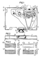
- FIG 1 eine teilweise aufg ebrochene Draufsicht auf eine erste Ausführungsform der Reinigungskassette,
- FIG 2 eine Seitenansicht der in FIG 1 dargestellten Reinigungskassette,
- FIG 3 verschiedene Ausführungsformen von Reinigungselementen,
- FIG 4 eine teilweise aufgebrochene Draufsicht einer zweiten Ausführungsform der Reinigungskassette und
- FIG 5 eine Seitenansicht der in FIG 4 dargestellten Reinigungskassette.
- 1 shows a partially broken plan view of a first embodiment of the cleaning cassette,
- 2 shows a side view of the cleaning cassette shown in FIG. 1,
- 3 different embodiments of cleaning elements,
- 4 shows a partially broken top view of a second embodiment of the cleaning cassette and
- 5 shows a side view of the cleaning cassette shown in FIG.
Die in FIG 1 dargestellte Reinigungskassette 1 einer ersten Ausführungsform der Erfindung weist äußere Abmessungen auf, die denen einer im Handel erhältlichen mit Magnetband versehenen Kassette, die auch unter der Bezeichnung 1/4-Inch-Cartridge bekannt ist, weitgehend entsprechen. Der Teil, der in FIG 1 dargestellten Reinigungskassette 1, der die Reinigung des Magnetkopfs betrifft, ist in der europäischen Patentanmeldung 86104435.2 ausführlich beschrieben. Nach dem Einführen der Kassette 1 in ein entsprechendes Magnetbandgerät mit einem Magnetkopf und einer normalerweise für den Antrieb des Magnetbands vorgesehenen Bandantriebsrolle 3 derart, daß die Frontseite eines nicht dargestellten Magnetkopfs an einem Reinigungselement 4 einer in der Kassette 1 enthaltenen Reinigungseinrichtung anliegt und eine gestrichelt dargestellte Bandantriebsrolle 3 an einem Antriebsrad 5 der Kassette 1 anliegt. Das Antriebsrad 5 ist beispielsweise als Reibrad ausgebildet und enthält an seinem Umfang eine Beschichtung aus Gummi. Auf der Achse des Antriebsrads 5 ist eine Schnecke 6 angeordnet, die beispielsweise mit dem Antriebsrad 5 eine Baueinheit bildet. Die Schnecke 6 ist Teil eines Schneckengetriebes und ist einem Schneckenrad 7 zugeordnet, das auf einer Exzenteranordnung 8 angeordnet ist. Die Exzenteranordnung 8 wird aus einer in Lagern 9 gelagerten Welle, auf der auch das Schneckenrad 7 angeordnet ist und einer Exzenterwelle 11 gebildet.The cleaning cassette 1 shown in FIG. 1 of a first embodiment of the invention has external dimensions which largely correspond to those of a commercially available cassette provided with magnetic tape, which is also known under the name 1/4 inch cartridge. The part of the cleaning cassette 1 shown in FIG. 1, which relates to the cleaning of the magnetic head, is described in detail in the European patent application 86104435.2. After inserting the cassette 1 into a corresponding magnetic tape device with a magnetic head and a
Die Exzenterwelle 11 ist gegen die Achse der Welle 10 geneigt angeordnet und bei einer Drehung der Exzenteranordnung 8 wird ein Träger 12 in eine Hin- und Herbewegung und gleichzeitig in eine Schwingbewegung, die auch als eine Schwenkbewegung oder teilweise Drehbewegung aufgefaßt werden kann, versetzt. Ein Träger 12 ist an seinem hinteren Ende durch ein kugelförmiges Teil 15 gelagert und umgreift die Exzenterwelle 11 auf der einen Seite, beispielsweise der Oberseite durch seitliche Auflageflächen und auf der anderen Seite, beispielsweise der Unterseite durch eine Lippe 13. An der Vorderseite des Trägers ist ein schwenkbarer Streifen 14 zu erkennen, der über ein Gelenk 21 am Träger 12 befestigt ist. Wenn der Träger aus Kunststoff ausgebildet ist, ist das Gelenk beispielsweise als Filmscharnier ausgebildet. Der Streifen 14 weist an seinem anderen Ende eine Rastnase 22 auf, die in eine entsprechende Öffnung 23 des Trägers 12 einschiebbar ist. Über den Streifen wird das Reinigungselement 4 geschoben, das eine entsprechende Längsöffnung aufweist. Das Reinigungselement 4 ist auswechselbar auf dem Streifen 14 befestigt und kann, wenn dieser herausgeklappt ist, einfach ausgetauscht oder gedreht werden, so daß es von beiden Seiten benutzt werden kann. Das Reinigungselement 4 ist kissen- oder quaderförmig aufgebaut. Es besteht aus einem flexiblen Werkstoff, beispielsweise Schaumstoff und kann mit einer Reinigungsflüssigkeit getränkt werden.The eccentric shaft 11 is arranged inclined to the axis of the shaft 10 and when the
Zum Reinigen der Bandantriebsrolle 3 wird die Kassette 1 in der entgegengesetzten Richtung in das Magnetbandgerät eingeführt, so daß die nun durchgezogen dargestellte Bandantriebsrolle 3 an einem zugehörigen Reinigungselement 24 anliegt, das in gleicher Weise ausgebildet sein kann, wie das Reinigungselement 4. Auch dieses Reinigungselement 24 ist auf einem Streifen 25 angeordnet, der in ähnlicher Weise ausgebildet ist, wie der Streifen 14 und ebenfalls eine Rastnase aufweist und aus der Kassette 1 zum Auswechseln des Reinigungselements 24 herausgeschwenkt werden kann, wie es gestrichelt dargestellt ist. Das Reinigungselement 24 und eine entsprechende Öffnung 26 für den Magnetkopf sind auf der dem Reinigungselement 4 gegenüberliegenden Seite der Kassette 1 angeordnet, so daß, je nach dem in welcher Richtung die Kassette 1 eingeführt wird, entweder der Magnetkopf oder die Bandantriebsrolle 3 gereinigt werden. Normalerweise enthält die Kassette 1 nur Ausschnitte 30 in der Grundplatte, mit denen ein Einführen der Kassette in der falschen Richtung verhindert werden soll. Da nun aber die Kassette 1 in beiden Richtungen in das Magnetbandgerät eingeführt werden kann, je nach dem ob der Magnetkopf oder die Bandantriebsrolle 3 gereinigt werden sollen, werden zwei zusätzliche Ausschnitte 31 in der Grundplatte 32 vorgesehen.To clean the
Wenn die Kassette 1 in das Magnetbandgerät eingeführt ist und die Bandantriebsrolle 3 das Reinigungselement 4 berührt, kann die Bandantriebsrolle 3 in beiden Drehrichtungen angetrieben werden und durch die Berührung mit dem Reinigungselement 24 wird die Bandantriebsrolle 3 gereinigt.When the cassette 1 is inserted into the magnetic tape device and the
Bei der in FIG 2 dargestellten Seitenansicht ist zu erkennen, daß das Reinigungselemente 24 in gleicher Weise ausgebildet ist wie das Reinigungselement 24 und ebenfalls auf einen Streifen 25 mit einer Rastnase aufgesteckt ist. Weiterhin sind die zusätzlichen Ausschnitte 31 in der Grundplatte 32 der Kassette 1 zu erkennen.In the side view shown in FIG. 2 it can be seen that the
Die Reinigungselemente 4 und 24 können unterschiedliche Oberflächen aufweisen. Einige Ausführungsbeispiele sind in den FIG 3a bis 3d dargestellt.The
Bei der in FIG 3a dargestellten Ausführungsform weist das Reinigungselement 4 bzw. 24 auf einer Seite Längsrillen auf. Diese Seite eignet sich insbesondere für die Reinigung des Magnetkopfs, während für die Reinigung der Bandantriebsrolle 3 die Rückseite ohne die Rillen verwendet werden kann. Zu diesem Zweck kann das Reinigungselement auf den Streifen 14 oder 25 in der einen oder in der anderen Richtung aufgesteckt werden.In the embodiment shown in FIG. 3a, the
Bei der Darstellung in FIG 3b ist das Reinigungselement 4 bzw. 24 symmetrisch aufgebaut, so daß es beliebig auf die Streifen 14 bzw. 25 aufgesteckt werden kann.In the illustration in FIG. 3b, the
Das in FIG 3c dargestellte Reinigungselement 4 bzw. 24 weist schräg verlaufende Rillen auf und dieses Reinigungselement kann ebenfalls sowohl für die Reinigung des Magnetkopfs als auch für die Reinigung der Bandantriebsrolle 3 verwendet werden, wobei auch auf der Rückseite die Rillen vorgesehen werden können und dann das Reinigungselement mittels der Längsöffnung 33 beliebig auf die Streifen 14 bzw. 25 aufgesteckt werden kann.The
Entsprechendes gilt für das in FIG 3d dargestellte Reinigungselement 4 bzw. 24, bei dem die Rillen rautenförmig auf beiden Seiten angeordnet sind.The same applies to the
Die in FIG 4 dargestellte zweite Ausführungsform der Reinigungskassette 1 enthält für die Reinigung des Magnetkopfs dieselben Bauteile wie die in FIG 1 dargestellte Reinigungskassette 1. Zur Reinigung der Bandantriebsrolle 3 ist jedoch das Reinigungselement 24 senkrecht zur Längswand angeordnet, so daß nicht die Längsseite sondern die Querseite des Reinigungselements 24 die Bandantriebsrolle 3 reinigt. Das Reinigungselement 24 ist längs in eine entsprechende Öffnung eingeschoben und drückt federnd gegen die Bandantriebsrolle 3. Auch hier kann das Reinigungselement 24 mit dem Reinigungselement 4 identisch sein, das die Reinigung des Magnetkopfs vornimmt. Es ist jedoch auch möglich, andere Reinigungselemente für die Reinigung der Bandantriebsrolle 3 zu verwenden.The second embodiment of the cleaning cassette 1 shown in FIG. 4 contains the same components for cleaning the magnetic head as the cleaning cassette 1 shown in FIG. 1. However, for cleaning the
Bei der in FIG 5 dargestellten Seitenansicht der Kassette 1 ist zu erkennen, daß das Reinigungselement 24 der Länge nach in die Öffnung 34 eingeschoben ist. Auch bei dieser Kassette 1 sind Ausschnitte 31 in der Grundplatte 32 vorgesehen, um die Kassette 1 wahlweise in der einen oder der entgegengesetzten Richtung in das Magnetbandgerät einführen zu können. In the side view of the cassette 1 shown in FIG. 5 it can be seen that the
Claims (11)
Applications Claiming Priority (2)
| Application Number | Priority Date | Filing Date | Title |
|---|---|---|---|
| DE3633221 | 1986-09-30 | ||
| DE19863633221 DE3633221A1 (en) | 1986-09-30 | 1986-09-30 | CLEANING CASSETTE FOR A MAGNETIC TAPE DEVICE |
Publications (2)
| Publication Number | Publication Date |
|---|---|
| EP0262620A1 true EP0262620A1 (en) | 1988-04-06 |
| EP0262620B1 EP0262620B1 (en) | 1991-11-21 |
Family
ID=6310689
Family Applications (1)
| Application Number | Title | Priority Date | Filing Date |
|---|---|---|---|
| EP87114064A Expired - Lifetime EP0262620B1 (en) | 1986-09-30 | 1987-09-25 | Cleaning cassette for a magnetic-tape apparatus |
Country Status (4)
| Country | Link |
|---|---|
| US (1) | US4763216A (en) |
| EP (1) | EP0262620B1 (en) |
| JP (1) | JPH0792904B2 (en) |
| DE (2) | DE3633221A1 (en) |
Cited By (2)
| Publication number | Priority date | Publication date | Assignee | Title |
|---|---|---|---|---|
| WO1988010496A1 (en) * | 1987-06-23 | 1988-12-29 | Automation Facilities Limited | Cleaning cassette |
| FR2633431A1 (en) * | 1988-05-10 | 1989-12-29 | Allsop Inc | APPARATUS FOR PERFORMING A CLEANING OPERATION ON A MACHINE RECEIVING MAGNETIC TAPE DATA AND / OR RECORDING DATA THEREON |
Families Citing this family (6)
| Publication number | Priority date | Publication date | Assignee | Title |
|---|---|---|---|---|
| US5012376A (en) * | 1987-10-14 | 1991-04-30 | Pericomp Corporation | Tape head cleaner cartridge having a mesh cleaning layer |
| US5420737A (en) * | 1994-06-14 | 1995-05-30 | Allsop, Inc. | Cleaning apparatus for a tape drive machine with a mechanism to select between a capstan cleaning configuration and a head cleaning configuration |
| US5671108A (en) * | 1995-08-29 | 1997-09-23 | Allsop, Inc. | Tape drive cleaner |
| IES960003A2 (en) * | 1996-01-04 | 1997-07-02 | Joseph Frederick Fritsch | A treatment device |
| US6021026A (en) * | 1998-04-08 | 2000-02-01 | Storage Technology Corporation | Cleaning cartridge |
| US6762912B2 (en) * | 2001-04-10 | 2004-07-13 | Iomega Corporation | Head cleaner for a disk drive into which a disk media cartridge is inserted |
Citations (9)
| Publication number | Priority date | Publication date | Assignee | Title |
|---|---|---|---|---|
| US3439922A (en) * | 1967-12-19 | 1969-04-22 | Sheldon Howard | Cleaner cartridge |
| US3761994A (en) * | 1972-02-01 | 1973-10-02 | A Becht | Magnetic tape head cleaning apparatus |
| GB2000623A (en) * | 1977-06-30 | 1979-01-10 | Allsop Automatic | Cleaner for tape-cassette player |
| US4141053A (en) * | 1977-07-18 | 1979-02-20 | Stephen Kara | Magnetic tape head cleaning apparatus |
| US4272796A (en) * | 1979-06-29 | 1981-06-09 | Kraco Enterprises, Inc. | Automatic cassette cleaner |
| DE3300418A1 (en) * | 1982-01-07 | 1983-07-14 | Allsop Inc., 98225 Bellingham, Wash. | CLEANING HEAD FOR A CASSETTE CLEANER |
| US4470089A (en) * | 1981-12-21 | 1984-09-04 | International Jensen Incorporated | Tape unit cleaning device |
| US4514777A (en) * | 1983-05-09 | 1985-04-30 | Teac Corporation | Device for cleaning the magnetic head of a recorder/reproducer apparatus for use with a magnetic tape cartridge or the like |
| EP0198318A1 (en) * | 1985-04-02 | 1986-10-22 | Tandberg Data A/S | Magnetic head cleaning system in a magnetic tape apparatus |
Family Cites Families (3)
| Publication number | Priority date | Publication date | Assignee | Title |
|---|---|---|---|---|
| JPS5333230Y2 (en) * | 1971-04-20 | 1978-08-16 | ||
| JPS58169320A (en) * | 1982-03-31 | 1983-10-05 | Pioneer Electronic Corp | Cassette for head cleaning |
| DE3245877A1 (en) * | 1982-12-11 | 1984-06-14 | Thomas H. Blank | CLEANING CASSETTE |
-
1986
- 1986-09-30 DE DE19863633221 patent/DE3633221A1/en not_active Withdrawn
-
1987
- 1987-08-14 US US07/085,371 patent/US4763216A/en not_active Expired - Fee Related
- 1987-09-25 DE DE8787114064T patent/DE3774658D1/en not_active Expired - Lifetime
- 1987-09-25 EP EP87114064A patent/EP0262620B1/en not_active Expired - Lifetime
- 1987-09-30 JP JP62244451A patent/JPH0792904B2/en not_active Expired - Lifetime
Patent Citations (9)
| Publication number | Priority date | Publication date | Assignee | Title |
|---|---|---|---|---|
| US3439922A (en) * | 1967-12-19 | 1969-04-22 | Sheldon Howard | Cleaner cartridge |
| US3761994A (en) * | 1972-02-01 | 1973-10-02 | A Becht | Magnetic tape head cleaning apparatus |
| GB2000623A (en) * | 1977-06-30 | 1979-01-10 | Allsop Automatic | Cleaner for tape-cassette player |
| US4141053A (en) * | 1977-07-18 | 1979-02-20 | Stephen Kara | Magnetic tape head cleaning apparatus |
| US4272796A (en) * | 1979-06-29 | 1981-06-09 | Kraco Enterprises, Inc. | Automatic cassette cleaner |
| US4470089A (en) * | 1981-12-21 | 1984-09-04 | International Jensen Incorporated | Tape unit cleaning device |
| DE3300418A1 (en) * | 1982-01-07 | 1983-07-14 | Allsop Inc., 98225 Bellingham, Wash. | CLEANING HEAD FOR A CASSETTE CLEANER |
| US4514777A (en) * | 1983-05-09 | 1985-04-30 | Teac Corporation | Device for cleaning the magnetic head of a recorder/reproducer apparatus for use with a magnetic tape cartridge or the like |
| EP0198318A1 (en) * | 1985-04-02 | 1986-10-22 | Tandberg Data A/S | Magnetic head cleaning system in a magnetic tape apparatus |
Non-Patent Citations (1)
| Title |
|---|
| PATENT ABSTRACTS OF JAPAN, Band 8, Nr. 165 (P-291)[1602], 31. Juli 1984; & JP-A-59 60 727 (FUJITSU K.K.) 06-04-1984 * |
Cited By (3)
| Publication number | Priority date | Publication date | Assignee | Title |
|---|---|---|---|---|
| WO1988010496A1 (en) * | 1987-06-23 | 1988-12-29 | Automation Facilities Limited | Cleaning cassette |
| US5021911A (en) * | 1987-06-23 | 1991-06-04 | Automation Facilities Limited | Cleaning cassette |
| FR2633431A1 (en) * | 1988-05-10 | 1989-12-29 | Allsop Inc | APPARATUS FOR PERFORMING A CLEANING OPERATION ON A MACHINE RECEIVING MAGNETIC TAPE DATA AND / OR RECORDING DATA THEREON |
Also Published As
| Publication number | Publication date |
|---|---|
| DE3633221A1 (en) | 1988-03-31 |
| JPS6391819A (en) | 1988-04-22 |
| EP0262620B1 (en) | 1991-11-21 |
| DE3774658D1 (en) | 1992-01-02 |
| JPH0792904B2 (en) | 1995-10-09 |
| US4763216A (en) | 1988-08-09 |
Similar Documents
| Publication | Publication Date | Title |
|---|---|---|
| EP0110349B1 (en) | Arrangement for positioning a magnetic head on several tape tracks | |
| DE2758790C2 (en) | ||
| DE10228996A1 (en) | Cover film transfer device and method for replacing cover film transfer tapes | |
| DE2828964A1 (en) | CLEANING DEVICE FOR CASSETTE TAPE DEVICES | |
| EP0028708B1 (en) | Cleaning cassette for cassette recorder | |
| DE2636169C3 (en) | Magnetic tape cassette | |
| EP0262620B1 (en) | Cleaning cassette for a magnetic-tape apparatus | |
| DE2853129A1 (en) | DRUM SCRAPER BLADE FOR AN ELECTROPHOTOGRAPHIC COPIER | |
| EP0198318B1 (en) | Magnetic head cleaning system in a magnetic tape apparatus | |
| DE2427690C3 (en) | Holder for a blade that acts on a rigid roller surface | |
| DE2844566C2 (en) | Magnetic recording and reproducing device for magnetic tape cassettes of various sizes | |
| DE1948636C3 (en) | Multi-track magnetic head arrangement | |
| DE3409192A1 (en) | DOUBLE-USE HEAD CLEANER FOR FLOPPY DISC DRIVES | |
| DE2608504A1 (en) | CASSETTE RECORDER OR PLAYER | |
| DE3034923C2 (en) | Ribbon printing unit | |
| DE3915167A1 (en) | CLEANING DEVICE FOR TAPE DEVICES | |
| DE1933295B2 (en) | Tape guide arrangement for a video magnetic tape recorder | |
| DE3043684C2 (en) | Print head with a number of rotatable wheels | |
| DE19634608A1 (en) | Read/write head cleaning device for audio or video tape player | |
| DE2832557C3 (en) | Case for a magnetic tape cassette | |
| DE2705328B2 (en) | Covering device for covering the nozzles in an ink pen | |
| EP0573789A2 (en) | Device for storing magnetic tape cassettes | |
| DE3244165A1 (en) | Magnetic tape apparatus | |
| DE3043683A1 (en) | ADJUSTABLE PRINTING DEVICE AND METHOD FOR THE PRODUCTION THEREOF | |
| DE2556552C3 (en) | Finger toothbrush |
Legal Events
| Date | Code | Title | Description |
|---|---|---|---|
| PUAI | Public reference made under article 153(3) epc to a published international application that has entered the european phase |
Free format text: ORIGINAL CODE: 0009012 |
|
| AK | Designated contracting states |
Kind code of ref document: A1 Designated state(s): DE GB |
|
| 17P | Request for examination filed |
Effective date: 19880830 |
|
| 17Q | First examination report despatched |
Effective date: 19900515 |
|
| GRAA | (expected) grant |
Free format text: ORIGINAL CODE: 0009210 |
|
| AK | Designated contracting states |
Kind code of ref document: B1 Designated state(s): DE GB |
|
| REF | Corresponds to: |
Ref document number: 3774658 Country of ref document: DE Date of ref document: 19920102 |
|
| GBT | Gb: translation of ep patent filed (gb section 77(6)(a)/1977) | ||
| PLBE | No opposition filed within time limit |
Free format text: ORIGINAL CODE: 0009261 |
|
| STAA | Information on the status of an ep patent application or granted ep patent |
Free format text: STATUS: NO OPPOSITION FILED WITHIN TIME LIMIT |
|
| 26N | No opposition filed | ||
| PGFP | Annual fee paid to national office [announced via postgrant information from national office to epo] |
Ref country code: GB Payment date: 19970916 Year of fee payment: 11 |
|
| PG25 | Lapsed in a contracting state [announced via postgrant information from national office to epo] |
Ref country code: GB Free format text: LAPSE BECAUSE OF NON-PAYMENT OF DUE FEES Effective date: 19980925 |
|
| PGFP | Annual fee paid to national office [announced via postgrant information from national office to epo] |
Ref country code: DE Payment date: 19980925 Year of fee payment: 12 |
|
| GBPC | Gb: european patent ceased through non-payment of renewal fee |
Effective date: 19980925 |
|
| PG25 | Lapsed in a contracting state [announced via postgrant information from national office to epo] |
Ref country code: DE Free format text: LAPSE BECAUSE OF NON-PAYMENT OF DUE FEES Effective date: 20000701 |