EP0262089A2 - Device for measurement of the surface of an object - Google Patents
Device for measurement of the surface of an object Download PDFInfo
- Publication number
- EP0262089A2 EP0262089A2 EP87810519A EP87810519A EP0262089A2 EP 0262089 A2 EP0262089 A2 EP 0262089A2 EP 87810519 A EP87810519 A EP 87810519A EP 87810519 A EP87810519 A EP 87810519A EP 0262089 A2 EP0262089 A2 EP 0262089A2
- Authority
- EP
- European Patent Office
- Prior art keywords
- light beam
- stripe pattern
- grating
- respect
- points
- Prior art date
- Legal status (The legal status is an assumption and is not a legal conclusion. Google has not performed a legal analysis and makes no representation as to the accuracy of the status listed.)
- Withdrawn
Links
Images

Classifications
-
- G—PHYSICS
- G01—MEASURING; TESTING
- G01B—MEASURING LENGTH, THICKNESS OR SIMILAR LINEAR DIMENSIONS; MEASURING ANGLES; MEASURING AREAS; MEASURING IRREGULARITIES OF SURFACES OR CONTOURS
- G01B11/00—Measuring arrangements characterised by the use of optical techniques
- G01B11/24—Measuring arrangements characterised by the use of optical techniques for measuring contours or curvatures
- G01B11/25—Measuring arrangements characterised by the use of optical techniques for measuring contours or curvatures by projecting a pattern, e.g. one or more lines, moiré fringes on the object
- G01B11/2518—Projection by scanning of the object
- G01B11/2527—Projection by scanning of the object with phase change by in-plane movement of the patern
Definitions
- the invention relates to a device for measuring the surface of an object - Means for illuminating the object with a light beam with a brightness distribution which varies periodically over its cross section; - Means for modulating the phase of the brightness distribution of the light beam for lighting; - A photoelectric detector arrangement for recording deformed grating images of the object for a number of different modulation phases of the light beam for illumination and with - Means for linking the brightness values at the individual detectors of the detector arrangement corresponding to the respective object points for calculating the height of the points of the object surface with respect to a reference plane.
- a periodic stripe pattern is projected onto the surface to be measured, and a stripe image deformed by the shape of the surface is formed evaluated in order to calculate the heights of the individual points of the object surface in relation to a reference plane.
- Various methods are known for generating the stripe pattern. According to CL Koliopoulos: Interferometric Optical Phase Measurement Techniques (dissertation, Univ. Of Arizona, 1981), the stripe patterns are generated with a Mirau interferometer or with a Twyman-Green interferometer. The stripe width or the period length of the stripe pattern is essentially determined by the wavelength of the light used for illumination. According to EP-A-182 469 (M.
- the stripe patterns are generated with a shearing interferometer or by projecting a sinus grating.
- the period length can be determined by setting the shear angle or by choosing an appropriate sine grid.
- the period length of the stripe pattern essentially determines the depth resolution of the surface measurement.
- the object of the invention is to provide a device for measuring the surface of an object, which allows improved generation and evaluation of the stripe pattern.
- the surface 1 of an object is illuminated by the light of a projector 20 with the optical axis 3 and recorded by a photoelectric detector arrangement with the optical axis 5, which is located in a television camera 4.
- the light beam from a laser 2 in the projector 20 is first widened by an objective 6.
- This light beam then illuminates two optical line gratings 7 and 8, which are closely adjacent with their divisions.
- the divisions of these two Ronchi gratings 7, 8 consist of straight lines and gaps of equal width, each with a period length of 50 ⁇ m Glass support.
- the glass support of the grating 8 is mounted in a mount 9 which can be rotated about the optical axis 3 and which can be rotated by measurable angular amounts relative to the grating 7 by means of a micrometer gear 11 which can be actuated by hand on the button 10.
- the grating 7 is displaceable in a parallel guide 13 via a fastening bracket 12.
- the shift by measurable amounts takes place via a stepper motor 14 which is driven by a control and evaluation electronics 16 (FIG. 1) via a cable 15.
- the glass supports of the grids 7, 8 slide against one another during their relative movement and are expediently separated from one another by an oil film.
- the light beam of the laser 2 After passing through the grids 7, 8, the light beam of the laser 2 has a brightness distribution which varies periodically over its cross section, as will be explained in detail below. This light beam is expanded by two optics 17, 18 to a cross section corresponding to the object 1.
- the arrangement of the grids 7, 8 schematically shows the view according to. FIG. 3, in which elements already described for FIG. 2 have the same reference numerals as in FIG. 2.
- the parallel guide 13 for the grating 7 is seen in the direction of the optical axis 3 of the laser 2 in FIG. 2 arranged to the left of the grid 7, on the other hand to the right in FIG. 3.
- the Graduation marks of the grids 7, 8 can be oriented horizontally and parallel to one another with the micrometer gear 11.
- the moiré figure resulting from the interaction of the two gratings 7, 8 shows, in a manner known per se, a brightness which is homogeneous over the entire cross-section of the light beam and which can be changed by a height shift of the grating 7 in the guide 13.
- This evaluation is carried out according to a predetermined time sequence, which is given by the recording standard of the television camera 4.
- the stepper motor 14 is controlled by this timing so that the stripe pattern on the object 1 is shifted by 1/1 moiré period in 800 ms through 240 motor steps.
- the television camera 4 comprises a CCD sensor with 65,536 individual sensors. During the image shift, these individual sensors integrate the individual pixel illuminations for 33 1/3 ms each and then read out an overall image in a memory of the electronics 16.
- the memory values are divided for all 65,536 pixels this gives 65,536 values from which the object point heights are calculated.
- this can be done by forming the arc tan function, otherwise using a corresponding stored value table.
- strip width and strip phase can be changed precisely and measurably over a large area by means of small and controlled grid movements, and by synchronizing the stepper motor with the image recording cycle, the images are always reproducibly accurate on the given strip positions of the moiré strip image.
- the exemplary embodiment described allows numerous variants and forms of use.
- the orientation of the stripes on the object can be kept constant when the stripe width is changed, and by adjusting the stripe width to the object depth, the heights of the object points can be clearly determined.
Abstract
Description
Die Erfindung betrifft eine Vorrichtung zur Vermessung der Oberfläche eines Objektes mit
- Mitteln zur Beleuchtung des Objektes mit einem Lichtbündel mit über dessen Querschnitt periodisch variierender Helligkeitsverteilung;
- Mitteln zur Modulation der Phase der Helligkeitsverteilung des Lichtbündels zur Beleuchtung;
- einer lichtelektrischen Detektoranordnung zur Aufnahme von deformierten Gitterbildern des Objektes für eine Anzahl unterschiedlicher Modulationsphasen des Lichtbündels zur Beleuchtung und mit
- Mitteln zur Verknüpfung der Helligkeitswerte an den, den jeweiligen Objektpunkten entsprechenden Einzeldetektoren der Detektoranordnung zur Berechnung der Höhe der Punkte der Objektoberfläche bezüglich einer Referenzebene.The invention relates to a device for measuring the surface of an object
- Means for illuminating the object with a light beam with a brightness distribution which varies periodically over its cross section;
- Means for modulating the phase of the brightness distribution of the light beam for lighting;
- A photoelectric detector arrangement for recording deformed grating images of the object for a number of different modulation phases of the light beam for illumination and with
- Means for linking the brightness values at the individual detectors of the detector arrangement corresponding to the respective object points for calculating the height of the points of the object surface with respect to a reference plane.
Verfahren und Vorrichtungen zur kontaktlosen Vermessung von Oberflächenprofilen von Objekten sind bekannt. Dabei wird ein periodisches Streifenmuster auf die zu vermessende Oberfläche projiziert, und ein durch die Form der Oberfläche deformiertes Streifenbild wird aus gewertet, um die Höhen der einzelnen Punkte der Objektoberfläche gegenüber einer Referenzebene zu berechnen. Zur Erzeugung des Streifenmusters sind verschiedene Methoden bekannt. Gemäss C.L. Koliopoulos: Interferometric Optical Phase Measurement Techniques (Dissertation, Univ. of Arizona, 1981) werden die Streifenmuster mit einem Mirau-Interferometer oder mit einem Twyman-Green Interferometer erzeugt. Die Streifenbreite oder die Periodenlänge des Streifenmusters ist hierbei im Wesentlichen durch die Wellenlänge des zur Beleuchtung verwendeten Lichtes bestimmt. Gemäss EP-A-182 469 (M. Halioua, V. Srinivasan, 1986) werden die Streifenmuster mit einem Shearing-Interferometer oder durch Projektion eines Sinusgitters erzeugt. Die Periodenlänge kann dabei durch Einstellung des Scherwinkels oder durch Wahl eines entsprechenden Sinusgitters bestimmt werden. Die Periodenlänge des Streifenmusters bestimmt im Wesentlichen die Tiefenauflösung der Oberflächenmessung.Methods and devices for the contactless measurement of surface profiles of objects are known. A periodic stripe pattern is projected onto the surface to be measured, and a stripe image deformed by the shape of the surface is formed evaluated in order to calculate the heights of the individual points of the object surface in relation to a reference plane. Various methods are known for generating the stripe pattern. According to CL Koliopoulos: Interferometric Optical Phase Measurement Techniques (dissertation, Univ. Of Arizona, 1981), the stripe patterns are generated with a Mirau interferometer or with a Twyman-Green interferometer. The stripe width or the period length of the stripe pattern is essentially determined by the wavelength of the light used for illumination. According to EP-A-182 469 (M. Halioua, V. Srinivasan, 1986), the stripe patterns are generated with a shearing interferometer or by projecting a sinus grating. The period length can be determined by setting the shear angle or by choosing an appropriate sine grid. The period length of the stripe pattern essentially determines the depth resolution of the surface measurement.
Aufgabe der Erfindung ist es, eine Vorrichtung zur Vermessung der Oberfläche eines Objektes anzugeben, die eine verbesserte Erzeugung und Auswertung des Streifenmusters erlaubt.The object of the invention is to provide a device for measuring the surface of an object, which allows improved generation and evaluation of the stripe pattern.
Diese Aufgabe wird gelöst durch die Kennzeichen der Patentansprüche 1 und 4. Vorteilhafte Ausführungsformen der Vorrichtung sind in den Patentansprüchen 2, 3 und 5 gekennzeichnet.This object is achieved by the characteristics of claims 1 and 4. Advantageous embodiments of the device are in
Die Erfindung wird nachfolgend anhand eines in den Zeichnungen schematisch dargestellten Ausführungsbeispieles näher erklärt. Es zeigen
- Fig. 1 das Gesamtschema einer Anordnung zur Vermessung der Oberfläche eines Objektes,
- Fig. 2 die Anordnung der Projektors gem. Fig. 1 im einzelnen und
- Fig. 3 die Anordnung zweier Strichgitter gem. Fig. 2 im einzelnen.
- 1 shows the overall diagram of an arrangement for measuring the surface of an object,
- Fig. 2 shows the arrangement of the projector. Fig. 1 in detail and
- Fig. 3 shows the arrangement of two grids acc. Fig. 2 in detail.
Wie in Fig. 1 dargestellt, wird die Oberfläche 1 eines Objektes durch das Licht eines Projektors 20 mit der optischen Achse 3 beleuchtet und von einer lichtelektrischen Detektoranordnung mit der optischen Achse 5, welche sich in einer Fernsehkamera 4 befindet, aufgenommen.As shown in FIG. 1, the surface 1 of an object is illuminated by the light of a
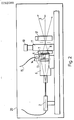
Wie Fig. 2 zeigt, wird das Lichtbündel eines Lasers 2 im Projektor 20 zunächst durch ein Objektiv 6 aufgeweitet. Dieses Lichtbündel beleuchtet dann zwei mit ihren Teilungen dicht benachbarte optische Strichgitter 7 und 8. Die Teilungen dieser beiden Ronchi-Gitter 7, 8 bestehen aus gleichbreiten geradlinigen Strichen und Lücken mit einer Periodenlänge von 50 um auf je einem Glasträger. Der Glasträger des Gitters 8 ist in einer um die optische Achse 3 drehbaren Fassung 9 montiert, welche durch ein von Hand am Knopf 10 zu betätigendes Mikrometergetriebe 11 um messbare Winkelbeträge gegenüber dem Gitter 7 drehbar ist.As shown in FIG. 2, the light beam from a
Das Gitter 7 ist über einen Befestigungswinkel 12 in einer Parallelführung 13 verschieblich. Die Verschiebung um messbare Beträge erfolgt über einen Schrittmotor 14, der über ein Kabel 15 von einer Steuer- und Auswerteelektronik 16 (Fig. 1) angetrieben wird. Die Glasträger der Gitter 7, 8 gleiten bei ihrer Relativbewegung gegeneinander und sind zweckmässig durch einen Oelfilm voneinander getrennt. Nach Durchlaufen der Gitter 7, 8 hat des Lichtbündel des Lasers 2 eine über dessen Querschnitt periodisch variierende Helligkeitsverteilung, wie weiter unten im einzelnen ausgeführt wird. Dieses Lichtbündel wird durch zwei Optiken 17, 18 auf einen dem Objekt 1 entsprechenden Querschnitt aufgeweitet.The grating 7 is displaceable in a
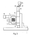
Die Anordnung der Strichgitter 7, 8 zeigt schematisch die Ansicht gem. Fig. 3, in der bereits zu Fig. 2 beschriebene Elemente die gleichen Bezugszeichen tragen, wie in Fig. 2. Zur Vereinfachung der Darstellung ist die Parallelführung 13 für das Gitter 7 in Richtung der optischen Achse 3 des Lasers 2 gesehen in Fig. 2 links vom Gitter 7 angeordnet, in Fig. 3 hingegen rechts. Die Teilstriche der Gitter 7, 8 können mit dem Mikrometergetriebe 11 waagrecht und zueinander parallel orientiert werden. Die aus dem Zusammenwirken der beiden Gitter 7, 8 entstehende Moiréfigur zeigt in diesem Fall in an sich bekannter Weise eine über den ganzen Lichtbündel-Querschnitt homogene Helligkeit, welche durch eine Höhenverschiebung des Gitters 7 in der Führung 13 veränderlich ist.The arrangement of the
Aendert man die Orientierung des Gitters am Mikrometergetriebe 11, so werden im Bündelquerschnitt senkrechte Moiréstreifen sichtbar, deren Streifenperiode mit zunehmendem Winkel zwischen den Gitterteilungsrichtungen immer kleiner wird und am Knopf 10 von Hand wählbar ist. Die Objektoberfläche 1 wird dann mit einem periodischen Streifenmuster beleuchtet, welches durch Höhenverschiebung des Gitters 7 nach rechts oder links verschieblich ist. Diese Höhenverschiebung erfolgt mittels des Schrittmotors 14 über zwei Ritzel 21, 22 und ein Mikrometergetriebe 23 an der Parallelführung 13. Dabei ändert sich für alle Objektpunkte die Beleuchtungsphase periodisch, es liegt eine Phasenmodulation vor. Sieht man auf dem einen Strichgitter, z.B. Gitter 7, eine Referenzmarke und eine bezüglich des Geräterahmens 24 fest einstellbare zugehörige Abtastvorrichtung vor, welche in Fig. 3 nicht mit dargestellt sind, so kann man ein Referenzsignal erzeugen, wenn bestimmte Objektpunkte bestimmte Beleuchtungsphasen durchlaufen.If you change the orientation of the grating on the
Die Auswertung der an der Objektoberfläche 1 deformierten Gitterbilder, die mit der Fernsehkamera 4 aufgenommen und in der Auswerteelektronik 16 gespeichert werden, geschieht in an sich bekannter Weise, vgl. die eingangs genannte Literaturstelle von C.L. Koliopoulos (1981) und wird hier nur kurz zusammengefasst. Diese Auswertung erfolgt gemäss einem vorbestimmten Zeitablauf, der durch die Aufnahmenorm der Fernsehkamera 4 gegeben ist. Der Schrittmotor 14 wird durch diesen Zeitablauf so gesteuert, dass in 800 ms durch 240 Motorschritte das Streifenbild auf dem Objekt 1 um 1/1 Moiréperiode verschoben wird. Die Fernsehkamera 4 umfasst einen CCD-Sensor mit 65'536 Einzelsensoren. Diese Einzelsensoren integrieren während der Bildverschiebung die einzelnen Bildpunktbeleuchtungen während je 33 1/3 ms und lesen dann je ein Gesamtbild in einen Speicher der Elektronik 16 aus. Während der genannten 800 ms werden also 24 Gesamtbilder ausgelesen. Dabei werden je 6 Bilder zu einer Bildsumme zusammengefasst, sodass sich 4 Bildsummen A, B, C, D ergeben. Diese Bildsummen werden nach einer Analog-Digital-Wandlung in zwei 65'536-fach Speicher M1, M2 wie folgt aufsummiert:
Bild 1 bis Bild 6 in 200 ms in M2 aufsummiert, ergeben Bildsumme A, danach
Bild 7 bis Bild 12 in 200 ms in M1 aufsummiert, ergeben Bildsumme (+B), danach
Bild 13 bis Bild 18 in 200 ms von M2 subtrahiert, erge ben Bildsumme A - C, danach
Bild 19 bis Bild 24 in 200 ms von M1 subtrahiert, ergeben Bildsumme B - D.The evaluation of the grid images deformed on the object surface 1, which are recorded with the television camera 4 and stored in the
Picture 1 to picture 6 summed up in 200 ms in M2, result in picture sum A, then
Picture 7 to picture 12 summed up in M1 in 200 ms, result in picture sum (+ B), afterwards
Figure 13 to Figure 18 subtracted from M2 in 200 ms, erge ben image sum A - C, then
Fig. 19 to Fig. 24 subtracted from M1 in 200 ms result in picture sum B - D.
Dividiert man für alle 65'536 Bildpunkte die Speicherwerte
Gegenüber bekannten Vorrichtung zur Vermessung von Objektoberflächen hat die hier beschriebene folgende Vorteile: Streifenbreite und Streifenphase können durch kleine und kontrollierte Gitterbewegungen genau und über einen grossen Bereich messbar verändert werden, und durch die Synchronisation des Schrittmotors mit dem Bildaufnahmezyklus erfolgen die Bildaufnahmen stets reproduzierbar genau an den vorgegebenen Streifenlagen des Moiréstreifenbildes.Compared to known devices for measuring object surfaces, the advantages described here have the following advantages: strip width and strip phase can be changed precisely and measurably over a large area by means of small and controlled grid movements, and by synchronizing the stepper motor with the image recording cycle, the images are always reproducibly accurate on the given strip positions of the moiré strip image.
Das beschriebene Ausführungsbeispiel erlaubt zahlreiche Varianten und Verwendungsformen. Durch gegengleiche Neigung der Strichgitter zueinander kann man bei Veränderung der Streifenbreite die Orientierung der Streifen auf dem Objekt konstant halten, und durch Anpassung der Streifenbreite an die Objekttiefe ist eine eindeutige Bestimmung der Höhen der Objektpunkte möglich.The exemplary embodiment described allows numerous variants and forms of use. By mutually equal inclination of the grids to one another, the orientation of the stripes on the object can be kept constant when the stripe width is changed, and by adjusting the stripe width to the object depth, the heights of the object points can be clearly determined.
Claims (5)
- Mitteln (20) zur Beleuchtung des Objektes mit einem Lichtbündel mit über dessen Querschnitt periodisch variierender Helligkeitsverteilung;
- Mitteln (16, 20) zur Modulation der Phase der Helligkeitsverteilung des Lichtbündels zur Beleuchtung;
- einer lichtelektrischen Detektoranordnung (4) zur Aufnahme von deformierten Gitterbildern des Objektes für eine Anzahl unterschiedlicher Modulationsphasen des Lichtbündels zur Beleuchtung und mit
- Mitteln (16) zur Verknüpfung der Helligkeitswerte an den, den jeweiligen Objektpunkten entsprechenden Einzeldetektoren der Detektoranordnung zur Berechnung der Höhe der Punkte der Objektoberfläche bezüglich einer Referenzebene, dadurch gekennzeichnet, dass
- die Mittel zur Beleuchtung und zur Modulation zwei Strichgitter (7, 8) umfassen, welche derart im Lichtbündel angeordnet sind, dass sich auf der Objektoberfläche (1) ein periodisches Streifenmuster ergibt und dass
- Mittel (13, 14, 21, 22, 23) zur messbaren linearen Verschiebung eines der Strichgitter (7) in seiner Ebene gegenüber dem anderen Strichgitter (8) vorgesehen sind derart, dass die Phase des Streifenmusters um messbare Beträge veränderbar ist.1. Device for measuring the surface (1) of an object with
- Means (20) for illuminating the object with a light beam with a brightness distribution which varies periodically over its cross section;
- Means (16, 20) for modulating the phase of the brightness distribution of the light beam for illumination;
- A photoelectric detector arrangement (4) for recording deformed grid images of the object for a number of different modulation phases of the light beam for illumination and with
- Means (16) for linking the brightness values at the individual detectors of the detector arrangement corresponding to the respective object points for calculating the height of the points of the object surface with respect to a reference plane, characterized in that
- The means for lighting and for modulation comprise two grids (7, 8) which are arranged in the light beam in such a way that results in a periodic stripe pattern on the object surface (1) and that
- Means (13, 14, 21, 22, 23) for the measurable linear displacement of one of the grids (7) in its plane with respect to the other grating (8) are provided such that the phase of the stripe pattern can be changed by measurable amounts.
- Mitteln (20) zur Beleuchtung des Objektes mit einem Lichtbündel mit über dessen Querschnitt periodisch variierender Helligkeitsverteilung;
- Mitteln (16, 20) zur Modulation der Phase der Helligkeitsverteilung des Lichtbündels zur Beleuchtung;
- einer lichtelektrischen Detektoranordnung (4) zur Aufnahme von deformierten Gitterbildern des Objektes für eine Anzahl unterschiedlicher Modulationsphasen des Lichtbündels zur Beleuchtung, und mit
- Mitteln (16) zur Verknüpfung der Helligkeitswerte an den, den jeweiligen Objektpunkten entsprechenden Einzeldetektoren der Detektoranordnung zur Berechnung der Höhe der Punkte der Objektoberfläche bezüglich einer Referenzebene, dadurch gekennzeichnet, dass
- die Mittel zur Beleuchtung und zur Modulation zwei Strichgitter (7, 8) umfassen, welche derart im Lichtbündel angeordnet sind, dass sich auf der Objektoberfläche (1) ein periodisches Streifenmuster ergibt und dass
- Mittel (9, 10, 11) zur messbaren Drehung eines der Strichgitter (8) in seiner Ebene gegenüber dem anderen Strichgitter (7) vorgesehen sind derart, dass die Länge der Periode des Streifenmusters auf vorbestimmte Werte einstellbar ist.4. Device for measuring the surface of an object with
- Means (20) for illuminating the object with a light beam with a brightness distribution which varies periodically over its cross section;
- Means (16, 20) for modulating the phase of the brightness distribution of the light beam for illumination;
- A photoelectric detector arrangement (4) for recording deformed grid images of the object for a number of different modulation phases of the light beam for illumination, and with
- Means (16) for linking the brightness values at the individual detectors of the detector arrangement corresponding to the respective object points for calculating the height of the points of the object surface with respect to a reference plane, characterized in that
- means of lighting and modulation comprise two line gratings (7, 8) which are arranged in the light beam in such a way that a periodic stripe pattern results on the object surface (1) and that
- Means (9, 10, 11) for measurably rotating one of the grids (8) in its plane with respect to the other grating (7) are provided such that the length of the period of the stripe pattern can be set to predetermined values.
Applications Claiming Priority (2)
| Application Number | Priority Date | Filing Date | Title |
|---|---|---|---|
| CH3804/86 | 1986-09-23 | ||
| CH380486 | 1986-09-23 |
Publications (2)
| Publication Number | Publication Date |
|---|---|
| EP0262089A2 true EP0262089A2 (en) | 1988-03-30 |
| EP0262089A3 EP0262089A3 (en) | 1989-08-09 |
Family
ID=4263804
Family Applications (1)
| Application Number | Title | Priority Date | Filing Date |
|---|---|---|---|
| EP87810519A Withdrawn EP0262089A3 (en) | 1986-09-23 | 1987-09-09 | Device for measurement of the surface of an object |
Country Status (1)
| Country | Link |
|---|---|
| EP (1) | EP0262089A3 (en) |
Cited By (16)
| Publication number | Priority date | Publication date | Assignee | Title |
|---|---|---|---|---|
| WO1990007691A1 (en) * | 1988-12-23 | 1990-07-12 | Klaus Pfister | Process and device for observing moire patterns on test surfaces by moireing with phase shifts |
| EP0379079A1 (en) * | 1989-01-17 | 1990-07-25 | Leica AG | - Apparatus for surveying the surface of an object by projection of fringe patterns |
| DE3843396C1 (en) * | 1988-12-23 | 1990-07-26 | Klaus 8206 Bruckmuehl De Pfister | Method and device for observing moiré patterns of surfaces under investigation in conjunction with the application of the projection moiré method with phase shifts |
| DE3934423C1 (en) * | 1989-10-14 | 1991-04-25 | Fraunhofer-Gesellschaft Zur Foerderung Der Angewandten Forschung Ev, 8000 Muenchen, De | Camera photographing topography of test piece surface - produces Moire image using CCD sensors recording phase shift between object grating and camera reference grating |
| DE4006343A1 (en) * | 1990-03-01 | 1991-09-05 | Bernd Dr Breuckmann | Evaluating strip patterns for optical measuring process - modulating by carrier frequency and imaging on sensor for evaluating by phase shift algorithm |
| US5135308A (en) * | 1990-03-09 | 1992-08-04 | Carl-Zeiss-Stiftung | Method and apparatus for non-contact measuring of object surfaces |
| US5135309A (en) * | 1990-03-09 | 1992-08-04 | Carl-Zeiss-Stiftung | Method and apparatus for non-contact measuring of object surfaces |
| DE4120115A1 (en) * | 1991-06-19 | 1992-12-24 | Volkswagen Ag | Contactless determn. of coordinates of points on surface - combining coded light application with phase-shift method using stripes of width corresp. to pattern period |
| US5185810A (en) * | 1990-04-26 | 1993-02-09 | Carl-Zeiss-Stiftung | Method for optical testing of samples |
| US5311599A (en) * | 1990-04-26 | 1994-05-10 | Carl-Zeiss-Stiftung | Method and apparatus for optical testing of samples |
| GB2277588A (en) * | 1993-04-21 | 1994-11-02 | Fraunhofer Ges Forschung | Surface topographic analysis |
| WO1998017971A1 (en) * | 1996-10-18 | 1998-04-30 | Innomess Gesellschaft Für Messtechnik Mbh | Method and device for measuring the course of reflective surfaces |
| DE19703741C2 (en) * | 1997-02-02 | 2002-02-28 | Henning Wolf | Optical measuring method for absolute three-dimensional measurement of the shape of objects |
| DE102004044695A1 (en) * | 2004-09-15 | 2006-03-30 | Sick Ag | Object distance measuring process, involves temporally illuminating object twice one after the other from different directions, and calculating distance of object on basis of received images from local misalignment of illuminating structure |
| WO2007137746A1 (en) * | 2006-05-30 | 2007-12-06 | Abramo Barbaresi | Device for acquiring a three-dimensional video constituted by 3-d frames which contain the shape and color of the acquired body |
| CN112361992A (en) * | 2020-11-10 | 2021-02-12 | 齐鲁工业大学 | Grating projection three-dimensional measurement method and device |
Citations (3)
| Publication number | Priority date | Publication date | Assignee | Title |
|---|---|---|---|---|
| US2886717A (en) * | 1953-03-14 | 1959-05-12 | Ferranti Ltd | Measuring apparatus |
| FR2493541A1 (en) * | 1980-11-04 | 1982-05-07 | Israel Atomic Energy Comm | METHOD AND EQUIPMENT FOR ANALYZING RADIATION DEVIATION |
| EP0182469A1 (en) * | 1984-09-14 | 1986-05-28 | New York Institute Of Technology | Apparatus and method for obtaining surface profilometry and three dimensional surface contours |
-
1987
- 1987-09-09 EP EP87810519A patent/EP0262089A3/en not_active Withdrawn
Patent Citations (3)
| Publication number | Priority date | Publication date | Assignee | Title |
|---|---|---|---|---|
| US2886717A (en) * | 1953-03-14 | 1959-05-12 | Ferranti Ltd | Measuring apparatus |
| FR2493541A1 (en) * | 1980-11-04 | 1982-05-07 | Israel Atomic Energy Comm | METHOD AND EQUIPMENT FOR ANALYZING RADIATION DEVIATION |
| EP0182469A1 (en) * | 1984-09-14 | 1986-05-28 | New York Institute Of Technology | Apparatus and method for obtaining surface profilometry and three dimensional surface contours |
Cited By (22)
| Publication number | Priority date | Publication date | Assignee | Title |
|---|---|---|---|---|
| US5202749A (en) * | 1988-12-23 | 1993-04-13 | Klaus Pfister | Process and device for observing moire patterns of surfaces to be tested by application of the moire method using phase shifting |
| DE3843396C1 (en) * | 1988-12-23 | 1990-07-26 | Klaus 8206 Bruckmuehl De Pfister | Method and device for observing moiré patterns of surfaces under investigation in conjunction with the application of the projection moiré method with phase shifts |
| DE3907430C1 (en) * | 1988-12-23 | 1991-03-21 | Klaus 8206 Bruckmuehl De Pfister | |
| WO1990007691A1 (en) * | 1988-12-23 | 1990-07-12 | Klaus Pfister | Process and device for observing moire patterns on test surfaces by moireing with phase shifts |
| EP0379079A1 (en) * | 1989-01-17 | 1990-07-25 | Leica AG | - Apparatus for surveying the surface of an object by projection of fringe patterns |
| DE3934423C1 (en) * | 1989-10-14 | 1991-04-25 | Fraunhofer-Gesellschaft Zur Foerderung Der Angewandten Forschung Ev, 8000 Muenchen, De | Camera photographing topography of test piece surface - produces Moire image using CCD sensors recording phase shift between object grating and camera reference grating |
| DE4006343A1 (en) * | 1990-03-01 | 1991-09-05 | Bernd Dr Breuckmann | Evaluating strip patterns for optical measuring process - modulating by carrier frequency and imaging on sensor for evaluating by phase shift algorithm |
| US5135309A (en) * | 1990-03-09 | 1992-08-04 | Carl-Zeiss-Stiftung | Method and apparatus for non-contact measuring of object surfaces |
| US5135308A (en) * | 1990-03-09 | 1992-08-04 | Carl-Zeiss-Stiftung | Method and apparatus for non-contact measuring of object surfaces |
| US5185810A (en) * | 1990-04-26 | 1993-02-09 | Carl-Zeiss-Stiftung | Method for optical testing of samples |
| US5311599A (en) * | 1990-04-26 | 1994-05-10 | Carl-Zeiss-Stiftung | Method and apparatus for optical testing of samples |
| DE4120115A1 (en) * | 1991-06-19 | 1992-12-24 | Volkswagen Ag | Contactless determn. of coordinates of points on surface - combining coded light application with phase-shift method using stripes of width corresp. to pattern period |
| GB2277588B (en) * | 1993-04-21 | 1997-05-28 | Fraunhofer Ges Forschung | Method of and device for topographic surface analysis |
| GB2277588A (en) * | 1993-04-21 | 1994-11-02 | Fraunhofer Ges Forschung | Surface topographic analysis |
| WO1998017971A1 (en) * | 1996-10-18 | 1998-04-30 | Innomess Gesellschaft Für Messtechnik Mbh | Method and device for measuring the course of reflective surfaces |
| US6392754B1 (en) | 1996-10-18 | 2002-05-21 | Innomess Gesellschaft Fur Messtechnik Mbh | Method and apparatus for measuring the profile of reflective surfaces |
| DE19703741C2 (en) * | 1997-02-02 | 2002-02-28 | Henning Wolf | Optical measuring method for absolute three-dimensional measurement of the shape of objects |
| DE102004044695A1 (en) * | 2004-09-15 | 2006-03-30 | Sick Ag | Object distance measuring process, involves temporally illuminating object twice one after the other from different directions, and calculating distance of object on basis of received images from local misalignment of illuminating structure |
| WO2007137746A1 (en) * | 2006-05-30 | 2007-12-06 | Abramo Barbaresi | Device for acquiring a three-dimensional video constituted by 3-d frames which contain the shape and color of the acquired body |
| US7929153B2 (en) | 2006-05-30 | 2011-04-19 | Abramo Barbaresi | Device for acquiring a three-dimensional video constituted by 3-D frames which contain the shape and color of the acquired body |
| CN112361992A (en) * | 2020-11-10 | 2021-02-12 | 齐鲁工业大学 | Grating projection three-dimensional measurement method and device |
| CN112361992B (en) * | 2020-11-10 | 2022-03-25 | 齐鲁工业大学 | Grating projection three-dimensional measurement method and device |
Also Published As
| Publication number | Publication date |
|---|---|
| EP0262089A3 (en) | 1989-08-09 |
Similar Documents
| Publication | Publication Date | Title |
|---|---|---|
| EP0379079B2 (en) | - Apparatus for surveying the surface of an object by projection of fringe patterns | |
| DE3829925C2 (en) | Device for the optical measurement of teeth in the oral cavity | |
| DE102008040949B4 (en) | Optical projection grating, measuring camera with optical projection grating and method for producing an optical projection grating | |
| EP3298344B1 (en) | Method and camera for the three-dimensional measurement of a dental object | |
| EP0262089A2 (en) | Device for measurement of the surface of an object | |
| EP0534284B1 (en) | Method and device for determining the absolute coordinates of an object | |
| EP3298346A1 (en) | Device for optical 3d measuring of an object | |
| DE102011077564B4 (en) | Method for the optical three-dimensional measurement of a dental object | |
| AT395914B (en) | PHOTOELECTRIC POSITION MEASURING DEVICE | |
| EP1715291B1 (en) | Projector for a system for three dimensional optical object measurement | |
| DE2156617B2 (en) | DEVICE FOR IMAGE CORRELATION | |
| DE4007502A1 (en) | METHOD AND DEVICE FOR CONTACTLESS MEASUREMENT OF OBJECT SURFACES | |
| DE3907430C1 (en) | ||
| WO2009063088A2 (en) | Method for optical measurement of objects using a triangulation method | |
| DE102016217628B4 (en) | A method of operating a surgical microscopy system, a motion sensing system for a surgical microscopy system, and an operating microscopy system | |
| DE102012206472B4 (en) | PROJECTION SYSTEM WITH STATIC PATTERN ELEMENTS AND MULTIPLE OPTICAL CHANNELS FOR OPTICAL 3D MEASUREMENT | |
| DE102013212409A1 (en) | Method for image acquisition of a preferably structured surface of an object and device for image acquisition | |
| DE4226683A1 (en) | Optical movement sensor using periodic pattern of slits - projects moving stripe pattern on to stationary masked photodetector giving electrical output proportional to distance moved | |
| DE19633686C2 (en) | Device and method for measuring distances and / or spatial coordinates of objects and / or their change over time | |
| DE4142676A1 (en) | Measurement of objects, esp. gear wheels, using projected stripe pattern, - involves evaluating periodically projected stripe patterns with projection-detection arrangements for front and rear tooth edges | |
| DE19749435A1 (en) | Optical measurement apparatus for three-dimensional measurement of object | |
| DE19846145A1 (en) | Three-dimensional imaging device for shape measurement has transmitter array whose elements move in straight, parallel lines | |
| DE10256725B3 (en) | Sensor for contactless optical measurement of relative velocity of material surface using detection of moving light pattern directed onto material surface via illumination device with controlled light sources | |
| DE4027328A1 (en) | Stereo camera for surface structure esp. of teeth - projects two beams from equal and opposite angles for illumination of surface monitored by image sensor | |
| DE19641168A1 (en) | Object surface measuring device |
Legal Events
| Date | Code | Title | Description |
|---|---|---|---|
| PUAI | Public reference made under article 153(3) epc to a published international application that has entered the european phase |
Free format text: ORIGINAL CODE: 0009012 |
|
| AK | Designated contracting states |
Kind code of ref document: A2 Designated state(s): DE FR GB IT SE |
|
| PUAL | Search report despatched |
Free format text: ORIGINAL CODE: 0009013 |
|
| AK | Designated contracting states |
Kind code of ref document: A3 Designated state(s): DE FR GB IT SE |
|
| STAA | Information on the status of an ep patent application or granted ep patent |
Free format text: STATUS: THE APPLICATION IS DEEMED TO BE WITHDRAWN |
|
| 18D | Application deemed to be withdrawn |
Effective date: 19900403 |
|
| RIN1 | Information on inventor provided before grant (corrected) |
Inventor name: ZUMBRUNN, ROLAND |